NEW: Learning electronics? Ask your questions on the new Electronics Questions & Answers site hosted by CircuitLab.
Support Forum » TRACTOR PULL SLED MONITOR
|
April 26, 2009 by JKITSON 
|
I NEED TO BUILD A SPEEDOMETER AND DISTANCE MEASURING MONITOR. I CAN PROVIDE A SIGNAL FROM A MAGNETIC SENSOR THAT SENDS A PULSE EVERY TIME A TOOTH ON A GEAR PASSES IT. NEED TO CALCULATE SPEED UP TO 5 MPH ie 2.8 MPH. NEED TO CALCULATE DISTANCE UP TO 250 FEET. HOW DO I CONVERT THE SIGNAL FOR THE AT168? THANKS JIM |
|---|---|
|
April 27, 2009 by mrobbins (NerdKits Staff) 
|
Hi Jim, Do you have more information about the magnetic sensor? Is it a "Hall effect sensor" with a digital output, or something else? If you have a digital output, you can just connect it to any free I/O pin. Otherwise, you'll have to do something more analog, possibly involving the ADC. Once you have the signal, you can try to count how many pulses arrive, and this will be directly proportional to distance. For your speed measurement, the simplest thing would probably be to count how many pulses arrive in a certain time window. You also might have to look into "debouncing" your input unless the analog part has sufficient hysteresis. That means that you don't want noise to make it look like many pulses are happening when really it's just in the middle of a transition. Let me know if that helps and if you have a model number or datasheet for the magnetic sensor. Mike |
|
April 27, 2009 by JKITSON
|
THANKS I WILL GET MORE INFO ON THE SENSOR.. JIM |
|
May 05, 2009 by JKITSON
|
Hi Mike, The sensor has no name or part #. It was purchased for a replacement pickup for a tach. in a motorhome. It is a 3/4 x 2 3/4" threaded houseing with a round magnet in the center. There are 2 leads coming out of the unit. When i connect one to ground (neg buss) and the other to the input a/d that the temp sensor used and flash metal bar past the sensor i get a numeric reading on the lcd of approx. .90 to 1.50. Hope this helps.. Jim |
|
May 05, 2009 by mrobbins (NerdKits Staff)
|
Hi Jim, I was able to find these two PDFs which describe this type of sensor: http://woodward.com/pdf/ic/82510.pdf and http://woodward.com/pdf/ic/02010.pdf. Does this look like your device? The way these sensors work is to have a permanent magnet embedded inside along with a coil of wire. The magnetic field lines from the magnet all have to make it from the north pole back to the south pole, but depending on whether a gear tooth is nearby, the field strength will change. A time-varying magnetic field is detected by the coil as a voltage. I think the first step to take is to mount the sensor and to run your motor at various speeds, and then to use a multimeter (in AC voltage mode) to measure the voltage and (if possible) frequency of the signal. The frequency will be the frequency at which the gear/flywheel teeth are passing by, and my guess is that the AC voltage will be proportional to this frequency. Measure at a few data points to be sure. Once you have an idea of how big the signal is, we'll be able to help you figure out whether any amplification is needed to get that kind of signal into the microcontroller. Mike |
|
May 06, 2009 by JKITSON
|
OK THANKS WILL DO JIM |
|
May 14, 2009 by JKITSON
|
HI MIKE I HAVE FOUND THIS OMROM E2E-X10E1 SENSOR. OMRON SPEC. SHEETS SEEM TO BE GOOD. IF THIS LOOKS GOOD TO YOU TO USE I WILL BUY 2 OF THEM (ONE FOR SPARE) THANKS JIM |
|
May 19, 2009 by mrobbins (NerdKits Staff)
|
Hi Jim, I haven't worked with that kind of sensor before, so I'm a bit hesitant to convey too much confidence, especially for a $70 part! The first thing I notice from the datasheet is that the supply voltage required is roughly 12-24V or 10-30V for the different models. That's a lot more than the 5V supply used for the kit, and it also means that sensor output voltage will be very high when there is no object present. Basically, I see a sensor that has three wires: one for ground, one for supply voltage (maybe +12V), and one open-collector output. You'll see this "open-collector" term frequently in sensors and sometimes in other digital components. It just means that in the "on" mode, the voltage at that node is pulled to ground (like a closed switch), and in the "off" mode, no current is drawn, so it's effectively a floating voltage. However, if you were to connect it directly to the microcontroller, a current would flow, because the open-collector output will try to stay around the sensor's supply voltage of +12V, and the microcontroller's input pin will cause a great deal of current to flow to prevent that voltage from rising above +5 volts. To deal with that, I think the easiest thing to do is to put in a resistor in series with the microcontroller input pin, such that the maximum current limits itself to some reasonable, non-harmful value. For example, with a 100K resistor, you'd have 12-5=7 volts across it, for a current of 70 microamps, which is small enough that you're not going to cause much heating or other damage. Mike |
|
June 06, 2009 by JKITSON
|
HI MIKE I THINK I HAVE MABY MADE IT TO 3rd GRADE IN "C" PROGRAMMING.... HAVE THE PROGRAM MOSTLY WORKING EXCEPT I CAN'T SEEM TO GET A FLOATING VARIABLE TO PRINT ON THE LCD, ONLY WHOLE NUMBERS. I DON'T SEE WHERE YOU ADDRESS NUMBERS WITH DECIMAL POINTS IN YOUR LCD LIBRARY.. I NEED TO DISPLAY xxx.xxx and x.xxx THANKS JIM |
|
June 06, 2009 by mcai8sh4 
|
Is this what your after : where decimal_number is a double. This will display x.xx use %.3f for x.xxx for xxx.xxx use the same (numbers before the decimal point are displayed anyway. If this is not what your after - post a little code snippet, so we can see what you're doing. |
|
June 06, 2009 by JKITSON
|
HI THANKS ALOT. WORKS PERFECT I SET IT FOR 3 AND JUST WHAT I WANT.. MY NEXT PART IS WRITING CODE TO COMPUTE MILES PER HOUR AND TRAP & HOLD MAX SPEED OBTAINED. HAVE THE RESET FEATURE WORKING AND THE HOLD INFO FEATURE WORKING. THANKS AGAIN FOR THE FAST REPLY JIM |
|
June 06, 2009 by mcai8sh4
|
Glad it worked! Once you have it calculating MPH, max speed shouldn't be a problem. I'd guess at a simple if statement, along the lines of The > is for '>' it wont let me enter that in the code on this forum - should read (speed > max_speed) I don't really know your setup so I can't help with the MPH calculations. I would imagine you'd have to something like know the distance moved per signal, then using the number of signals per second work out the MPH. You could use the example realtime clock tutorial to get the seconds, then the rest should be straight forward. Like I say, this may not work with your setup, just an idea. |
|
June 06, 2009 by JKITSON
|
HI AGAIN I WILL PUT THE REALTIME CLOCK PROGRAM IN AND GET IT WORKING.... I AM USING THE CALCULATION OF 1 TOOTH COUNT = .037 FEET. I WILL USE A VARIABLE FOR THE .037 SO IF IT CHANGES OR IS DIFFERENT JUST CHANGE THE VARIABLE... HAVE BEEN TRYING TO WORK OUT THE CODE ON PAPER FOR THE FORMULA OF: RATE=DISTANCE/TIME. RATE NEEDS TO BE IN MILES PER HOUR. DISTANCE IS CURRENTLY IN FEET. TIME WILL HAVE TO BE SCALED TO 1 HOUR I THINK TO MAKE THINGS WORK... ANY HELP WOULD BE APPRECIATED. JIM |
|
June 07, 2009 by mcai8sh4
|
I've just got out of bed (had a big night, so not quite sober yet, so expect errors), but it should be quite easy to calculate MPH with what you've told us. For starters, I would use Then you have a constant that can easily be altered (unless you want to alter this value with the program running). Then having the number of pulses (tooth count) and seconds (or 100th seconds) you can then work it out thus : 1 mile = 5280 feet and speed = dist / time so if you had 100 pulses over 1 second speed would be : To break this down to convert this into miles, divide by 5280 (number of feet in a mile) = 0.000700758 miles Perhaps define feet per mile as a constant as well. Then to get your hours, use To check you've got the maths right, it is quick and handy to use google calulator, as this can take care of the units for you. eg Go to google (www.google.com <- yeah, like I needed to give you the address) and in the search box type our example above, as in Click search and the first result should be your answer. So from this you can alter the equation you can alter the equation to suit your needs, then slap it all in a little function, conv_mph(), and you're laughing. |
|
June 07, 2009 by JKITSON
|
WOW FOR SOMEBODY WHO WAS OUT ALL NITE YOU ARE FANTASTIC,,,, I APPRECIATE THE INFO.. HAVE THE REALTIME CLOCK IN MY PGM AND WORKING... NOW TO TRAP HOW MANY COUNTS IN 1 SECOND... THEN THE REST IS SIMPLE MATH.. AFTER I GET THIS WORKING I WANT TO INTERFACE THIS TO A WIRELESS UNIT VIA THE SERIAL PORT. WILL NEED ANOTHER MICROCHIP FOR THE REC. END ALSO. YOUR SYSTEM IS GREAT... THANKS AGAIN FOR FANTASTIC SUPPORT. JIM |
|
June 07, 2009 by mcai8sh4
|
no problem. to be honest, I don't find maths too bad, but getting my head around this AVR thing... well, that's tricky. I'm amazed it worked, I had to spend a few hours in bed this afternoon to get rid of the hangover! Word of warning - Never do maths when drunk! To reiterate : Remember folk's, don't drink and derive! |
|
June 07, 2009 by wayward 
|
Nothing to add to mcai8sh4's excellent post; just a shortcut for Firefox users: the Search box to the right of the address bar can be used for quick Google calculations as well. You'll have to set the search engine to Google, if it isn't already, and then either click in the search box, hit Ctrl-K or Ctrl-L TAB to select it. Type/paste your formula et voilà, a dropdown box opens with the result — you don't even have to press Enter. Praise Google search suggestions! Sometimes you may have to add a final "=" at the end, if Google doesn't recognize your formula as such. |
|
June 07, 2009 by JKITSON
|
WELL HAVE DROVE MY SELF NUTS ALL DAY TRYING TO USE THE TIMER AND COUNT TEETH ON GEAR. GUESS I HAVE NOT MADE IT TO 4th GRADE YET... ANY HELP ON PROGRAM STRUCTURE TO GET THE COUNTS IN SAY 50/100 OF A SECOND WOULD BE NICE... THANKS JIM |
|
June 08, 2009 by mcai8sh4
|
Depending on how far you've got - I may be able to help, although we may be getting near my limits here. Have you got the chip to register a 'pulse' from the gear? Does it change the state of one of the pins? If so, there are several methods you can look at. 1) A simple if loop - so that if the pin is grounded you can increment a gear_count variable, then compare this number after say one second. 2) set up a pin change interrupt on the pin - when the pin alters state it then runs a function that increments the gear_count variable, then you can compare this. <- I think this is the better option, but more difficult to implement (for me at least). After you've compared the gear_count - reset the time to zero and start again. The realtime clock example counts up in 100ths of a second. So something along the lines of This simply checks until one second has passed, then sends the gear_count to the conversion function, which returns the speed given the gear_count per second (in the post above, gear_count would replace 100). Then reset the_time (so it starts counting the next second) and reset gear_count (so the count doesn't accumulate). Once you have speed then you can compare it with your desired speed and increase/decrease as required. There are many ways to achieve the above, and this is by no means elegant, but the theory's there. I hope this gives you some ideas as to how to continue. If it helps when I have a bit of free time, I'm going to have a play with the 'pin change interrupt', I'll post the code and a quick explanation, as I feel it could be useful for a number of things. (this may be next week though - I'm snowed under at work) Keep us all posted on how you get on. |
|
June 08, 2009 by JKITSON
|
THANKS WILL PLAY WITH THE IDEAS... I HAVE ALREADY PROGRAMMED A "LATCH" SO THAT I ONLY COUNT 1 COUNT PER TOOTH. I FOUND THAT THE MCU WAS SO FAST THAT IT COUNTED ABOUT 42 COUNTS PER TOOTH. MY LATCH IS WHEN THE INPUT PIN GOES LOW (0) I ADD 1 COUNT AND THEN SKIP COUNTING UNTIL THE PIN GOES HIGH (1). THEN DO IT OVER.. WORKS.. ONE NOTE WHEN I TRIED TO SET "the_time" VARIBLE TO 0 IT IGNORED ME AND CONTINUED TO COUNT ON UP. I HAVE "the_time" DISPLAYED ON THE LCD SCREEN. THANKS AGAIN FOR THE HELP AND IDEAS... JIM |
|
June 09, 2009 by mcai8sh4
|
Hmm, I'm just using and it resets it no problem (the time is declared globally as volatile int32_t the_time; Try making sure that your reset line in definatly being ran. If it's in a loop, check that the conditions are being met so the program enters the loop (if that makes sense) |
|
June 09, 2009 by JKITSON
|
OK WILL DO IF IT WILL RESET MAKES THIS EASIER... THANKS JIM |
|
June 12, 2009 by JKITSON
|
I WOULD LIKE TO USE SOME 3" 7 SEGMENT LED INDICATORS... HOW WOULD I INTERFACE 2 SETS OF NUMBERS X.X AND XXX.XX. I CAN GET A BUNCH OF MC74450P BCD DECODE DRIVER CHIPS!!!!! THANKS JIM |
|
June 16, 2009 by JKITSON
|
HI I NOW HAVE MY UNIT COMPUTING DISTANCE AS XXX.XX FEET AND MILES PER HOUR AS X.XX. I HAVE THE HOLD FEATURE WORKING AND THE RESET FEATURE WORKING... MY MAGNETIC INPUT IS YET TO BE INSTALLED ON THE SLED.... STILL NEED HELP WITH THE ABOVE POSTING.. WANT TO USE SOME BIG (3") SEVEN SEGMENT LCD DISPLAYS. I AM LOST AT THIS POINT AS TO HOW TO INTERFACE THEM. I JUST FINISHED PUTTING ALL THE COMPONENTS ON A PERM. PC BOARD AND CHECKS "OK" YOU "ALL" HAVE BEEN SUPER IN SUPPORT AND HELP. THANKS JIM |
|
June 18, 2009 by mcai8sh4
|
Jim - sorry it took a while, I've been away. If you're still having difficulty with the 7-seg displays, then maybe this link will help : 7 segment explained There's other bits on 7-seg diaplys on this site as well. To be honest, there's quite a few interesting bits on that site - worth spending 15 mins on. |
|
June 30, 2009 by JKITSON
|
HI THANKS FOR THE INFO ON 7 SEGMENT LCD'S. AT THIS POINT I AM PUTTING THEM ON HOLD. TO MUCH DESIGN AND TO LITTLE TIME... I WILL USE A SECOND NERDKIT FOR THE RECIEVE END. I NEED THE CODE TO SEND TWO VARIABLES ie XXX.XX AND XX.XXX TO THE SERIAL PORT. I WILL THEN INTERFACE THE SERIAL PORT TO A SMALL WIRELESS TRANSCEIVER AND THEN A SECOND TRANSCEIVER TO RECIEVE AND INTERFACE TO THE SECOND NERDKIT WITH LCD SCREEN. THANKS JIM |
|
July 27, 2009 by JKITSON
|
HI mcai8sh4 AFTER A MONTH OF TRYING I GOT THE SERIAL CODE FIGURED OUT... I AM HAVING A REAL PROBLEM MAKING A OUTPUT PORT OPERATE A RELAY. I HAVE SOME NEW 5VOLT COIL MINATURE RELAYS BUT CANT SEAM TO GET THE COMMANDS RIGHT TO TURN THEM ON OR OFF. int ready; DDRB |= (0<<PB1); // OUTPUT GREEN SLED READY STROBE if(ready) PORTB |= (1<<PB1); // TURN GREEN READY STROBE ON else PORTB |= -(1<<PB1); //TURN GREEN READY STROBE OFF THIS IS MY CODE FOR SETTING UP THE OUTPUT PORT PB1 AND THE LOGIC TO TURN THEM ON AND OFF. I HAVE ONE SIDE OF THE RELAY TO GROUND AND THE OTHER SIDE TO PORT PB1 ANY IDEAS THANKS JIM |
|
July 28, 2009 by Capt |
int ready; DDRB |= (1<<PB1); // OUTPUT GREEN SLED READY STROBE if(ready) { PORTB |= (1<<PB1); // TURN GREEN READY STROBE ON } else { PORTB |= -(1<<PB1); //TURN GREEN READY STROBE OFF } Pleas post some images of you work :) |
|
July 28, 2009 by mcai8sh4
|
To turn off PB1, I'd use : Capt : Jim's doing a similar idea to you to count revolution speed - well worth looking into how he's doing it!! Keep us posted Jim!! |
|
July 28, 2009 by Capt |
Damn, didn't read the his comment at PB1. You're right mcai8sh4 :) I know, that's why im at this thread ;) |
|
July 28, 2009 by JKITSON
|
HI BY PUTTING THE BRACKETS IN AS YOU SHOW AND USING HIS CODE THEY NOW WORK FINE. I WAS READING PAGES 73 & 74 IN THE ATMEGA168 MANUAL..WOW VERY CONFUSING.. HOW DO I GO ABOUT POSTING PICTURES OF MY ASSEMBLY ON THIS FORUM? DO YOU WANT ALL MY CODE? I AM AT ABOUT 242 LINES AT THIS POINT. THANKS FOR THE HELP.. JIM |
|
July 29, 2009 by Capt |
You could post your code at http://nerdkits.pastebin.com/ remember to click on forever under the "How long should your post be retained?" line. You probably need to use some images host. http://www.freeimagehosting.net/ http://www.imageshack.us/ What if every member here could have an images gallery? So that we could have like 3-4 images each of our nerdkits projects? |
|
July 31, 2009 by JKITSON
|
HI CAPT HAVE BEEN OUT OF TOWN FOR A FEW DAYS... IF YOU HAD A GALLERY OF SOME TYPE MY WIFE TAKES A LOT OF PHOTOS FOR A TRACTOR MAGAZINE WE PUBLISH SO WOULD BE EASY FOR US... THANKS FOR THE INFO. PS.....HAVE YOU TRIED THE ATMEGA328 YET?????? THANKS JIM |
|
August 11, 2009 by JKITSON
|
I NEED SOME HELP ON THE CODE TO READ FROM A SERIAL DEVICE AND INPUT INTO ATMEGA168 THEN DISPLAY ON SCREEN. I AM OUTPUTING FROM ONE ATMEGA168 VIA SERIAL TO A WIRELESS RADIO. THE OTHER WIRELESS RADIO IS CONNETCED TO A SECOND ATMEGA AND SCREEN. THIS IS MY CODE FOR OUTPUT: THIS IS WORKING TO THE SCREEN ON MY PC. THANKS JIM |
|
August 12, 2009 by mrobbins (NerdKits Staff)
|
Hi Jim, You should be able to use the scanf_P function to essentially reverse what you have sent. I would recommend that you change your sending code to include a newline: because this way it will be clear where one group of three starts and ends. And then, on the other MCU, you could use something like this to read the ASCII bytes from the serial link and turn them back into floating point variables: The ampersands before each variable mean that the compiler should give the scanf_P function the memory address of those variables instead of their contents, so that the scanf_P can fill those variables all at once. Please give this a try and let us know if it works! Sounds great to be communicating wirelessly between two kits. Mike |
|
August 12, 2009 by JKITSON
|
WOW THANKS I WILL TRY YOUR SUGGESTIONS AND LET YOU KNOW. JIM |
|
August 14, 2009 by JKITSON
|
TO MROBBINS I SET UP THE printF AND COULD NOT GET ANY DATA TO MY PC TERMINAL PGM. I FOUND THAT I HAD TO PRECEED EACH VAR. WITH (double) THEN THE DATA CAME THROUGH TO THE PC. NOW....PIN 2 ON MCU IS REC. AND 3 IS XMT. DO I CONNECT THE XMT ON MY RADIO TO REC ON MCU? I DID BOTH ENDS WITH A CROSSOVER CONNECTION. NO DATA FLOW..... ANY IDEAS? THANKS JIM |
|
August 14, 2009 by JKITSON
|
HI ME AGAIN MY BRAIN JUST WOKE UP.... THE RADIOS ARE 19200 BAUD AND I STILL HAVE NERDKITS AT 115000. WILL TRY MY HAND AT SETTING UP NERDKITS TO 19200 AND LEAVE THEM THERE. MY PROGRAMMING WILL BE A BIT SLOWER BUT THAT IS OK... JIM |
|
August 15, 2009 by JKITSON
|
HEY YOU ALL THE TWO NERDKITS ARE COMMUNICATING..... I FOUND ALL I HAD TO DO WAS ADD THE FOLLOWING LINE AFTER THE uart_init(); LINE UBRR0L = 47; //NOTE 47 IS FOR 19200 AND THE "0" IN UBRR0L IS A "ZERO" NOT AN "OH" THIS ONLY CHANGES THE BAUDRATE TO 19200 WHEN MY PROGRAM RUNS BUT DOES NOT CHANGE THE 115200 FOR PROGRAMMING... WHEN I CHANGE ANY DATA ON THE MASTER THE REMOTE FOLLOWS WITH ALMOST NO DELAY. I DID HAVE TO USE A CROSS CABLE ie XMT TO REC AND REC TO XMT. NOW I HAVE TO FINISH MOUNTING IN ENCLOSURES AND PUT ON THE SLED. JIM |
|
August 19, 2009 by JKITSON
|
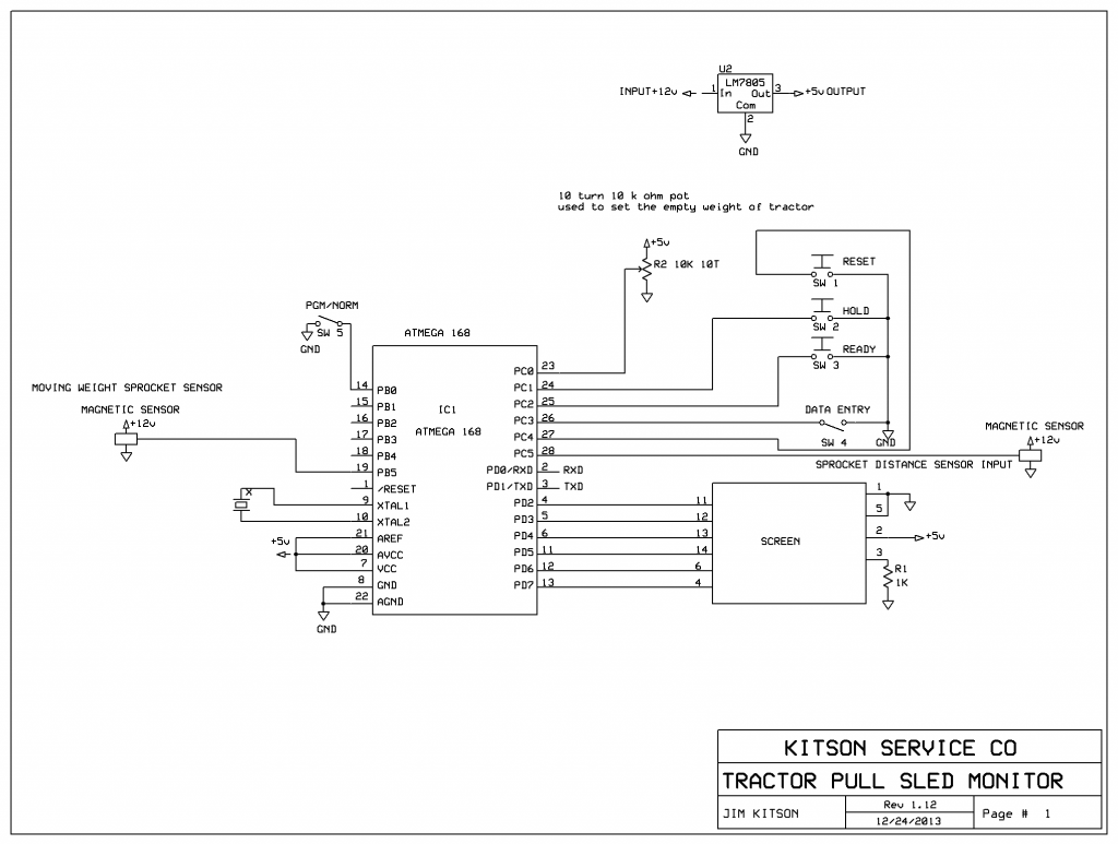
THIS IS THE COMPLETED MASTER UNIT FOR THE SLED
|
|
August 19, 2009 by JKITSON
|
LETS TRY THIS LINK LINK TO IMAGE |
|
August 19, 2009 by JKITSON
|
LETS TRY THIS LINK AGAIN
|
|
September 06, 2009 by JKITSON
|
HERE IS THE INSIDE WIRING OF THE MASTER UNIT JIM |
|
September 06, 2009 by mcai8sh4
|
Jim, Thats looking great!! The whole thing is impressive, but the icing on the cake has to be the wireless part. Great work. What kind of range can you get with the wireless? |
|
September 06, 2009 by JKITSON
|
I AM GOING TO MOUNT THE UNITS ON THE SLED TOMORROW AND DO THE FINAL TESTS AND FINAL CALIBRATION BY PULLING THE SLED 200 MEASURED FEET AND ADJUST MY CONSTANT IN THE PROGRAM TO MATCH A READOUT OF 200 FEET. SO FAR IN TESTING I HAVE BEEN 400 FEET APART AND STILL WORKS. I WILL COMPILE A LIST OF THE ACTUAL PARTS ie RADIOS AND WHERE I PURCHASED THEM. JIM |
|
September 06, 2009 by rajabalu21 
|
Jim, The pictures look great. All the best for the field test. -Raja |
|
September 13, 2009 by jsukardi |
Jim, do you have a chance to compile list of the parts? For the wireless part, do you just pull it off a PC USB (USB is basically an advanced version serial port) wireless adapter? How do you configure the Authentication for the wireless? Johannes |
|
September 13, 2009 by JKITSON
|
THE TRANSCEIVERS I USED ARE IN THE 433 MHZ FSK. THEY USE RS-232 SERIAL INPUT & OUTPUT. THESE ARE OPEN UNITS WITH NO AUTHENTICATION. THEY USE 3.3 TO 4 VOLTS POWER. THE SERIAL OUT PUT FROM THE 168 CHIP (PINS 2&3) GO DIRECT THE THE RS-232 INPUT & OUTPUT ON THE RADIOS. THEY WORK AT 19200 BAUD SO YOU HAVE TO SET YOUR PROGRAM TO USE 19200 TO COMMUNICATE. SO FAR THEY WORK GREAT I BOUGHT THEM FROM http://www.sure-electronics.com/ PART #GP-GC010 UNDER 18.00 FOR THE PAIR. HOPE THIS HELPS JIM |
|
September 18, 2009 by IvonV |
So, Jim when you program, do you remove the wireless from the header and replace it with the programming unit or did you figure a way to daisy chain the programming header with the wireless and address each component serially? |
|
September 18, 2009 by JKITSON
|
I PURCHASED EXTRA 4 PIN HEADERS AND CABLES FROM NERDKITS. THIS WAY I PLUG THE SERIAL INTO THE USB FOR PROGRAM DOWN LOADS THEN INTO THE RADIO LINK FOR NORMAL OPERATION... THIS WAS THE SIMPLE WAY FOR ME TO DO IT... HOPE THIS HELPS JIM |
|
September 20, 2009 by IvonV |
Yes, thanks for the response Jim. Has anyone tried connecting multiple serial devices to the MCU (maybe even including the programming header)? That's a discussion or project or tutorial I'd like to see. |
|
September 28, 2009 by dangraham |
Hi Jim, I am trying to get my first project off the ground, well running anyway:) What system have you used to measure the output of your sensor and give you speed? I am using a latching type hall sensor with north/south magnets. I am thinking of using ICP1 and timing either the on or off periods. Any help would be great, thanks. |
|
October 09, 2009 by JKITSON
|
FOR DANGRAHM SORRY FOR THE DELAY.. HERE IS MY CODE FOR MAKING A "LATCH" TO ONLY GET 1 COUNT PER TOOTH ON MAGNETIC SENSOR. ALSO THE CODE FOR COMPUTING SPEED IN MILES PER HOUR. YOU WILL NEED TO INCLUDE IN THE BEGINNIG OF YOUR PROGRAM THE "REAL TIME CLOCK" LIBRARY AND ROUTINE. if(latch) goto latch_test; //latch ckt is to allow only 1 count per tooth //from the magnetic sensor on drive line. if(b3) count = count; //if input is high leave count same else {count++; gear_count++; //if input is low add "1" to count latch = 1;} latch_test: if (mph_time >= 100) //RUN LOOP FOR 1 SECOND (100 CYCLES) AND COUNT THE THEETH { // FROM THIS WE COMPUTE MILES PER HOUR speed = ((gear_count * tooth_distance) / 5280) / .0002777; //.0002777 = 1/3600 (3600 SECONDS IN AN HOUR) mph_time = 0; gear_count = 0; } if(speed > max_speed) max_speed = speed; //UPDATE max_speed IF speed IS GREATER if(b3) latch = 0; travel = count * tooth_distance; //increment by distance traveled for each tooth count HOPE THIS IS SOME HELP JIM |
|
November 23, 2009 by JKITSON
|
I AM BUILDING A NEW REMOTE READOUT. I NEED ONE MORE OUT PUT PIN ON THE ATMEGA 168. HOW CAN I CHANGE PIN1 FROM "RESET" TO BE A NORMAL OUTPUT PIN? I THINK I SAW WHERE IT IS DEFINED IN ONE OF THE LIB'S THAT WE CALL IN THE BEGINNING BUT HAVE NOT BEEN ABLE TO SPOT IT AGAIN.. THANKS JIM |
|
November 24, 2009 by pbfy0 |
I think to use PC6 as an i/o you need some kind of programmer to program the fuses. To use PC6 as i/o, you set the RSTDISBL fuse (the fuses would end up being lfuse: 0xF7 hfuse: 0x55 efuse: 0x01). I wrote a library (untested) to use a 7-segment display. here and here, that might work. |
|
November 24, 2009 by JKITSON
|
HERE IS A PARTIAL SCHEMATIC OF THE 8 DIGIT DISPLAY I NEED. YOU CAN SEE THAT I NEED TO CHANGE PIN 1 (RESET) TO AN OUTPUT PIN TO CONTROL THE LAST DIGIT.
|
|
November 26, 2009 by pbfy0 |
for the first source this would work better (it uses a string in PGM instead of in RAM). |
|
November 29, 2009 by JKITSON
|
TO pbfy0 YOUR CODE LOOKS GREAT... I SEE HOW YOU CONTROL EACH SEGMENT etc. WHAT I DON'T SEEM TO BE ABLE TO SEE IS HOW I CAN "MULTIPLEX" THIS TO CONTROL 8 SEVEN SEGMENT DISPLAYS FROM 1 MCU.... MORE INFO WOULD BE APPRECIATED THANKS JIM |
|
November 30, 2009 by pbfy0 |
Sorry, I didn't think you needed so many, and you can't multiplex. |
|
November 30, 2009 by mrobbins (NerdKits Staff)
|
Hey Jim, Instead of having one pin of the microcontroller for each /EL (or on your diagram LE/STROBE) line, how about adding a chip like the 74HC164, which is a serial-in, 8-bit-out shift register. You could control it with just 2 pins from the microcontroller (one data and one clock), and then you would have each one of the outputs connected to a LE/STROBE of each 7-segment decoder. You basically want to have all of the /EL lines be high except for one at any given time, so you could shift a single zero around as needed. This might also let you use something more like pbfy0's approach without the '4511 BCD-to-7seg decoder chips. Just a thought... Mike |
|
November 30, 2009 by JKITSON
|
MIKE THANKS FOR THE DIFFERENT VIEW. I THINK I WILL TRY THIS ROUTE.. ALSO---- MANY THANKS TO YOU FOR YOUR SUGGESTIONS ON "EXPRESSCH AND PCB" PROGRAMS. THEY ARE FANTASTIC... I GOT MY FOUR PC BOARDS LAST WEEK AND THEY WERE PERFECT.. I WILL REDRAW MY SCHEMATIC USING THE 74HC164 AND POST FOR YOUR REVIEW. THEN WILL START THE PROGRAMMING. I THINK I WILL HAVE TO RETAIN THE 4511 REGISTERS AS THEY RETAIN THE LAST VALUE AND KEEP IT DISPLAYED UNTIL THE NEXT DATA UPDATE. YOUR KITS AND FORUM ARE THE BEST I HAVE FOUND AND USED. THANKS AGAIN FOR THE HELP JIM |
|
November 30, 2009 by JKITSON
|
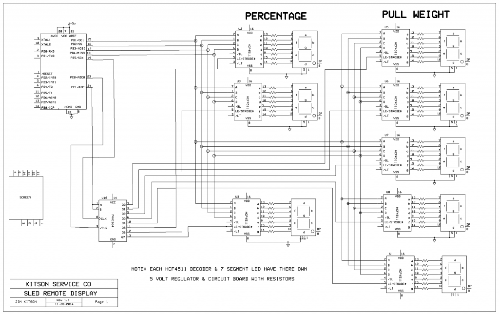
TO MIKE HERE IS AN UPDATED SCHEMATIC. I THINK THIS IS WHAT YOU WERE THINKING ABOUT.
JIM |
|
November 30, 2009 by JKITSON
|
WILL TRY TO GET A GOOD IMAGE THIS TIME---- !(http://s192.photobucket.com/albums/z235/justjudy_photos/?action=view¤t=SLEDREMOTEDISPLAY-1.jpg) JIM |
|
December 01, 2009 by pbfy0 |
the image format should be like this: and the alt is necessary. so here's the image:
|
|
December 01, 2009 by JKITSON
|
THANKS ALOT I LET MY MIND READ THE [alt name] AS BEING AN ALTERNATE OPTION.. NEXT TIME I WILL TRY TO GET IT RIGHT. THE "EXPRESSCH" PROGRAM FOR DRAWING SCHEMATICS IS VERY GOOD. TOOK A WHILE TO LEARN HOW TO USE IT. THANKS AGAIN TO ALL OF YOU FOR SUPER HELP.... JIM |
|
December 03, 2009 by JKITSON
|
HI AGAIN AS YOU CAN SEE FROM MY SCHEMATIC I HAVE THE HARDWARE PRETTY WELL ORGANIZED... NOW TO PROGRAMMING.. I HAVE TWO VARIBLES WITH DATA, "TRAVEL" FOR DISTANCE TRAVELED WHICH IS A INITALIZED AS A DOUBLE. IT CAN HAVE A VALUE LIKE 159.48. I NEED TO BREAK "TRAVEL" DOWN TO 5 INDIVIDUAL INTEGERS EACH ONE WITH THE FIRST DIGIT, SECOND,,,,,, . HOW DO I PARSE THE "DOUBLE VARIABLES" 1 DIGIT AT A TIME AND SAVE TO AN INTEGER? HAVE BEEN READING MY SECOND EDITION BOOK BUT IF IT IS THERE I DONT KNOW WHAT TO LOOK FOR.. THANKS JIM |
|
December 04, 2009 by pbfy0 |
maybe |
|
December 04, 2009 by JKITSON
|
PBFY0 THANKS I WILL GO TO THE BOOKS AND STUDY, THEN TRY SOME CODE.... THANKS AGAIN JIM |
|
December 05, 2009 by JKITSON
|
PBFY0 YOUR SUGGESTIONS SURE HELP. AFTER MANY HOURS IN THE BOOK AND TRYING CODE I CAME UP WITH THIS MUCH PGM.I AM USING ICC-WIN32 TO DEVELOP AND TEST PROGRAMS ON SCREEN BEFORE TRANSFERING TO WINAVR AND THE ATMEGA 168. HERE IS THE CODE THAT TAKES A 5 DIGIT 2 PLACE DECIMAL NUMBER AND BREAKES IT DOWN INTO 5 INDIVIDUAL SINGLE DIGIT VARIABLES. NEXT PART IS CONVERTING EACH SINGLE DIGIT VARIABLE TO 4 BIT BINARY.... include <stdheaders.h>int main() { int d1, d2, d3, d4, d5; //variables to hold the individual values of the variable travel int d6, d7, d8; //variables to hold the individual values of the variable speed int i; double travel, speed; char str[6]; //define str variable to be a max of 6 characters travel = 193.56; //set the value of travel for testing, in use the max will be less than 250.99 speed = 2.98; //set the value of speed for testing, in use the max will be less than 9.99 |
|
December 06, 2009 by pbfy0 |
here's a better formatted version, also with some edits: |
|
December 06, 2009 by pbfy0 |
should be: if you want actual digits. %2u will do 2 digits, so since the numbers only will only be one digit, you should use %1u |
|
December 31, 2009 by JKITSON
|
Here is the code i finally came up with.... turned out to be very simple to pad the leading blank spaces in a variable with zero's... Now to programming the conversion of binary 4 bit word to individual variables and set the outputs to 1 or 0.... define F_CPU 14745600include <stdio.h>include <math.h>include <stdlib.h>include <avr/io.h>include <avr/interrupt.h>include <avr/pgmspace.h>include <inttypes.h>include "../libnerdkits/delay.h"include "../libnerdkits/lcd.h"include "../libnerdkits/uart.h"int main() { // start up the LCD lcd_init(); FILE lcd_stream = FDEV_SETUP_STREAM(lcd_putchar, 0, _FDEV_SETUP_WRITE); lcd_home(); while (1)
{ } return (0); } |
|
December 21, 2011 by JKITSON
|
The time has come to improve my design. I think i need to implement interrupts on my signal input. I have changed 3 times on sensors and now am using a infrared sensor on the sprocket. I am having a hard time getting my mind around interrupts. I think I need to trigger on slope change, either way is ok. I only need a pulse to indicate change Any comments would be appreciated. Thanks NERDKITS for your system and the time invested in all of us... Jim Kitson |
|
January 16, 2012 by JKITSON
|
Hi.. I got the (PCI) interrupt to finally work. Well kind of!! I see where there are two interrupts that you can trigger on hi, low, rise, or fall. These ports are used by the lcd display. Is there any way a pin_change_interrupt be made to trigger on rise or fall of signal? Thanks Jim |
|
January 31, 2012 by JKITSON
|
I need to have pin's 4 & 5 on mcu for interrupts. They are now used by the LCD screen. What do I have to change to move the screen wires to some other pins on the mcu? I have looked at the lcd.c but not sure where to change. Any help appreciated. Thanks Jim. |
|
January 31, 2012 by mongo 
|
Hey Jim, It has been a while since I had time to mess with mine but I never did get the 433 MHz txrx to talk. I just re-read the thread and I caught something I missed a while back... That little board between the NK and the transceiver is an RS232 converter, isn't it? That may be what has been throwing me all this time. |
|
January 31, 2012 by JKITSON
|
MONGO That board is a 3.3volt power supply. The first radios I purchased were 3.3v only. I now have a pair that are 5v. Use a cross over connection. tx to rx. Mine works to about 1000 feet. Have one problem of data shifting 1 character on rec. I shifted my software in the rx unit and all works...Jim |
|
February 01, 2012 by Rick_S 
|
You could go I2C with the LCD that only uses two lines of your micro-controller (SDA & SCL). Here is a link to that thread. The library I created is a few posts in. This is a great way to cut down the number of connections required by the LCD. Rick |
|
February 01, 2012 by JKITSON
|
Rick I don't think there is enough program space left to add SPI along with my existing SLED program. SPI would be a good idea otherwise. Thanks for the info. I read the posts and will have to read them many more times to get a better grasp of SPI. Thanks Jim |
|
February 01, 2012 by Ralphxyz 
|
That's I2C Rick is referring to not SPI. His I2C library works great even for someone with limited capacities like myself. If you are running out of program space there are a couple of Master/Slave multi processor threads here published in the past year. One also uses I2C. And another uses SPI Both of these were contributed by Noter (who we miss). Using one of these methods you can have a intelligent port expander. I think you can use 20 pins on a slave for I/O and also do parallel processing. Ralph |
|
February 01, 2012 by JKITSON
|
Ralph I got a little off track on my last post. Thanks for correcting me. What I really need is int0 and int1 ports (pins 4 & 5) so I can trigger an interrupt on the rise of a trigger (tooth on sprocket). Using regular pin change interrupts I get two interrupts for each tooth. This slows my program operation two much. I am using pcint13 (pin 28) at this time and program works but two slow. Thanks Jim |
|
February 01, 2012 by mongo
|
Jim, The units I have are CyR2196R Is that the same? I have been able to get data to them but nothing comes out the receiving end. Do they take TTL or RS232 signal? I have been trying TTL in both polarities to no avail. The paperwork that came with them says 5V. |
|
February 01, 2012 by JKITSON
|
Mongo, THE SERIAL OUT PUT FROM THE 168 CHIP (PINS 2&3) GO DIRECT THE THE RS-232 INPUT & OUTPUT ON THE RADIOS. MINE WORK AT 19200 BAUD SO YOU HAVE TO SET YOUR PROGRAM TO USE 19200 TO COMMUNICATE. I cut & pasted this from a previous post. Mine were RS-232. Had to use cross over wiring ie tx to rx. Make sure you change the baud rate in your program to match the radio's baud rate. The line of code for mine was UBRR0L = 47; Jim |
|
February 02, 2012 by mongo
|
So far, I have only been generating data through the USB port and into the transmitter. I set the USB port to 19200 and can watch the signals go into the transmitter but there does not appear to be anything at the receiver end. Translating the TTL signal from the USB adapter, (USB/TTL) is done with a transistor so that a high on the TTL line is inverted to a low at the transmitter. and VS/VSA. I can see the signals on the scope at one end but nothing at the other. Maybe I should be using RS232 levels instead of TTL levels? |
|
February 02, 2012 by JKITSON
|
I use the RS232 xmt/rec from pins 2&3 on the 168 to the radio. I use a second radio and a second 168 to rec the data & display on screen. HUMBERTO: I have been looking at the lcd.c & am having problems figuring out where to make the changes to free pins 4 & 5, then change to some other pins. Any ideas..... Thanks Jim |
|
July 09, 2013 by JKITSON
|
UPDATE... I finally was able to get the Sled Monitor to work. Used it for our July 4th tractor pull. Have spent the last year learning how to use interrupts. I wrongly assumed my problems were hardware.. Not so just dumb programming.. I am calculating the distance pulled and the actual weight applied to the sled plate. Am using two sprockets & IR sensors. One sprocket on the differential drive line and the other on the shaft that moves the weight dolly on the sled. After I clean up the program I will post with photos of the setup. Thanks to all of you who have posted about interrupts. With out them & the Nerdkits site I don't think I could have made it happen.. Jim |
|
July 10, 2013 by JKITSON
|
This is the current working program. There are some variables & program lines for future use. The biggest problem I had was the proper placement of the interrupt parts. |
|
September 30, 2013 by JKITSON
|
I have finally got the SLED MONITOR to work properly & dependable. I had to replace the IR sensors at the sprockets with magnetic sensors. I found the Arizona sand and dust coated the lenses enough to cause errors. Now I can go forward on the Wireless and large led display features... Jim |
|
October 01, 2013 by Rick_S
|
Cool, Jim Keep us posted. Take pictures once you get your displays made. Rick |
|
October 01, 2013 by sask55 |
Jim Your project looks interesting. A few years back tractor pulls were much more common around here in central Saskatchewan Canada. Now I only see the one event, for vintage tractors only, which is held annually at a very large agricultural trade show. I am just curious, If you don’t mind saying, roughly where are you using your sled? Are tractor pulls common there now? What size (weight) of tractor can your sled accommodate? |
|
October 01, 2013 by JKITSON
|
I am in Page, Arizona. We have two official pulls a year, July 4th and the first weekend in October. My wife & I go to 6 to 8 other tractor pulls in a 5 state area around AZ. Our pulls are Antique tractors over 30 years old and under 100 hp and under 10,000 lbs. The sled I built will go to 14,000 lbs on the skid plate. Go to http://pagetractorpull.blogspot.com/ for more information. Thanks for your interest...Jim |
|
October 01, 2013 by mongo
|
Hey Jim, Just wondering... Could you put the schematic for the transceivers and connections to the NK in here? I have not had time to mess with mine lately and need a refresher in it... Man it's tough being self-employed. Thanx |
|
October 02, 2013 by JKITSON
|
Mongo Am getting ready for our annual tractor show this weekend (Oct 5&6). Will post next monday or tue. Tough being retired also. Have more to do & takes much longer to get done....Jim |
|
October 21, 2013 by JKITSON
|
Magnetic pickup info: I have tried six different sensors on the Sled. Most of them kind of work. I finally found the RED LION brand of LOGIC MAGNETIC PICKUPS. The LMPC0000 really works fine. I have been able to purchase them on Ebay for $15 to $25. Kind of pricy but very stable and easy to setup. Mongo: I seem to have lost the schematics in my last computer swap. I will draw up some new ones & post for you. Jim |
|
October 21, 2013 by esoderberg 
|
Jim, I'm with you, those commercial magnetic sensors are nearly bullet proof. I tried making my own custom mag pickup circuits, but it ended up being just as expensive and, while my home made versions worked, weren't nearly as robust. I'll add the link for the version I'm now using; looks comparable to the Red Lion, but the supply voltage can go down to 5v, which might be useful for Nerdkit projects, plus it seems to be cheaper new than I could find the Red Lion. |
|
October 22, 2013 by BobaMosfet 
|
esoderberg- Why was it just as expensive? I ask, because I looked at the datasheet, and it looks like < $5 in parts necessary to do it. Final unit could be sealed in acrylic resin if done carefully to seal it from the outside elements. My reference is the $23-$25/per price-tag I see on digikey. If it was much lower when you got yours that explains my confusion. BM |
|
October 22, 2013 by esoderberg
|
BM It wasn't so much the cost of individual components; I was mounting them on a PCB. If I were to produce a dozen or more the cost per unit would be in the range you figured, but I spent about $20-25 upfront to make the first one. Plus my design would have needed more upgrading too to be really comparable - it was set to detect a magnetic pole, not just a ferris object. But your point is valid, if you were to just put the components together on perf board and seal them up with resin you'd be able to come in at a noticeably smaller cost. Eric |
|
October 22, 2013 by BobaMosfet
|
esoderberg- That explains it-- thank you. BM |
|
October 22, 2013 by BobaMosfet
|
jkitson- In your code, since it appears that count is already itself, is there a reason you wrote your code this way: as opposed to: Just curious. BM |
|
October 22, 2013 by JKITSON
|
BM Thanks.. You are right. I forget about using the "not" logic. I will change my program the next time I do some changes. Jim |
|
October 23, 2013 by BobaMosfet
|
jkitson- Wasn't a criticism, FYI. Just wondered if I understood your logic. :P BM |
|
October 28, 2013 by mongo
|
Jim, I know the feeling about things taking longer... I sat on my project for several months for the lack of time but now that the winter is coming, I will have a little more indoor time myself. Been trying to get those transceivers to at least talk in one direction but still no luck. |
|
October 28, 2013 by BobaMosfet
|
mongo- I looked up your part # 'CyR2196R', but didn't find anything, can you provide more info, please. I'd like to look at them. Perhaps I can help. BM |
|
October 28, 2013 by JKITSON
|
MONGO..
I used RS232 signals. Use a crossover, xmt on atmega to rx on radio and rx on atmega to
xmt on radio. I programed a second atmega to use on the second radio. I wired it with the same crossover. Use the UBRR0L=47 to set the baud rate to 19200. I use the following code on the xmtr side printf_P(PSTR("%.0f %.0fn"), travel, weight);. I can not find the code for the second radio. Will get it for you tomorrow. Jim |
|
November 06, 2013 by JKITSON
|
Another need for the Tractor Sled Monitor!!!! I would like to be able to input the static weight of the tractor into the mcu. Then I can compute the Distance pulled, the Weight on the sled, & the Percentage pulled. I need to add a 10 key number pad and be able to input 4 numbers (1000 to 9999 pounds). I may need to upgrade to a 328 chip for more memory. Any ideas would be appreciated.. Thanks Jim |
|
November 06, 2013 by esoderberg
|
Jim, To minimize any additional hardware requirements, you could use a menu with a single button to input weight; have weight displayed on LCD and increment with button pushes from 1000 to 9999 and round robin at the top; use a fast increment feature with steady button hold to make input less tedious. Eric |
|
November 06, 2013 by JKITSON
|
Eric. I had not thought of this approach. Will look into it. Possibly could set the 1st digit then roll to the 2nd etc. Sure would be simpler than a 10key pad... Thanks again, this forum sure works. Jim |
|
November 06, 2013 by Rick_S
|
My real time clock project had a feature like that for setting the time. You can find the code HERE. It should be easy enough to modify for your needs. May not be the most optimized method or even the best way to go but it works for me :D Rick |
|
November 06, 2013 by JKITSON
|
Thanks Rick.. The use of the CASE structure sure will help in mine.. Jim |
|
November 07, 2013 by esoderberg
|
Another idea with simple HW: display weight on LCD and then use the ADC to read voltage across a trimpot for adjustments. SW would be just a small mod to NK temp sensor code. |
|
November 07, 2013 by Noter 
|
Now that's a cool idea! Much simpler than coding for a single button. |
|
November 07, 2013 by JKITSON
|
WOW This is neat. Thanks Noter for this concept. I think this is the easiest so far. You all are what makes the Nerdkits site so good. Thanks again. I will get started and keep you posted. Jim |
|
November 22, 2013 by JKITSON
|
esoderburg: I need to order a 10 turn pot. What value would you suggest. I want to scale the pot to read 1000 at one end and 10000 at the other. I don't have any to experiment with so hate to purcase an assortment. Any info appreciated. Thanks Jim |
|
November 22, 2013 by esoderberg
|
A relatively standard 10kohm linear pot should work well for your application. The output range for a pot like this should be close to 0-Vcc; scaling for 1k to 10k on the output should be relatively easy and look something like this: output reading = 1000 + 9000*(adc_reading/adc_reading_max). |
|
November 22, 2013 by JKITSON
|
Thanks I almost ordered a 10k. Then thought this is to simple. Our tractors all weigh over 1000# and cannot be over 10000#. (Insurance Company limits). Most are in the 3500# to 6500# range so most of the time the pot will only be a few turns up or down to find the weight. I will have a switch that will run a while loop to set the weight. After weight is set exit loop and back to normal program and not having to use adc till next tractor. Jim |
|
December 16, 2013 by JKITSON
|
esoderburg: Have set up a breadboard with 10k 10 turn pot. Used the temp pgm to start. The concept worked perfect. So simple and very stable. I left the 100 sample & averge parts in. I use a while loop that activates by a switch. Dial in the desired weight then turn switch off & back to main program... Thanks all for the ideas & insite... Jim |
|
December 17, 2013 by esoderberg
|
Jim, Nice to hear it worked out for you. Sometimes even the little victories along the way in a bigger project are pretty sweet. Eric |
|
December 21, 2013 by JKITSON
|
I have been able to include the modified temp code into my Tractor Pull program. When I set the switch to DATA INPUT the screen clears & by turning the 10k pot I am able to set the Tractor Weight I want. When I switch back to run mode the new weight setting displays along with PERCENTAGE of pull. Eric your idea was fantastic. Thanks I need to clean up the program some more then will post for more help & ideas to make it better.... Thanks again all of you...Jim |
|
December 25, 2013 by JKITSON
|
Here is my current program for the TRACTOR PULL SLED MONITOR. all comments and suggestions will be appreciated... |
|
December 25, 2013 by JKITSON
|
Here is the current schematic..
|
|
December 25, 2013 by mongo
|
Jim and Boba, Thanks guys! I have been running TTL levels. Maybe RS 232 levels... Hmmm. Boba, I'll see about shooting a pic so you have an idea whet it is. Schematic for hookup is simple but it might just be so simple that I am missing the point. Haven't done much RS 232 in a long time. Going to give that a try. If that's all it is... Boy does that make me feel goofy. :) |
|
January 21, 2014 by JKITSON
|
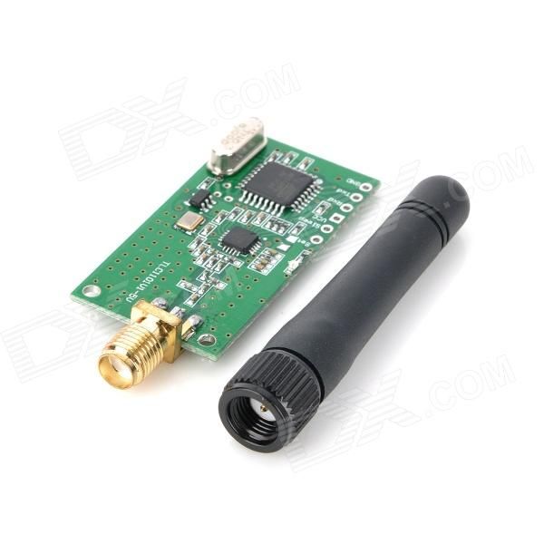
I have been looking into upgrading my radio systems. I have found the following on ebay. They indicate they are for ARDUNIO but do not know if they can be used on NERDKITS. I need one as transmitt and four to receive the same data. http://www.ebay.com/itm/10-Pcs-NRF24L01-2-4GHz-RF-Antenna-Wireless-Transceiver-Module-For-Arduino-/221343333799?pt=LH_DefaultDomain_0&hash=item3389173da7#ht_5868wt_900 Thanks Jim |
|
January 22, 2014 by Rick_S
|
Those communicate via SPI so yes, they do work with a NerdKit, just have to get the protocol down. I think Eric may have used these before, but I'm not sure. I have a pair, but never took the time to work with them. Worse case, you could probably grab the arduino library and parse the code you need from it. Most arduino libraries are written in C++ so they can be translated to C without too much effort. Rick |
|
January 22, 2014 by JKITSON
|
Thanks Rick.. For the price I think I will by the 10 lot to have spares. Will experiment with them and see how they work. Have not used SPI yet so now is the time to learn. Jim |
|
January 22, 2014 by mongo
|
I bookmarked that one here. If it works with ardunio, it ought to work with NK, |
|
January 22, 2014 by JKITSON
|
MONGO I have been having interferrence problems with the 433. We have a steel salvage yard close by that uses 433 for control of their crushers.. So thought I would try the 2.4. I also ordered some 1117 3.3 voltage regulators to use with them. Jim |
|
January 22, 2014 by BobaMosfet
|
coughs I have LM1117T 3.3V @ 800mA LDO regulators in stock in TO-220 package... $1.26ea at this time. Yes, I know, it's a shameless plug. :) BM |
|
January 22, 2014 by JKITSON
|
I did not forget. Was just starting to send you an email when your post came in.. Thanks Bobba your service and prices have been fantastic. Jim |
|
January 23, 2014 by Rick_S
|
Bobba, your store is up?? I didn't get an email Rick |
|
January 23, 2014 by Ralphxyz
|
Yeah, I didn't either! Ralph |
|
January 23, 2014 by BobaMosfet
|
Rick, Ralph, Everyone-- No, not visible yet, but we are a business, can take orders now. Just should me an email. If you tell me what you want/need, I can tell you if I have it, how much, or what it would take for me to get it. I'm working as fast as I can on the the site/forum issue, too. I will send official emails out when it's public. Meanwhile, don't be surprised if you start getting an email or two with photos, pricing, and whatnot for some of the items you might find useful, or hard to come by otherwise. Discounts I've previously mentioned to those that signed up, are still good. Warm regards, BM |
|
January 23, 2014 by BobaMosfet
|
just shoot me an email* BM |
|
July 07, 2014 by JKITSON
|
Hi all We had an Antique Tractor Pull on the 4th. The 10K pot worked perfect for setting the empty weight of each tractor prior to their pull. The display now gives me the following info: All done in real time with an ATmega168 chip. Now to install new 2.4ghz radio in the sled unit, and finish the remote units. Thanks everyone for your help. This would have never happened without all the HELP.. Jim |
|
July 07, 2014 by sask55 |
Jim I agree the support here on this forum I very helpful. I would like to see your sled in operation some day if I ever happen to be in the area when you are doing a pull. Locally around this area tractor pull where more common years ago now there is only the annual vintage tractor pull at the farm progress show in Regina, 60 miles away, in July. I have a number of friends that spend much of the winter in Arizona. I may be down in that area at some again this winter. Do you have a schedule of events that you may be doing pulls at this winter? If you are doing any pulls during the November to April time frame. If possible I would like to be aware of where you will be. If you could just drop me a note by email I would appreciate the info. I have no dates, if, or when I may be around your area but I would make a point of attending a pull if possible. dennis.darryl@ymailcom Darryl |
|
July 09, 2014 by JKITSON
|
Darryl I have sent an email. Actually sent two.. Jim |
|
July 09, 2014 by sask55 |
I have not received any email from you. Sorry ,I had left out the . (dot) in my email address. It is actually ymail.com. I sometimes do that thinking it may help to throw off any automated searches that may be trolling the net looking for email addresses. I don’t why I did it on this thread and not pointed that out, especially since I have posted that email address on this forum before and I don’t actually use that address for much. Darryl |
|
July 09, 2014 by JKITSON
|
Darryl I sent another email about 2 hrs ago. My email is JKITSON@CANYONCOUNTRY.NET JIM |
|
July 10, 2014 by JKITSON
|
Darryl I got your email. Sent a reply.... My phone# 928 645-3962 (home) Jim |
|
August 28, 2014 by JKITSON
|
Rick.. I finally found a USBASP programmer that worked. Your instructions for bootloader on the m238p were perfect. My program outgrew the 168 chip and now runs perfect with the 328 chip. The programmer I now have is the 3rd one. The other USBASP/USBISP programmers I could not seem to make work. Thanks again for your nice writeup. Jim |
|
August 28, 2014 by Rick_S
|
No problem, glad the old writeups can still be helpful |
|
September 02, 2014 by JKITSON
|
Need help.. I purchased some 2.4 gig radios for my sled project. I found that I had purchased units that use SPI interface. I have checked for other radios in the 2.4 area that use rs232 and cant seem to find any. Have done some reading & have not got my head around SPI. The units I got are NRF24LO1B. They appear to be pretty good with many places selling them. The SPI pins on my 328 chip are in use but can be changed & freed up. How do you write say 3 data fields of 5 digits to the SPI, and then on the other rec mcu read them out?. I have read some of the posts about SPI but most are using one master & many slave units. I just want to send data to one xmtr & read the data on another rx unit. Thanks Jim |
|
September 09, 2014 by JKITSON
|
Hi... If anybody wants these transceivers send me an address & I will give them to you. Have spent to many hours on trying to understand SPI. I have 10 of these NRF24LO1B units. No charge maby someone else can figure them out... Jim |
|
September 09, 2014 by esoderberg
|
JK, Here's some old code snippets from a working program that should give you the basics on setting up SPI. |
|
September 10, 2014 by sask55 |
Jim My experience with SPI is only between one micro acting as a master mirco and up to four mircros set up as slaves. I thought perhaps someone with more relevant experience and knowable may comment on your SPI question. After a quick look at the code esoderberg has posted hear I think that code will do essentially what you want without much changes. It has taken me some time to get a understanding of the basic concepts of SPI communication. I started with this thread by Noter and the Multi-Panel LED write up. Perhaps you are aware of these points but I will just go over a few points. I trust someone will point out any errors or misconceptions I may about SPI. I believe these points are demonstrated in the code used in each of the examples. I believe your radio units should be dealt with like any other slave for SPI comunication. Some things to remember with SPI are. The master and all slave devices are all connected one SPI bus all the time. All the communication goes to and from the MCU chip set up as the master to and from the other devices, no comuciaction between slaves is posible. The master can communicate with only one other device at a time. That one device is activated or selected for communication by a SS single from the master to that device only. Only the master can initiate communication on the bus, other devices must hold data until the master sets up the communication. When a data byte arrives at the slave device that device sends back a byte of data to the master. In order to receive multiple bytes from a slave device the master must send multiple bytes to that activated slave. The master may be sending only meaningless bytes just to trigger a return byte if there is one available on the slave device. If I was starting out trying to get a handle on this I would first up simple SPI using Noter’s thread, I found it very useful and informative. Then work my way trough the code esoderberg posted to try and set up the communications as you described. I am not certain any of this is of any help with your issue. |
|
September 10, 2014 by JKITSON
|
Eric & SASK55 Thanks alot. After reading the comments & trying to "digest" the code here and in Noters post I think I am seeing that SPI has to be Two-way communications between the master and slave units. For my application I was wanting only a one way data flow. I will keep transmitting the data from the Sled in a steady stream. When the pull is finished the data is put on hold until the sled operator does a reset & enters the new tractor weight. The remote unit should only receive what ever data that is sent from the Sled. Is my basic assumption of SPI logic right? If not I probably need to go back to first grade again.. Jim Thanks again guys. |
|
September 10, 2014 by esoderberg
|
Jim, As Sask mentioned, even if you only want to receive data via SPI, the SPI comms need to be initiated by the SPI master (by bringing the SS line low). The SPI transmission is duplex in that received bits on the MISO line come in concurrent with out going transmission bits on the MOSI line, so even when you are just looking to get data in this will be triggered by writing to SPDR and sending data out. Depending on the device you're interfacing with, what goes out on the MOSI line might not even matter. SPI isn't too tough after you've worked through it the first time, but every slave device will have a new set of registers and commands that can take some data sheet digging to get right. Eric |
|
September 11, 2014 by sask55 |
HI Jim I have bean looking over the Data sheet for your radio chips NRF24LO1B. I can see that setting up the data flow handling of your project would be time consuming for someone with my experience. About all I have determined for now is, It appears that the CSN pin on the transceiver is functionally equivalent to the SS pin on a micro slave. The CSN pin is pulled low to allow communication between the master and the radio. I think if I was setting out to do this I would take a long look at information available on the web regarding using the NRF24LO1B with an Arduino is one example. Since the Arduino may have the same processor it may be possible to locate source code in an Arduino library that will be relatively strait forward to adapt to your project. Or perhaps if one of the strong codeing members hear on this site gets on board you may get some valuable advice on how to set this up. I don’t think it would be that difficult to accomplish but would take some considerable time to get the timing and protocols correct. I took a quick look at a couple of examples of Arduino source code to accomplish communication, there does not appear to be a lot that has to be done. On the other hand it is not apparent to me what is being done with some of the code. This adaptation to your project looks interesting. Darryl |
|
September 11, 2014 by sask55 |
Arduino I will try this link on more time http://www.hobbyking.com/hobbyking/store/uploads/820169487X569826X26.pdf |
|
September 12, 2014 by JKITSON
|
Eric & Darryl Many thanks for the info & help... I am having to put off the remote radio again for this year as have run out of time. My goal is to have 3 remote units displaying the same data. One will be a small Nerdkits screen at the announcers booth. The other two will be 4" high by 15 character led displays. These will each have a receiver & Nerdkits 328P running them. I may be wrong but on the sled unit I have two magnetic sensors counting teeth on sprockets using two interrupts. It looks to me that the SPI code & the two way communications may slow the program down to where my interrupt timing would be affected. If this happens my footage & weight calculations would be off.. Just a thought.... Thanks again Your information gave me the ability understand a little better and make some choices. The 10 radios I have are still available to someone to use/play with. Let me know.. Jim |
|
September 15, 2014 by JKITSON
|
Hi all, The 10 radios are going to a new home... I have found another type & will try them.. These are RS232 interface. They claim 1 xmtr can talk to many rx units. We will see.. Thanks again for the help.. Jim |
|
September 17, 2014 by Rick_S
|
Hope the new home for your radios puts them to good use. I have had a couple of those modules sitting in a parts box for a couple of years and never really had a project that needed them enough to make me want to invest the time to figure them out completely. Maybe someday. Maybe the new radios you got will be easier to work with. Please keep sharing the info as you go, there are still a few of us out here that do regularly read the forum while it still exists. Rick |
|
September 17, 2014 by JKITSON
|
Rick The new radios are on the way from China. There must still be quite a few users on Nerdkits as the hit counter on the Tractor Pull thread is now over 10,000. I have looked for other sites and none come close to the greatness of this site.... Jim |
|
September 18, 2014 by Rick_S
|
Yeah, it's really a shame that Humberto & Mike just cast this venture away like dirty water. I really think it had potential and the closed forum for owners only I think really helped to keep the rif-raf out and kept the forums a friendly helpful place. That's probably why I still check them at least daily. Rick |
|
September 25, 2014 by JKITSON
|
I got my new radios in today. Will try this evening to test them then put into the sled computer & remote computer. Will keep all posted .... Jim |
|
October 07, 2014 by JKITSON
|
I did not have time to get the radios working before our tractor pull Oct 4th & 5th. But I would like to thank all who helped me get the unit modified to input the tractor empty weight. The 10 turn pot idea worked perfect both days. I now can tell the tractor driver how many pounds of weight he was able to pull and what the percentage of pull they did. All of our attendees were very happy with the instant information. Now on to making the wireless part work for the announcers booth and the large digital display unit for the public in the grand stands.... Thanks again Jim |
|
October 08, 2014 by sask55 |
Jim I have been thinking about what I think you are trying to accomplish with the wireless communication. I don’t really understand the details of the data you would like to send but there may be an entirely different approach you could look at. If the unit on the sled was set up to communicate with a lap top using the UART it would give you a virtually unlimited amount of flexibility and data storage capability. Individual results could be recorded as they happen. Now if that laptop was on a wireless network (wifi) with a second computer all the information could be entered stored and displayed at ether location. Information like tractor weight, drivers/ owner name, model number, ext could be entered prior to the actual pull, in advance. Any computer on your local network could make use of any part of this information that was required. Having a second lap top with the announcer in the booth could easily give the announcer access to all the information he will require immediately. The system could be set up to allow an individual on that lap top to send information back to the sled if that is desirable. The stationary computer could be set up to drive a display that was very informative and detailed if that would be desired. Result standings and other information could be included as the event progresses. As far as a large display is concerned I have found that commercially available units are very expensive to buy. Sunlight will wash out most displays when used outside. If where not for that issue I would seriously consider making use of a very large screen TV or a number of TVs. TV displays would be a simple and very flexible option. Most TVs could be set up as a second monitor on the lap top. It would be a straight forward way to show as much information as you like. When I was investigating displays I found that large screen TVs can be purchased for much less then even the most basic score/time clook type units. But I think that fact that your events are outside will wash out the TV picture and makethat idea useless. If you really got creative you could even consider posting results on an open wifi network or on a web page as they are recorded. That way anyone with a smart phone in the audience could follow the event details on there hand help devices. Darryl |
|
October 08, 2014 by JKITSON
|
Darryl The concept you refer to with PC'S is where I hope to get to. The next step is to get the UART xmtr & recvr to work. Once I can get the data from the sled to the remote box/pc to work the bell & whistles can come on line. At one time I had wireless working between the two units. (three years ago) I ended up with interference & have not had very good luck with any other radios. Has to be some dumb thing I have done. Computer & TV screens do not work for us as we are in the open with only shades over us. I had to take the laptop indoors just to enter tractors & print "pull" list. The Nerdkit's screens work very well in bright sunlight. Thanks for the ideas & concepts. Jim |
|
October 13, 2014 by JKITSON
|
I finally got the radios to work. The range check was over 200 feet. Data was 100% solid. After I clean up the programs some will post for anyone else to use. Will also post the info on the radios & the software setup program for them.... Missed being able to use them this year but will have them for next year. Now on to building the display board for the grand stands.... Jim |
|
October 24, 2014 by JKITSON
|
After 5 years I am now back to making this setup work. Have the hardware built. I do not think I have the 74HC164 chip wired to the mcu properly. Should pins 1&2 be wired to the MOSI of the mcu? Then send the "address" (ie 0-7) to the 164 chip. The goal is to select the display desired, have the data (digit) on the buss then issue clock signal to the 164 i think.. tell me if I am all wet.... thanks Jim
|
|
October 24, 2014 by JKITSON
|
The image don't come up. This is the same schematic prior in this thread.. Jim |
|
October 24, 2014 by BobaMosfet
|
Jim-- The 74HC164 is your 8-bit bus. Essentially, for control purposes the only pins you care about are 1, 2, 8, and 9. 1 and 2 are your control inputs, 8 is clock, 9 is clear. If you set CLEAR low, it zeros the bus. Doesn't matter what 1, 2, or clock is at. It will zero it on next clock pulse. To input a number, hold CLEAR high, and pins 1 and 2 accordingly. The only time a number is input is on the transition of the clock pulse. When you input, everything on pins 3-12 are shifted right, and pin 13's value is discarded. (it becomes pin 12's previous value). Pin 3 then is set according to pins 1 and 2: This has nothing to do with MOSI or the ISP or SPI interface. It's just TTL serial. You may use any 2 pins on your MCU to control Pin 1 or Pin 2. Hope that helps. BM |
|
October 24, 2014 by JKITSON
|
BOBBA.. Thanks for the lesson. You explained this much better than any of the "data sheets" I have read. I think now I have enough knowledge to be dangerous... Thanks again Jim |
|
November 05, 2014 by JKITSON
|
Here is the code for the remote unit that sits in the announcer area. It displays the tractor empty weight and the actual pull weight that is applied to the ground by the sled. The percentage is computed by dividing pull weight by tractor empty weight. The radio is connected the the serial port (mcu pin 2 rx) I do not use pin 3 tx here. The following code is part of the sled code that send the data to the radio transmitter. As you can see the code is very simple. The last line above does it all.. |
|
November 07, 2014 by JKITSON
|
Here are the radio units I used cc1101 232 rf1100. The following website has a very good program that can be downloaded to program the radios. These units are about $20 per pair on ebay. http://www.yesyes.info/index.php/electronics/rf1100-232-rf-433mhz-transceiver-module/
|
|
November 09, 2014 by JKITSON
|
Is there a function in Nerdkits/Avr that will convert a single digit 0-9 to BCD? I sure hope so... Thanks Jim |
|
November 10, 2014 by BobaMosfet
|
Jim, Likely there is a function in some library to do it... but I wrote this up, I think it'll do what you need. Just pass a number like '25' and it should give you a number back that is the BCD equivalent. I have NOT tested the function... but it seems to logically meet what you require. It's easy enough to test. An input of say, 25 should return a decimal value of: 37 (The hex and binary equiv's are: 0x25, 00100101) BM |
|
November 10, 2014 by JKITSON
|
Thanks Will give it a try this evening... Jim |
|
November 24, 2014 by mongo
|
Greetings! Been a little while, glad to see things are still happening. Jim, I am seriously going to look into these TX modules. I have never gotten mine to talk to each other and still need to get it working. Maybe this will do the trick? (I wonder if they are compatible with the old ones?) |
|
November 24, 2014 by JKITSON
|
Mongo I could not get the two to work together. I just received the second pair (now have 4 each). Be sure to go to the website & down load the program he made. Works like a champ. Mine came set at 9600 baud so that was what I used. I am xmitting on one & rec the data on the other 3 units. So far no errors. all 3 track with the same data. Has only taken me 3 years of off & on testing to make it work. Be sure to use the "X" in the xmt side and the while loop on the rx side. This seems to work fine. I am xmitting only numbers as data so any char would work but very few words start with a capital X. Hope this helps For the $40 I spent for these 4 radio units they work.... Jim |
|
November 29, 2014 by JKITSON
|
Here is the schematic for the Digital data display.
I will upload the program next.... |
|
November 29, 2014 by JKITSON
|
Here is the program to rec. radio data, parse data to single digits (5 for weight & 3 for percentage of pull). Then I use the 8 parsed digits to set up the 4 output ports that are common to all 8 digits. I then trigger the serial/parallel 74hc164 chip to select the proper 7 segment display. The loop runs 8 times to update all digits then gets new radio data and starts over.... I am performing the BCD conversion using logic & hardware. |
|
November 29, 2014 by JKITSON
|
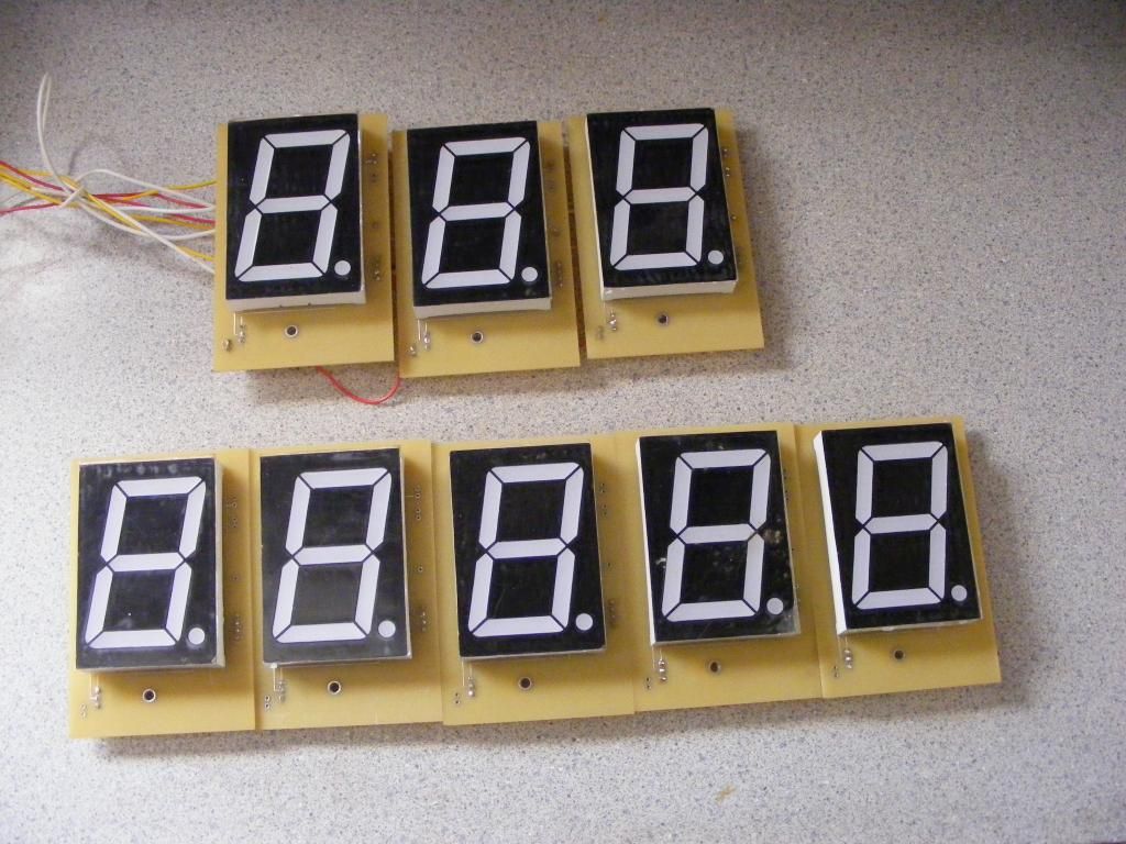
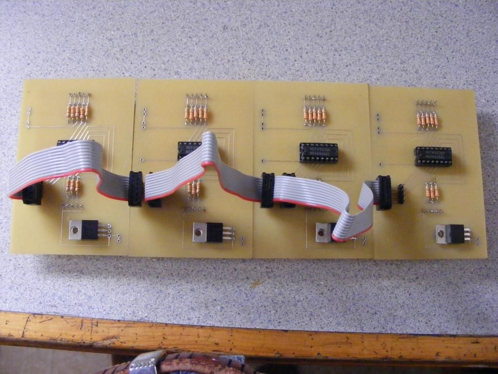
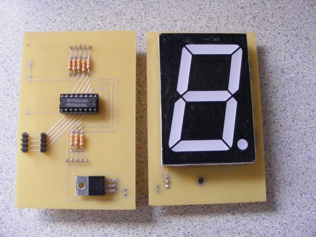
Here are the 7 segment displays with the pc board I had made. I am now building the cabinet to mount them in...
Thanks to all of you Nerdkit members for your help. I have made another step.... Jim |
|
November 29, 2014 by JKITSON
|
I will try again:
|
|
November 30, 2014 by Ralphxyz
|
Jim what you using to design your circuit boards? Are you having them manufactured? They look great!! I have a clock with ~2" seven segment Leds, anyone know here to get the modules besides tearing the clock apart? Ralph |
|
November 30, 2014 by JKITSON
|
Ralph I used ExpressPCB programs which includes the expressch for schematics. It was a freeware program off the internet. The PCB takes the SCH & creates a two sided board. I sent the PCB to them and had 30 boards made. I think my cost was about $90. I bought all my 7 segment displays off EBAY. In the past I have seen 2" units like mine there also. Thanks Ralph |
|
December 02, 2014 by BobaMosfet
|
Jim, Good work on this. I know how incredibly rewarding it is to design something and sit back and watch it work. A person often looks at such an accomplishment and can't believe they did it. And that's a very cool feeling :) Have questions: Line 77: Shouldn't that be "if(c)" instead of "if(c=1)"? c=1 is an assignment, not and test. As it is, it will always run the code inside the "if". Why did you require a regulator on each? I ask, because it looks like your ribbon-cable has enough conductors, it could have carried power on 2-conductors. Would have just required a couple more traces on the board (along with mount holes for a regulator)-- this would allow you to use each board either way. Wanting to see a video of it in action :) At least on the test bed-- very cool. BM |
|
December 02, 2014 by JKITSON
|
BM If you notice the line 77 thru 80 are rem'd out. Could not make that work. Your eyes are sharp to catch that. Would if(c==1) work? I only want to set the port to a "1" on the first time thru the loop (when c has a value of 1). The rest of the process the port needs to be "0". I will try this on my test setup. The reason for a voltage regulator on each is if all 8 segments of all 8 displays were on at the same time the total current would be approx. 1250ma. I chose to spread the current and heat out and use 12v supply to them. I also have plans on adding 5 more digits to the sign board. 5 for pull weight, 5 for tractor empty weight. and 3 for percentage of pull. With 13 displays I would be over 2 amp draw on a single 5 volt regulator. Thanks for your input. Jim |
|
December 02, 2014 by BobaMosfet
|
Jim, I see that they are commented out, now. I just got so focused :) - when you've code as long as I have, there are certain 'go to' things you just automatically focus on in code immediately-- whether or not one or two '=' is being used is one of those. Yes, you should change it to "if(c==1)" because right now, what you're doing is setting 'c' to 1 every time through the loop- so it will never be anything but a 1. I have some kingbright SA23-12EWA-N 2.3" 7-seg LED displays, like what you're using. So, I'm going off the datasheet from them, regarding power. Speaking of power, I understand now-- 64 segs * 20mA = 1280mA (1.28A). The LM7805 will support up to 1.5A, so it isn't a bottleneck. I would be concerned about the max output your MCU is capable of, because you are paralleling 4 of the outputs across the 8 displays. Have you run it? Does the MCU get appreciatively warm at all? BM |
|
December 02, 2014 by JKITSON
|
BM I am going to hook up all of them in a breadboard. Then we will find the smoke worms... Jim |
|
December 02, 2014 by BobaMosfet
|
Jim, Um... what is your breadboard rated for? If you try to use too much current on your breadboard, contacts will arc. This could go south really fast. At least go through a fuse, so if you get an arc, it will blow and you won't have a hot breadboard or fire. :: crossing fingers & wishing you luck :: BM |
|
December 04, 2014 by JKITSON
|
BM.. Also each regulator on the display's supply power to the HCF4511 decoder. I changed the code to c==1 and now that works perfect. I am building the permanent PC board for the sign then will test with all the 7 segment displays. I agree the breadboard might be marginal for this test. Thanks for the heads up on that.. Jim |
|
December 04, 2014 by JimFrederickson |
Hello Ralph, I didn't see an answer t your question from a few days ago. I think you were asking about geting "7 Segment LED Modules"? (I think that was the module that you were referring to.) I often get new ones from: Surplus from: Electronics Goldmine NOTE: Sainsmart doesn't actually have much of a selection of LED Displays, but they |
|
December 05, 2014 by BobaMosfet
|
Ralph, You can also acquire them directly from kingbright.com, they make them. I think they are about $3.57 each (or so) for the 2.3" red ones. There are other sources, too, so I'd compare pricing. I saw that kingbright also hs 4.0" versions :) BM |
|
December 05, 2014 by BobaMosfet
|
jkitson- I recommend you breadboard and use just one of your displays to start-- that limits your overall current and voltage requirements and lets you safely empirically determine a number of things. You can also use your DMM to measure the current, so you have a real value to compare against your mental picture. BM |
|
December 06, 2014 by JKITSON
|
I would like a couple more lcd displays. Does anyone know where to buy the NK type or have a replacement that works with Nerdkits? Any ideas appreciated... Jim |
|
December 06, 2014 by BobaMosfet
|
Jim, I sent you an email with imagery of ones I can sell you. BM |
|
December 07, 2014 by Rick_S
|
Jim, They are all over ebay for decent prices. Just search 20 x 4 LCD and you'll find them dirt cheap from china if you can wait, or for pretty good prices from US vendors. My latest displays I purchased direct from the manufacturer in China at www.buydisplay.com (I like the Dark blue text on the off white background). While I had a good experience with them your mileage may vary... They do sell on eBay as well as user buydisplay. Rick |
|
December 07, 2014 by sask55 |
Jim I have ordered 20 X4 LCDs as well as other size LCDs from china. As Rick said they can be very inexpensive. There are couple of things to keep in mind. The color of the displayed characters and the background colors can be considerably different. I think the darker displays seam easier to see in bright light. One of the orders I got worked well, but they do not have a backlight LED available on the display. After looking more carefully at the sellers add I noticed that backlight was not mentioned and I can’t get it to work on any of them on that order. Of the three orders I have made in the past they all work with the same command code instructions as the original nerdkit LCD. I also got a 20 X 4 LCD with a small piggyback circuit board included to enable I2C instructions to be sent to the display. At the time that display cost a little more then the regular displays did but should free up a number of pins on the micro.
Rick started a interesting thread about using I2C displays years ago Darryl |
|
December 07, 2014 by JKITSON
|
Thanks Darryl This helps Jim |
|
December 08, 2014 by mongo
|
The 4511's are handy. Been using them for 35 years +. I also have a few 4311's. Same thing but do hex readout. Jim, How long did it take to get the TX modules? The last time I ordered anything, it took almost 2 months. Nearly forgot that I even ordered them. Another time, I never did get what I ordered, so I had to find a different source. HI all! |
|
December 08, 2014 by JKITSON
|
Mongo The first pair came in 9 days.. The second pair took 6 weeks from the same vendor. I found some from USA but were about $40 each not $20 per pair. The 4511's seem to work very well for me. Once I strobe data to them they hold the value until next strobe. Jim |
|
June 26, 2015 by JKITSON
|
After a few months of trying to make the display work I found that I had laid the PC board out for a different chip than the 4511's. I have already installed the displays and most of the changes are underneath it. Sure have wasted many hours of programming to find it is hardware.. After the July 4th tractor pull I will decide how to attack this problem. The best to all & Happy 4th Jim |
|
June 26, 2015 by Rick_S
|
Bummer, It always seems the last place you look when trouble shooting is where you find the problem... Of course if I think about it that would always be the case because once you find the problem you quit looking... Anyway, I digress... Hope you have a good fourth too, and hope all goes well with the board repair. Rick |
|
August 07, 2015 by mongo
|
Like the definition of insanity: Doing the same thing over and over while expecting a different outcome. I tend to stop looking for something when I find it but once in a while, I find something else that sends me off on a tangent. The blessings of getting old... |
|
August 11, 2015 by JKITSON
|
Hi all Just got home from 8 days worth of ER rooms & Hospital beds. I lost usage of both legs & hips. The Dr's found during an MRI of my back & hips that something was not right in my right kidney. They found it infected with cancer past the chemo etc stage, so now waiting till the first of next week to have it removed. They started me on a treatment to reduce the swelling in my leg mussels & they seem to be getting better today. Our trip to Wisconsin tractor show this year has been cancelled. This will give me more time for Nerdkits stuff. Thank goodness i can still think and type.. Jim |
|
August 12, 2015 by Rick_S
|
Wow, Jim, I pray that they get it all and you heal well. Will they do chemo after removal? Keep your strength up as best you can. Cancer is an evil thing. Do the doctors feel it's contained in the kidney and that removal of the kidney will get it all? Sorry for all the random thoughts, You just completely caught me off guard this morning with this news. At least the forum is still around here, and if you have questions I can answer, I'll be happy to help out. Take care of yourself, keep strong, and as soon as you are able, let us know how the surgery went. Rick |
|
August 13, 2015 by sask55 |
Jim I also am hoping and praying that your treatment and recovery will be as quick and completely successful. I know that there has been great progress in the treatment of many types of cancer over the last number of years. I know of a number of people that have recovered from cancer with great success. My father in law lived completely symptom free for over 20 years after a battle with a very serious cancer. His prognoses was not good but he defied the odds, So even in cases that are bleak there is still a possibility of remission or cure . I am certain that this must be a difficult and emotional time for you. In my limited experience with friends and relatives it seams a positive attitude can be a great asset when dealing with a serious illness, It is good to see that you appear to be keep up the positive attitude. Darryl |
|
August 13, 2015 by JKITSON
|
Thanks all.. I have watched to many of my friends go this path & not survive. I have commented many times that their attitudes was to just give up. My theory was to look for good and go after it. Looks like the time has come to quit preaching and try living what I have been preaching. I have been living with CLL (chronic lymphatic leukemia) and Diabetes for over 7 years now. This is only one more step in life. Thanks again all Jim |
|
August 13, 2015 by BobaMosfet
|
Jim You are in I and my family's thoughts and prayers. Do not go quietly. And if you can, do not go at all. BM |
|
August 17, 2015 by Rick_S
|
Jim, What day this week is your surgery? Please let us know as soon as you can how things went. As Boba said, you are in our prayers. Rick |
|
August 17, 2015 by JKITSON
|
As of this morning (Mon) the VA has come thru with a total of "0". Thanks for asking & will let all know when & where. Jim |
|
August 18, 2015 by JKITSON
|
Good morning all (Tue) The VA has me setup for two full body cat scans on Wed afternoon. From there they will then decide when & where to go. This sounds promising. The hospital & Dr are 140 miles away so will try to post along. Thanks again all. Jim |
|
August 19, 2015 by Rick_S
|
I pray the Cat scans come back with good results, and that they can remove what is needed to get you back up and running. You'll be in my thoughts and prayers today Jim. Rick |
|
August 23, 2015 by mongo
|
Jim, You are certainly in thoughts and prayers here. |
|
August 25, 2015 by JKITSON
|
Hi all The two CT's show no spread or other cancer. Very good. The VA's "check list" says they missed having a kidney Dr. verify that I do really have a kidney & that is has cancer. So they canceled the office pre op with surgeon and now cant find a kidney Dr. until Sept 17. My VA Dr. is mad so at this point I am on hold. Thanks all for your thoughts & prayers. Will keep you updated Jim |
|
August 26, 2015 by Rick_S
|
Well, that's good news about it not being spread, but having to wait over two weeks to see the kidney Dr. really stinks. You would think if it were urgent, they would find someone. Wouldn't you need an oncologist more than a kidney Dr. anyway if they suspect kidney cancer, or are they looking for an oncologist that specializes in kidney cancers? Anyway, keep up the spirits and I'll be keeping you in my prayers and thoughts. Be well Jim. Rick |
|
August 26, 2015 by JKITSON
|
My oncologist has already said to get it out. This is probably normal for the Federal Govt's policy and procedures. Any way I am still in there with good spirits and ready to get back to normal. Have many projects waiting my attention. Thanks all Jim |
|
August 29, 2015 by JKITSON
|
Good morning all UPDATE The surgeon say's he will NOT operate because of my age, leukemia, diabetes & heart condition. Sounds like I have already passed on but am still here. They are going to go in thru by back and "Freeze" the cancer by injecting liquid nitrogen or argon. So sounds like this may be the best route to go at this time... Thanks all will keep you updated Jim |
|
September 02, 2015 by BobaMosfet
|
JKITSON- Thanks for the update-- our prayers and thoughts continue to be with you for a best outcome. BM |
|
September 30, 2015 by JKITSON
|
I had the cancer FROZEN on Tue 9/29/15. Was awake the whole time. No pain, soreness, or anything. They let me come home today 9/30/15. The Dr said he is sure he got it 100%. Totally amazing. Thanks all for your support & I wont hi-jack this thread any more.... Jim |
|
September 30, 2015 by sask55 |
Jim That is really good news. I hope everything continues to go very well for you from this point forward. Darryl |
|
October 01, 2015 by Rick_S
|
That is fantastic news!!! So glad to hear that. Are there plans for any follow up treatments, or just check ups every 6mo to a year? BTW, it's your thread so technically you aren't hijacking it in my opinion... And, even if you were, no-one here is going to scold you for doing so especially for the subject matter you interrupted it with. Here's to many more years tinkering... Rick |
|
October 01, 2015 by Ralphxyz
|
Great news!! |
|
October 02, 2015 by BobaMosfet
|
Indeed-- best of news. BM |
|
October 05, 2015 by JKITSON
|
Hi all.. I wanted to wait about a week before answering some of you questions. This last week has been a very busy week. We were setting up for our annual Antique Tractor Pull for the weekend. I spent 10 to 12 hours each day at the field as "boss" to get things ready. Our announcer could not make it so I spent both days announcing & answering questions to the public. Was at the show at 6 am each day to help cook breakfast for all the helpers. I have had "0" pain or trouble from the cancer freezing. The Dr said my body will naturally absorb and dispose of the residue from the freezing. The only restriction was no lifting heavy items. So far anyone I have told this to had never heard of it. Now I can concentrate on finding out what is wrong with my hips. I got thru the last week on steroids and oxycodone. My Nerdkits sled monitor worked 100% for both days of the pull. My remote monitor for the announcers stand got very wet during a rain in July. Have not been able to get a new chip programmed for it as my Nerdkits PC died. Am setting up an older Vista just for Nerdkits and the vinyl sign cutting unit I have. Jim |
|
October 06, 2015 by Ralphxyz
|
Go Jim!! |
|
October 08, 2015 by JKITSON
|
Over the past 6 years I have installed Nerdkits on several PC with no problems. My old PC with the setup on it died so am setting up a Dell 745 using Vista Pro. I make sure to use Admin to install all pgms. I have downloaded the Vista PL 2303 drivers. I get the blasted not avr910 etc error when running make. Am beginning to think my Nerdkit Usb programmer is bad. Have tried 3 different breadboards that worked in the past. Any ideas appreciated. I have read thru the multitude of posts here on NK and still no success... Jim |
|
October 08, 2015 by BobaMosfet
|
JKITSON- In the control panel, under account/personal profiles, you may find you can activate the true system administrator account, which may or may not help you. Otherwise, you might try these drivers instead-- other people have had better success with them:
BM |
|
October 08, 2015 by edSky |
I had luck using the "AVR 10 Pin USB Programmer 3.3V/5V 51 ATMEGA8 w/ Cable & adapter USBasp USBISP" in found on ebay For less than $7 it may be a solution. I still use the PL 2303 but have been thinking in the last day or so of just using the USBasp from now on. |
|
October 21, 2015 by JKITSON
|
Well I just proved to my self that MURPHY still lives. Built up a PC with Vista pro 64 just like I have used in the past with no problems. Bought new PL 2303 interface. Installed WinAvr multiple times. Still get the same Avr910 errors. Then the light started to shine... Tried a 328p programs fine. I can program 168 "WHEN" I change the make file in Libnerdkits folder One simple thing and only 3 months to find.... This is one I am ashamed to admit to but may help someone else down the road...... Jim |
|
October 21, 2015 by BobaMosfet
|
JKITSON- Don't be embarrassed. The more knowledgeable someone is, often the more likely the little things get overlooked. It's why I start with basics-- I know it adds clutter with some of the discussions here, but I like to start from some beginning things and try to not make assumptions when asking questions. BM |
|
October 22, 2015 by Rick_S
|
Yeah, it's often the simplest things that get us. Point in note, My boss, the son of the owner of the company I work for, went on vacation to Florida. Him and his dad do most all the electronic repair of the CNC machines at our shop with me tagging along often to help out. I love it because I get to learn a lot about the machine controls inner workings. So my boss had repaired a problem on one of the machines the Friday before he left (It had a monitor issue). Monday I come in and the machine is down again, reporting an OVERLOAD error on the screen, and won't move any AXIS. The owner asks me to help him troubleshoot it. So we start tracing down the circuit that would generate the error and everything looks right, but for some reason the machine doesn't seem to be reporting certain information it would normally pull from it's hard disc. Long story short, we go all the way to pulling the hard disc and replacing it, only to find after working on it an entire day that the main cable from the I/O module to the PLC had worked loose and come unplugged. So without that, the machine had no Idea what was going on in the outside world. If we'd just checked cables first, we could have had the machine up and running in minutes.... What get's me is, I know better. That's pretty much rule #1 check the simple stuff 1st. But, as you've found out, and I was reminded, we don't always do that, and it usually results in a bunch of time chasing our tails... Glad you found your problem Jim, now you can get on to the more fun stuff... Rick |
|
October 22, 2015 by JKITSON
|
Thanks Boba and Rick Remind's me of the saying "Cant see the forest for the trees" We had our sled in Flagstaff, Az for their show in July. A quick cloud burst caught my remote monitor at the announcers stand and flooded it. It had a 168 chip. Anyway now all my projects are going to be 328p chips. Jim |
Please log in to post a reply.
|
Did you know that microcontrollers have two different kinds of memory, program space (flash) and SRAM? Learn more...
|


Copyright © 2013 by NerdKits, L.L.C.

 HERE IS THE WIRING OF THE REMOTE UNIT


 JKITSON: I think you were linking to a PHP page, and not just the image.