NEW: Learning electronics? Ask your questions on the new Electronics Questions & Answers site hosted by CircuitLab.
Microcontroller Programming » Real Time Clock with Maxim DS3232
|
January 30, 2011 by Rick_S 
|
Well, as I mentioned in another thread, I got a free sample Maxim DS3232 RTC chip with onboard crystal and temperature. I've now got the project to a point where I thought I'd share. Before you all yell at me, I know, I used an Arduino... However, I programmed it in standard C. There is NO arduino code in this. I used the TWI (I2C) library from Peter Fleury ... no sense in re-inventing the wheel. Other than that, the code is mine with influences from snippets on the web. This code should work with the DS1307 as well minus the temperature reading part. Here is a shot of the displayed output on the LCD.
Here is a shot of the breadboard with the DS3232 and battery backup.
The LCD is connected via the standard Nerdkit hookup, the RTC is connected to pins 27 & 28 (SDA & SCL), the buttons are connected to PB0 & PB1 to ground. The code is pretty long and I'm sure it could be greatly optimized... but anyway, here it is. Besides this code, you'll need the i2cmaster.h and twimaster.c from Peter Fleury (google search... it's easy to find). Have fun with it guys... Rick |
|---|---|
|
January 30, 2011 by Rick_S
|
Here's a couple more photo's showing the set modes for time and date. The two arrows shift side to side with one button, and then make the selection with the other button.
Rick |
|
January 30, 2011 by Ralphxyz 
|
Great timing Rick, I need to have a Date\Timestamp for a project and the thought of getting time out of the RTC project seemed rather intimidating to say nothing of getting Day\Month\Year plus dealing with leap year. That just seemed like more than I could handle. So I bought a ChronoDot from the Evil Mad Scientist. This is made by a company called Macetech you get a newer version buying direct. The reasonI I went with the ChronoDot was I have not yet learned how to use Eagle to make up a PCB circuit nor have I ever made a PCB plus I am not sure if I have my SMD (surface mount device) soldering skills refined yet to the point of doing a project. With the ChronoDot all you have to do is add some supplied header pins and with the older ChronoDot from the Evil Mad Scientist solder the battery on to the dot PCB (which you do not have to do if you do not want battery backup). The clock chip is a DS3231S (DS3231SN on the newer version). I was going to start with your Nunchuck code and the expanded LED array both of which use TWI (I2C) but now I can just cop your code. THANKS SO MUCH!! Oh if you had done this as a Arduino you would/could have used Wire.h and cut your code by 2/3rds. I was going to ask if there was any way to use Wire.h as it appears to be a C header file. Please post some more pictures I want to see how you used the Arduino board. Oh, the ChronoDot cost $15.00. Ralph |
|
January 31, 2011 by Rick_S
|
I know there are ton's of arduino examples out there, I just have trouble wrapping my head around taking steps backward into the arduino world. The whole reason I went with a nerdkit over the arduino environment was to learn C. While arduino is built around a C/C++ framework the programmer is one step removed. I also wanted to be able to say... I did it. Not just to copy someone elses work.... Not that I mind if anyone copies mine... by all means have at it... That's why I posted it. :D Now I won't lie and say it is 100% without outside influence, I referred to several snippets on the web for the menu idea, the steps to read and write, and method for converting bcd. My goal was to make code that someone with a Nerdkit could load up with a little effort, and customize to thier own projects. As for the wire.h include for arduino, like most arduino libraries, it's written in c++. The library I did use from Peter Fleury does pretty much the same. Also, if you had Peter Fleury's library configured with the Nunchuck, it should work for the RTC, as I just copied those two files from my nunchuck project to the RTC one. Most of the bulkiness comes from the displaying of the data, with the largest section of the code to build and operate the time/date setting menu's. Those are 100% my code and I'm sure they reflect my green C programming skills. :D I looked at the ChronoDots when I was looking for a better alternative to the DS1307. I almost bought one then I read somewhere that Maxim IC has a very lenient sample policy that is hobbiest freindly. So, I set up an account, and ordered a couple samples. They shipped them, I put one on a SOIC to DIP adapter board from sure electronics as you see in the photo, and the rest is history. BTW, The code should work on the 3231 as well. The temperature reading should work on that chip as well. I think the only difference between it and the 3232 is that the 3232 has some battery backed SRAM. I haven't thought what to use that for yet but it might make a great place to store some varibles that could be saved when the micro is shut down. Happy programming, Rick |
|
January 31, 2011 by Rick_S
|
Oh, you mentioned time with the expanded led array (which I believe used SPI not I2C).. but anyway.. My goal was to put this on an LED matrix board from sure electronics I bought two of them and that will probably be my next step... Gotta take a bit of time away from the project though, the wife is starting to look at me funny when I'm sitting on the couch programming and looking at my LCD to see if it's doing what it's supposed to. Let us know how yours goes! Rick |
|
January 31, 2011 by Ralphxyz
|
Now this is strange (surprise surprise). How the heck does one invoke (use) twimaster.c?? For the NunChuck project I just copied twimaster.c to the project root folder and never thought about it. I only compiled the NunChuck.c code never touching twimaster.c and the program ran. Was that correct? Hexorg is helping me understand how to invoke a header file and he gave me a avr-gcc command to use to invoke a additional .c program "avr-gcc main.c pulser.c -o upload" (gee, it would be nice to have a [quote] [/quote] function). So step by step now what is the flow? Ralph |
|
January 31, 2011 by Rick_S
|
I think I posted the makefile I used at the time with the code. I'm at work right now but if you need it, I'll post it when I get home. |
|
January 31, 2011 by Ralphxyz
|
I used your makefile from the NunChuck project and the code compiles but nothing appears on the LCD it's completely blank! Ralph |
|
January 31, 2011 by Rick_S
|
I'll look to see if I changed something... I may have sped up the i2c clock. You could try changing that in twimaster.c. I think I had it slowed way down for the nunchuck. Try making it 400000. Rick |
|
January 31, 2011 by Rick_S
|
Something else you might want to check, I didn't have a definition at the top of the program for F-CPU. You may need to add that because if it isn't defined, there is a check in twimaster.c that will define it. I don't know what your twimaster.c defines it at but I think it defaults to 16mhz. Which would throw LCD timing off. Here is the makefile I have been using with this project in case you were interested. I changed the programmer type to arduino because that was the bootloader on the chip I was using. For the NK bootloader, you'll want to change that back to avr109. This makefile will also allow you to use the Make all (just compiles), Make clean (deletes all compiled files), or Program (comiles and uploads to chip) options in programmers notepad. I almost exclusively us that for my editor. Hope this helps get you going, Rick |
|
January 31, 2011 by Ralphxyz
|
I had to change my LCD. Now I get the two black bars in run mode. This is without the ChronoDot board. The clock change goes on line 21, correct? // I2C clock in Hz // Wants to be: Ralph |
|
January 31, 2011 by Ralphxyz
|
I had to change my LCD. Now I get the two black bars in run mode. This is without the ChronoDot board. The clock change goes on line 21, correct? // I2C clock in Hz // Wants to be: Just to add to my aggravation I have lost the Build options in Programmers Note pad. Windows 7 was reporting problems finding pn.exe when I would click on the Programmers NotePad icon. I downloaded a new version but it lacks the Build options I think I need to re-install WinAvr. Ralph |
|
January 31, 2011 by Rick_S
|
Could be, also, when installing, make sure you do it as administrator (right click run as administrator) otherwise programmers notepad and some other things like the environment paths don't get setup properly. rick |
|
January 31, 2011 by Rick_S
|
Yes, that would be the line to change for the I2C bus speed. Don't forget the F-CPU definition as well. Rick |
|
January 31, 2011 by Ralphxyz
|
I am "trying" to use your MakeFile and I get this error: Of course I got the notorious "No Separator" found message so I added tabs to every indented line. Now this. Where is a reference to DSS3232.c coming from? Ralph |
|
January 31, 2011 by Rick_S
|
That was the name of my program file that I listed above. |
|
January 31, 2011 by Ralphxyz
|
Ooops I found the answer as soon as I posted my previous question. Your program is named "DSS3232". I changed my file name to match yours. Ralph |
|
January 31, 2011 by Ralphxyz
|
Rick, if I load the InitialLoad program it loads and runs fine. If I load your code I get stuck with the two black bars. So the breadboard and wiring "appears" to be correct. There is something about your program that I can not run it. I suspected it has something to do with using PB0. But I loaded the .hex file using a programmer not the boot loader and get the same results. Ralph |
|
January 31, 2011 by Rick_S
|
Maybe move the I2C initialization below the LCD Stream setup and lcd_clear_and_home statement to see if it's getting hung on the I2C init. |
|
January 31, 2011 by Rick_S
|
Did you get the F_CPU added in? |
|
January 31, 2011 by Ralphxyz
|
Yes, I added the F_CPU. twimaster.c had it correct also. I just went through your code line by line you really did a outstanding job. Ralph |
|
January 31, 2011 by Rick_S
|
Thank you for the compliment, I would think a little better if it would work for you. I'm not quite sure why it won't. I may have to try to build up a NK circuit to test it on. Though I don't know why it would be any different other than the arduino runs at 16MHz instead of the 14.7456MHz. The micro is the same and there isn't any other supporting circuitry. My wife is getting a little frustrated with the projects eating up so much time though ... :D Rick |
|
February 01, 2011 by Rick_S
|
Well Raplph, I was curious after all the conversation last night. So I got up a little earlier and connected everything to a NK atmega168 with a 14.7456MHz crystal. Same connections for buttons etc. I changed the F_CPU value for the new crystal speed because the arduino was at 16MHz. Otherwise the program remained identical. I changed the micro in the makefile from a 328 to a 168 and changed the programmer type back to avr109. The program transferred fine, and ran without a hitch. I'm not sure at this point why it won't work on your end. ???? Rick |
|
February 01, 2011 by Rick_S
|
Here are a few photo's of the program running on a NK ATMega168.
Rick |
|
February 01, 2011 by Ralphxyz
|
I had been using your makefile from the nunchuck project. I then used your new makefile "BUT" had not noticed the AVRDUDE m328p designation. This gave me the two black bars in run mode. I changed the m328p to m168 (2x). Now I am back to where I was using the nunchuk makefile a blank LCD. Nothing. There is just the slightest flash of the two black bars at startup and then zip. Ralph |
|
February 01, 2011 by Rick_S
|
Just in case you have something different in the twimaster.c and i2cmaster.h files, I'll post the ones I used on the true NK chip when I get home from work. That way there will be no difference. Another thing you might try in the mean time would be to delete the *.o files in the libnerdkit folder to be sure they get compiled fresh. I may have a day off work tomorrow... We're under a blizzard warning from now until 4PM tomorrow... They are saying 15 - 24" of snow with 30 - 50 MPH winds. Could be interesting. :D Rick |
|
February 01, 2011 by Rick_S
|
Ralph, I sent an email to your gmail account. If you get it, let me know if that gets your project working. Rick |
|
February 01, 2011 by Ralphxyz
|
Thanks Rick, I got your email. I'll work on this tomorrow. "They" are saying we will miss the snow and only get the ice and rain. I would much rather have the snow, I hate cold, wet and icy winters. Bring on the snow, I just got a new snow blower two weeks ago and I was able to repair my 4x4 from a tip I found on line so I would much rather have 2' of snow than 1/4" of ice. Ralph |
|
February 02, 2011 by Rick_S
|
I don't have a 4x4 and live in a rural area 30 miles from where I work. My county declared a state of emergency and closed all county roads... Definately have the day off. I pulled my snowblower out Sunday and replaced the side ski's on it and the scraper blade. So it's good to go... Once the snow stops later today I'll be out there moving it out of the driveway so once the roads are clear I'll be mobile again. I agree with you, I prefer the snow over the ice any day. |
|
February 02, 2011 by Ralphxyz
|
Rick, when I run make this is all I get: Is this correct? When I switch to Run mode I get the two black bars no program. This is running your code you sent me. Ralph |
|
February 02, 2011 by Rick_S
|
Here's what I get doing a Make All from within programmers notepad running in Windows 7. This photo shows the versions of make, avr-gcc, avr-objcopy, and avrdude I'm running.
There has to be a difference somewhere causing the issue. Because the email I sent contained the actual program I have running on a 168 based Nerdkit micro. I saw you were compiling on your mac-mini... maybe the tools are different (older/newer) versions and are causing the issue. Did you try to just upload the hex that was already compiled? Rick |
|
February 02, 2011 by Ralphxyz
|
I have tried switching between my MAC and my Windows 7 computers. I will stick with the Windows 7 until I get this running! I did not try your .hex. This is progress I now can use Programmer's Notepad [WinAVR] Program, yesterday I was getting the same as I posted above using the command line. Now it runs all the way through. I still get a blank LCD. Here is what I get with [WinAVR] Program:
This is the first time I tried Programmer's Notepad with your latest code. Ralph |
|
February 02, 2011 by Ralphxyz
|
My versions of make, avr-gcc, avr-objcopy, and avrdude match yours. Your Make All almost matches my command line make: Except for line 4 I get the same results as you using [WinAVR]Make All. If I had the initialload program installed it would not be overwritten! Now with [WinAVR] Program the initialload program is overwritten. Ralph |
|
February 02, 2011 by Rick_S
|
Have you tried deleting all *.o files in both the project folder and the libnerdkits folder? |
|
February 02, 2011 by n3ueaEMTP 
|
Rick, Thank you so much for posting this. I've been looking for something like this (a non- Arduino C code RTC example) for a long time. The only problem I'm running into is that I cannot seem to get the twimaster.o file to show up. Everything is in the same folder on my hard drive except the ../libnerdkits files. Here's what I get when I run make from programmer's notepad: Any ideas would be greately appreciated! Thanks Chris B. |
|
February 02, 2011 by Rick_S
|
Chris, Did you use the makefile I listed in the thread? It should create the object files automatically. Rick |
|
February 02, 2011 by Ralphxyz
|
yup, done it again! [WinAVR] Make All makes all of the .o and the .hex. Ralph |
|
February 02, 2011 by Rick_S
|
Ralph, still a no go on the LCD I take it? This has really got me stumped. |
|
February 02, 2011 by n3ueaEMTP
|
I was using a modified NK makefile that has always worked in the past. I tried your makefile with a few revision (I'm using the sparkfin USBtiny programmer) including Ralph's tab solution. Here is the revised makefile: And here is the new output from PN:
Thanks so much for taking the time to help !!! Chris B. |
|
February 02, 2011 by Ralphxyz
|
Wow, after doing a number of program loads using the command line and Programmer's Notepad I loaded the initialload program confirmed it was running and then from the command line programmed the DS3232 program. Now I get this:
This is the first time I have gotten anything on the LCD. Ralph |
|
February 02, 2011 by Rick_S
|
Ralph, Does your Chronodot have the 4.7K pullup resistors installed or are the spots unpopulated? |
|
February 02, 2011 by Ralphxyz
|
That was a fluke, the initialload program was still loaded on the mcu. Now I am just getting the two black bars. Darn, I liked getting the ?? marks. Ralph |
|
February 02, 2011 by Rick_S
|
Looking at your board, it appears the silkscreen spots for them are empty. If they are not there, you need to add 4.7K pullup resistors to both SCL and SDA. The I2C spec requires the two lines be pulled up. Most peripherals do not do this themselves so you don't end up with multiple pullups. Maybe this is creating a bad read situation that is causing the display to garble or the program to lock up. Rick |
|
February 02, 2011 by n3ueaEMTP
|
Not sure what I did but it is now working!! :) I'm using the DS1307 instead of the DS3232 so I don't have the temp reading but that's OK by me. Rick, please send me your email address to medic122 (at) n3uea (dot) com. I'd like to send you and your wife out for dinner. Thanks again. Chris B. |
|
February 02, 2011 by Rick_S
|
Thanks so much for the offer Chris, I'm just happy to know it worked for you. Ralph has had a bunch of trouble trying to get it to work and I was beginning to wonder if there was something special about my setup. Was your setup the standard NK setup? Rick |
|
February 02, 2011 by Ralphxyz
|
I am seeing stupid things with loading other programs as well. From some programs I am getting the two black bars in run mode. Other programs load fine. All of these programs (besides Rick's) have loaded and run in the past. Also I am seeing 4.3 volts across the rails with no power applied. This has to be coming from the USB green wire (I have a switch on the yellow wire). I am setting up another breadboard. It's good to see that Chris got this to work. Ralph |
|
February 02, 2011 by Rick_S
|
Well I hope you can figure it out Ralph. Sometimes things can be tricky to track down. Rick |
|
February 02, 2011 by Rick_S
|
Ralph, did you ever add the pullups for the SCL & SDA lines? |
|
February 02, 2011 by Ralphxyz
|
Yes, I added the pullups. I need to figure out what is causing the two black bars in run mode. This has been discussed a lot in the forum but there does not seem to be one thing that does it. So how much snow did you get get? All we got was rain. Ralph |
|
February 02, 2011 by Rick_S
|
With all the drifting it's really hard to tell. It was over my knees in parts of my yard and I could see grass in other parts. The news is reporting about 16" in a nearby town. Here's a photo of my deck a little earlier today.
|
|
February 02, 2011 by Rick_S
|
Rain is a lot better than the ice you were talking about though. I know I'd much rather have had it than the snow. Someday I may have to move south and leave these snowy cold winters behind... :D Rick |
|
February 02, 2011 by n3ueaEMTP
|
Rick & Ralph, I am using the standard NK setup, sorta :-/ My main project doesn’t need serial communication and the two extra inputs are needed so I picked up a AVR Pocket programmer from Sparkfun and use that instead of the standard NK serial programmer. I don't have the NK bootloader installed but all the fuses are set the same. The crystal is 14.7456 and the power is coming from the programmer. Could Ralph's issues be due to the bootloader? My main project uses PB1 as an output so I need to move that button elsewhere, I'm thinking I'll use PC0 as that is currently used as an ADC for the LM34 which I won't really need if I use the DS3232 (I'm actually using the DS1307 right now). My biggest problem now is that I need to combine the RTC code with my current project code. I'm thinking I'll need to do some serious re-designing to lean the code a bit. Thanks again, it is much appreciated!! Chris B |
|
February 03, 2011 by Rick_S
|
I don't think Ralph was using the bootloader initially either. I've loaded it on two different setups, an arduino uno with an ATMEGA328P and arduino bootloader, and a standard NK ATMEGA168 with the Nerdkit bootloader. Both worked the same. I'm not sure what is keeping it from working for Ralph. I think he's investigating other avenues right now and rebuilding his circuit. As for leaning the code down, I'm sure that could be done. The Time/Date setting function is the largest part of the code by far. I'm sure someone with better C programming skills could shrink that down dramatically. I'm pretty green when it comes to making condensed code. The ChronoDot Ralph is using sports the DS3231 which will also provide the temperature output. The difference between it and the 3232 is that the 3232 also has 236 Bytes of SRAM that is battery backed as well. So if you had some variables / settings that wanted to be stored they could be store in that memory space and would survive a power outage. It could be used to store configuration variables as an alternative to using the eeprom. If you don't need the SRAM the 3231 could be a good alternative. Rick |
|
February 03, 2011 by Rick_S
|
I'm also glad to know the code works on the 1307. After looking at the datasheet for the 1307, I figured it would but it's good to have verification. Rick |
|
February 03, 2011 by Ralphxyz
|
I have switched between using the bootloader and my programmer. If I use the bootloader I get the two black bars in run mode. If I use the programmer I get the blank LCD. I am going to strip everything but the LCD output and rebuild the code backwards. I "should" either find the problem or end up with working code. Ralph |
|
February 03, 2011 by Rick_S
|
Definately let us know what you find out. I'm curious as can be to know why your setup isn't working like mine and Chris's. Rick |
|
February 03, 2011 by n3ueaEMTP
|
Rick, I have successfully combined your DS3232 code with my major project and all is running well!! I had disabled the USART previously to gain two extra input pins. I’ve moved the Get_Button_Status function to PORTD and am using PB0 as the alarm input when the ambulance call is received. I have another menu that changes some timing variables and that menu allows for up/down function instead of just up. The up/down buttons are a bit more convenient, but I might just remove my down button and use your up/cursor move button idea. It will save a pin but not a button as my cursor move button has another function when not in menu mode. In addition, I’ve added Jan, Feb, …, Nov, Dec in place of the numbers where the month is on the LCD. I’m also going to work on adding the ability to select 24 hrs in addition to AM/PM. In time, I’ll switch back to the DS3232 to add temperature ability because that will be necessary for the final build (it adds fan control for the power supply cooling). When I have these things completed, I’ll post the code here for anybody who wants it. Thanks again Chris B |
|
February 03, 2011 by Rick_S
|
The 24 hour time format will take a few modifications to the code. Mainly because I built the code around a 12hr format. In the time setting routine, possibly a 3rd option could be added form AM/PM Possibly AM/PM/24 and assign a variable to the 24 option. Then in the Hour setting section if the AM/PM/24 was in 24 mode the time could advance 00 - 23 instead of 1 - 12. Then when saved, bits 5 & 6 would have to be written to reflect either 12 or 24 hour mode. After looking at the code a bit more, that would probably be the only area that would need changed. I was originally planning on doing 12/24 hr. Just didn't when I wrote my setting routine. When it displays the time, I accounted for it. If you need any help with changing the setting routine, let me know. Glad to hear it worked well in your project. P.S. The only reason I programmed two buttons was because I had that two button board laying around that I had salvaged from an old scanner. I didn't have a 3 button one :) Rick |
|
February 03, 2011 by Ralphxyz
|
Darn it "almost" works:
No one would believe what I did to get this far. I have not pushed any buttons or dared to turn it off and back on so the display shows the same none changing info. Now here is what I did. I have had a problem (reported here on the forum) with the voltage on the yellow USB wire holding teh mcu in a zombie state (not able to run programs). So on the advise of Humberto I had put a switch on the yellow wire, this has worked fine. So this morning I "thought" (always leads to trouble) I aught to use the USB power and switch the power (red wire) with my switch which I already was using for the yellow wire since it was a double pole switch. So I added the wires to the other poles and plugged it into my bread board with the USB yellow and red. I inadvertently (not paying attention) plugged the power pole to GROUND. This of course caused mayhem on my computers (I of course had to confirm that it wasn't working for some reason so plug the USB cable into my other computer so both of them freaked out on me. Now I the mcu programmed with Rick's code but was only seeing the two black bars on the LCD when trying to run the program. I tried running the program with the switch miss wired (red to grn) and got a blank LCD. Finally after multiple reboots I saw my error and corrected my error. Then I turned the mcu on and voila you see the results! So now any suggestions, besides getting a good nights sleep? I'll keep you all posted. Ralph |
|
February 03, 2011 by Rick_S
|
Maybe press your reset button to see if it initializes the RTC properly. You do still have the pullups on the RTC right? |
|
February 03, 2011 by Ralphxyz
|
I set the time and the date (man Rick this works great) and turned the mcu on and off but I get the same Time/Date/Temp as pictured above. Obviously it ain't working. What to do, what to do? Ralph |
|
February 03, 2011 by Rick_S
|
This is very odd. So you can go through the setting routine but when you select save from the two menus nothing changes... the display stays the same as above?? This is very strange and it seems that it isn't talking to your RTC. If it were, I don't think you'd get the output you are getting. You didn't accidentally get your SDA & SCL lines crossed by any chance?? Rick |
|
February 03, 2011 by Ralphxyz
|
Rick, here is the Arduino sample code from the manufacture's site. Don't know if you could see anything with it but thought I'd post it. I do not have a Arduino programmer nor any knowledge of Arduino at all so I can not test it. If I installed Arduino I suppose I'd get wire.h so I wonder if I could make up a operable program by putting wire.h into the root folder of the project? What reset button? Ralph |
|
February 03, 2011 by Rick_S
|
wire.h is essentially to arduino what twimaster.c is to the raw c code we use. Honestly I'm not quite sure how thier code would work since they are using 0x68 as the address and the datasheet clearly shows the address is 0b11010000 (0xD0) for writing and 0b11010001 (0xD1) for reading. Which is what I use for the address. |
|
February 03, 2011 by Ralphxyz
|
You had said "You didn't accidentally get your SDA & SCL lines crossed by any chance??" The only thing I had to go by was: "the RTC is connected to pins 27 & 28 (SDA & SCL)," So I take that as SDA-27, SCL-28, correct? I have another mcu that I have loaded your program onto but with that I still get the two black bars in run mode. Apparently I have to short it in order to get the program to run. Ralph |
|
February 03, 2011 by Rick_S
|
Yep, SDA is 27, and SCL is 28... so that's right... I really wish I knew what was going on. I've successfully run it on two different micro's and Chris ran it on his. It's very peculiar. Rick |
|
February 03, 2011 by Rick_S
|
I see what they are doing in wire. The reason they use 0x68, is because they define the address as 7 bits 1101000 instead of 8 (11010000) which is technically correct but they have to shift their address and add the read or write bit (0 for write 1 for read) I just use the 8 bit version and add 0 or 1 which is essentially the same. Rick |
|
February 04, 2011 by n3ueaEMTP
|
Rick, I tried to modify your menu to add up/down buttons without success. To that end, I am rewriting the menu from scratch using the format I’ve been using for the other menu items. It has three buttons, up, down, and change position. I doubt it’s anything close to being efficient as yours, but it’s something I can understand. I am running into problems with the am/pm and haven’t even begun to touch on the weekday or month yet. Since this is for the fire/EMS service, I may scrap am/pm and just stick to the 24 hour mode. I am occasionally able to reproduce Ralph’s issue; at least I could for a few hours earlier tonight. If I would remove power, when I added it back, I would get black lines on line 1 & 3. The only way I could remedy the situation was to flash the program onto the MCU. As I write this, I can’t seem to reproduce the issue, all is working again. Chris |
|
February 04, 2011 by Rick_S
|
Interesting. I wonder what could be causing this to happen. Do me a favor, if it happens again, try this. In the main function, move the call to the DS3232_init() function below the LCD setup. So instead of being: It would be: That would have the effect of clearing the LCD before doing anything with the RTC. The only other thing I could think of, is there could possibly be some RF generated by the circuitry that is causing interference. Possibly additional filter capacitors may help... But that's just a stab in the dark. Rick |
|
February 04, 2011 by Ralphxyz
|
Rick, how did you get the free samples from Maxim? I have signed up at their web site and gone through the DS3232 pages but have not found a "Samples" offer. Ralph |
|
February 04, 2011 by Ralphxyz
|
I found it, if I get the sample I'll make up a board to match yours. What was the breakout board you used? Is there any other components besides the pull-up resisters? Ralph |
|
February 04, 2011 by Rick_S
|
I used SOIC to DIP adapters from sure electronics. I just checked their website for a link but they don't have them listed anymore. Any SOIC to DIP adapter board should work though as long as it has at least 20 pins for the IC. I didn't readily see any on e-bay either that were 20 pin but there are several 28 pin ones and you could just mount the chip at one end. Here are some close-ups of the RTC on the board. (I apologize for the dust on my desk and slight blur to the photo's... they were taken with my cell phone :D)
As you can see from the photo's, other than a bunch of jumpers to connect all the NC pins to ground, I only added the two 4.7k pull-up resistors, a .1uf filter cap, and a 10k pull-up on the INT/SQW pin in case I wanted to use it. The only other connection is the button cell battery, to the Vbat pin. Beyond that, on my setup I have the LCD wired exactly as shown in the guide, without the backlight. I have the two normally open button switches at PB0 and PB1 that each go to ground when pressed. The microcontroller is a Nerdkit original ATMEGA168 with their bootloader. It is wired exactly as shown in the guide except I place a reset button on pin 1 with a pullup instead of just tieing pin 1 high. I use a pretty well filtered breadboard power supply for my 5v to operate everything. I have no usb connection, as my pc has a true serial port that I use with my original NK serial programming adapter. Rick |
|
February 04, 2011 by Ralphxyz
|
Thanks Rick, I am thinking about making my own pcb using carbon paper and resist pen. I picked up a discontinued pcb kit from Radio Shack so I have the board and the chemicals. I need a drawing to actual scale. I should learn how to use Eagle in the mean time. Ralph |
|
February 04, 2011 by Rick_S
|
I've never used carbon paper. Resist pens from my experience are ok for minor touchups but I've never been good at making a full board. I've had some success using the laser printer method with board design in eagle. I etch with a hydrogen peroxide / muratic acid mix. It's pretty cheap and works pretty good for one-offs. Making your own board does give a sense of accomplishment. Make sure you have your design right though before etching. Once you etch, it's too late. :D Rick |
|
February 04, 2011 by Ralphxyz
|
Well it seems a 20 pin SOIC breakout board aught to be fairly simple. We'll see. Now back to my problem with running your code. I wonder if your using PB0 is causing my problem? I have problems running huzbum's RPM counter code because of his use of PB0. I changed the two usages of PB0 (lines 586 and 587) to PB2. Now I cannot change the date/time settings (thought they did'nt stick I could pretend to change them). Is there anywhere else PB0 is invoked? I am just starting to look at this. Ralph |
|
February 04, 2011 by Rick_S
|
PB0 and PB1 are defined at the top of the main function. They are then referenced by passing either a 0 or 1 to the Get_Button_Status function. If you change PB0 to PB2, you would have to call Get_Button_Status(2) in place of Get_Button_Status(0) anywhere it was referenced. Rick |
|
February 04, 2011 by n3ueaEMTP
|
Greetings All, I have finished my clock setting menu. Once you look at it and read the paragraph at the top, it should be pretty self explanatory. All the comments aren’t complete but the code gets the job done. There are still a few bugs to work out, but you’ll get the basic idea. Here it is: Chris' DS1307 Menu. I hope it helps someone. By the way, I stopped over at Maxim's website and they have been gracious enough to send me a few samples of the DS3232 and I found this SOIC to DIP Adapter 20-Pin at Sparkfun. I've ordered a few, we'll see how the soldering goes (wish me luck). Chris B. |
|
February 04, 2011 by Rick_S
|
I forgot Sparkfun carried the adapters... a bit pricey but with free RTC's from Maxim, It will make for a good setup. I'll have to print out your menu.. It's a bit long to follow easily on the web page. That way I can look it over to see if it sparks some more ideas :) Glad it's all coming together. Rick |
|
February 05, 2011 by Rick_S
|
Chris, Did the web formatting erase some of the program. It appears there are a lot of braces {} missing, especially opening braces. For instance, you have the statement With no braces after the while statement, what exactly is it doing? I also see else statements with no associated if statement. It seems like somehow stuff got lost in the formatting for the web?? Was this part of your main function, or is it a standalone function in your program? Rick |
|
February 05, 2011 by n3ueaEMTP
|
Rick, it must have becasue here is what is in the program: Odd, I'm not sure why that would have happened. Here is one of the programming sub loops: All of the loops follow this same patteren. Chris B. |
|
February 05, 2011 by Rick_S
|
I had a feeling something got lost in the web translation. I couldn't imagine it would have compiled the way it was reading. :) Rick |
|
February 05, 2011 by Rick_S
|
I modified the code a bit more. I didn't like the fact that the setting routine would allow for invalid dates. So I created a function that checks the date to ensure the day of the month doesn't exceed the value allowed for a given month accounting for leap year in February. Here is the function. And I call it from my time setting routine. Starting at line 507 in my original code posted above, replace it with this. You'll see the call to date_is_valid in the case 2: section. Hope that helps spark some more ideas... Rick |
|
February 06, 2011 by Rick_S
|
I made a few more changes. I added an LED to indicate when in set mode at PB3 (Anode to PB3, Cathode through current limiting resistor to ground), and another switch to PB2. This gave me an up button at PB1, down at PB0, and Menu selection/enter button at PB2. I modified the Get_Button_Status, DS3232_set_time and main funtions to implement the changes. Here are the new versions. The new Get_Button_Status() function no longer takes an input, it is hard coded to PB0, PB1, and PB2. It returns 0,1,2,or 3 depending on button pressed or no button at all. The New DS3232_set_time() and main() functions have been modified for the new buttons and to allow for up/down inputs. Any thoughts, ideas, or suggestions, as always are welcome. Rick |
|
February 07, 2011 by Ralphxyz
|
Rick, I finally confirmed something I had suspected. I am able to load your original code you sent me onto a ATmega328 and it runs!! No black bars in run mode!! Of course it is not talking with the the Chronodot (DS3232)but at least it runs. Now to get it to talk with the DS3231, I will make modification to the code using your new changes. Using the LED "should" give me some indication of establishing a connection. Ralph |
|
February 07, 2011 by Rick_S
|
It should talk to the Chronodot (DS3231) without any changes. The 3232 and 3231 are pretty much the same only the 3232 has 236 bytes of SRAM that is battery backed up. It's also odd that it wouldn't run on the 168. That is my current test platform for it. Did you try deleting the LCD.o file in the libnerdkits folder to make sure it got re-compiled? Rick |
|
February 07, 2011 by Ralphxyz
|
Gee, you have changed your looks. Yes I have done that in the past I did not do it for this test, I just wanted to see if it would run. I have other "running" programs that if I change from the 328 to the 168 will get the same two black bars effect. Is the address of the DS3231 the same as the DS3232? Ralph |
|
February 07, 2011 by Rick_S
|
Thought I'd try something a little different :D Yes the address for the 3232, 3231, and 1307 are all the same. This code should work out of the box for the 3231 on your Chronodot. Rick |
|
February 09, 2011 by Ralphxyz
|
Whoowee!! I just received 4 DS3232's as free samples from Maxim!! I had randomly ordered a bunch of breakout boards from SparkFun so I have the needed 20 pin breakout board. Now I have to try my hand at SMD soldering, hey Chris how did you do with the SMD soldering? What technique did you use? I have seen a number of tutorials on the web on soldering. In fact I have a Elenco soldering training kit that I have never completed probable I should do the training first. I have a Magnetic sensor Module (compass) and Barometric Pressure Sensor that both use I2C, so I am really hoping to get Rick's code working, then I can add the other modules. I am also going to be needing Data Logging and have been thinking of using a EEPROM using I2C instead of having to learn how to hook up a SD card it seems expedient to do the EEPROM that way I can just add another device to the que. Then I'll need to communicate with a ZigBee module using the UART to down load the data to a PC. Has any one done any thing using I2C and EEPROM? I suppose that question should be on a different thread. Well here we go, I'll be diving into the next step tomorrow. Ralph |
|
February 09, 2011 by Rick_S
|
Ralph, I don't know if you got it from his website or not, but if you go to Peter Fleury's website to get the I2C library, his sample test program is for an eeprom. I haven't tested it but I'm sure it would work. I had some other code around for eeproms because that was what I used to test my setup when I was playing with the nunchucks, I just can't seem to find it now :(. Rick |
|
February 09, 2011 by Ralphxyz
|
It was reading Peter Fleury's pages and code that got me thinking about using a EEPROM instead of a SD card. The convenience of using the SD card is that it can be moved over to a pc to extract the data but as I am picturing my weather station being mounted up on a pole out of ready reach it really would not be very handy to get to. I will be using ZigBee to extract (communicate) the data to a pc. I'll start another thread instead of hijacking this one further away from it's theme the DS3232 RTC. Ralph |
|
February 09, 2011 by n3ueaEMTP
|
Ralph, I too received my DS3232's today so I havent had the chance to do any soldering yet. I also need to get hold of the breakout board from sparkfun. I also need to get some flux paste as well. The tutorial I saw made it "LOOK" very easy, I doubt that will be the case on my first try. I'll keep ya posted!! Chris |
|
February 10, 2011 by Rick_S
|
I just used a small gage rosin core solder (Ø0.015"). I tinned the 1st pad w/o the chip there. I then aligned the chip and held it in place while melting the tinned pad to the pin on the chip. I then soldered the opposite corner. Then while applying light pressure to the chip, I remelted that corner to make sure the chip was seated. I then one by one soldered the chip down. That method worked for me... YMMV Rick |
|
February 10, 2011 by Ralphxyz
|
Chris, you should not need flux paste. Besides the problem of shelf life, refrigeration and cost I'd leave that alone. Wow Rick 00.015 solder is really fine. The SMT practice soldering kit I got is a Elenco SM-200K. You assemble a decision maker electronic board with smt resistors, capacitors, led and SOIC ic. There is nothing instructing you how to solder but for 15 bucks it seemed like a good way to start, plus it comes with 4 zero ohm resistors to practice with before you start with the actual components. The solder that comes in the kit is 0.031 Radio shack carries .032. There are a lot of soldering tutorials on the web I had one that was real clear and comprehensive but I can not find it now. They tacked down opposing corners and then laid the solder down the length of the ic and just flowed the solder. I believe the key is to use additional solder paste besides the flux core. Well I am definitely going to make up my decision maker so I'll let you know how it goes. Ralph |
|
February 14, 2011 by Ralphxyz
|
I got my DS3232 samples and I had a 20 pin SOIC breakout board so I made up a new module. I have not been able to use Rick's code using a Chronodot DS3231 RTC chip. So Here is my new RTC setup: Alas I am having the exact same problem, I can not save the date/time settings!! This is exactly the same as I was experiencing with the Chronodot. Rick, what button do you push for SAVE when setting the date/time? I assume it is one of the set buttons. re: the RTC chip setup the chip is on the bottom of the breakoutboard with the battery on top. This is how new Chronodot is assembled. The header pins I use have a spacer between the board and the pins so this gives lots of free space. The battery holder is from Radio Shack. I am using a ATmega328P as I never did get the ATmega168 to run. This is so mysterious. It has to be something I am doing or have not done. Ralph |
|
February 14, 2011 by Ralphxyz
|
Sorry about all of those image links at the bottom I did not do them, it's this stupid forum application doing it's thing again. Ralph |
|
February 14, 2011 by Rick_S
|
Did you tie all the N/C pins to ground? From what's on the display I'm not sure it's talking to the RTC. |
|
February 14, 2011 by Ralphxyz
|
I was wondering about the N/C and just now saw that you had put them to ground, I'll certainly do that. Ralph |
|
February 15, 2011 by Ralphxyz
|
I modified the program to only grab ret at the very start: ret is returned as 01, so what does this tell us? Is the DS3232 being communicated with? Ralph |
|
March 01, 2011 by n3ueaEMTP
|
Rick and Ralph, Sorry it took so long to get back to you guys. It was my week to work. Anyway, I now have 6 DS3232s and the breakout board. I have things wired per the datasheet and following Rick's pictures above with the 10K resistor on pin 5. I get either all 0s or all 11s. When I connect the DS1307 (which does work fine) the display displays the correct time/date. When I remove the DS1307 it returns to all 11s. It doesnt appear that I have any solder jumpers on the DS3232 breakout board. All this rambling brings me to my question: could the address be wrong on my DS3232? I've tried two DS3232s with similar results. Any ideas? Thanks guys Chris |
|
March 01, 2011 by n3ueaEMTP
|
Never mind, it was a poor solder job. Its working great now!!! Chris B |
|
March 01, 2011 by Ralphxyz
|
Darn, I glad it's working for you, I still having problems. Maxime's "Sample Program" is really generous. Also I am finding Texas Instruments to have a great Sample Program. Both even pay the shipping. Ralph |
|
March 01, 2011 by n3ueaEMTP
|
Ralph, i had to resolder the DS3232 on the breakout board. Thats the only thing I did differently. I had never soldered anything surface mount before this so I'm thinking thats the root of my issues. Could that have something to do with yours as well? Please don't mistake this for me doubting your abilities, just another idea as to what may be causing your issue. I think it was Rick that said something about how he tinned the breakout board with solder before adding the DS3232 so that's what I did on the third try and that did the trick. Chris |
|
March 02, 2011 by Rick_S
|
Hey Chris, it has been a while. How is the project going? I'm glad you got the problem with the DS3232 figured out. I just wish I could figure out Ralphs'. I know the frustration when something doesn't work as expected. I usually spend about an hour a day (give or take) on my ventures. With the I2C LCD I'm working on, I spent a solid week trying to figure out why it wouldn't display text. Finally I narrowed it down to my initialization routine. Even though it was "by the book" on the datasheet, I had to change the order a bit to make it work. Soldering these surface mount packages can be tricky and I really credit much of my success to the soldering iron I use. Speaking of soldering irons, Ralph, what kind of iron do you use? Is it ESD safe? I got a newsletter from Jameco and they had a writeup of a guys problems with surface mount and it boiled down to his iron was 'zapping' the ic's when he was soldering them. Rick |
|
March 02, 2011 by Ralphxyz
|
As I was was heading for the unemployment line I figure what the heck, now is the time to get a decent soldering station in place of the Radio Shack soldering iron I had used for years. So I got a AOYUE Int968 Reflow Station. It cost me a couple of hundred or maybe one-fifty. I absolutely love it. I also purchased a variety of tips, I find that I use the same tip for everything, it is well "seasoned" and really solders nicely. I have never used the hot air reflow except for heat shrink tubing and to weld plastics. Needless to say I am very pleased with it. Remember I had the same problem using the Chrondot so I do not "think" it had to do with my soldering of the DS3232. The way I have it mounted essentially on the bottom of the breakoutboard between the header pins it is not so readily available to re-solder. I pre-tinned the breakout board, slopped some flux on and held the IC in place while heating the pre-tinned pad until, I saw the solder flow around the pin on the IC. Once I had opposing pins tacked I could put the soldering iron right on the pin and it would then pull the pre-tinned solder up around the pin. It made some very good looking solder joints. I never added any solder so I know there are not any bridges. I had that ELENCO smt soldering kit, which I played with before attempting the DS3232, I will use that ELENCO PCB to learn how to do reflow component removal and to do hot air soldering (when I ge the time). I have been learning mcu internal EEPROM programming so I have not tried any I2C stuff recently, also the new breadboard I set up to hold the I2C components is not correct, it does not program dependable, some times it seems to work then the next time will hang in the compile process "Not a butterfly" so I need to get that figured out. I've fixed that problem in the past by using 20 gage copper wire for all wiring. I got some "20ga" wire from All Electronics but it looks and feels more like 22ga. and it is silver so probable steel not copper. I had used the new wire because I wanted a nice look with the colored wire instead of red, green and black. I will definitely be back onto the I2C, right now I am putting together the Water Curtain project. I need the I2C External EEPROM for the Water Curtain, for now I am using the internal EEPROM I can get a lot done in 512 bytes, but eventually will need more storage space. Ralph |
|
March 26, 2011 by Ralphxyz
|
So Rick did you get the DS3232 connected to the LED Array or a seven segment LED display? Got any pictures or YouTube videos? I am going to try again to get the DS3232 going now that I finally managed to get the I2C EEPROM at least initially running. I do not know why I am having problems, (well lack of intelligence and attention might be a factor) I have had the I2C Nunchuck running and now the EEPROM so it "seems" I should be able to get a RTC running. Now I am also really interested in the i2C Port Expander and the I2C Potentiometer also. Ralph |
|
March 26, 2011 by Rick_S
|
You know Ralph, I got so sidetracked with the I2C-LCD project that the DS3232 clock has just been on the side of the desk ticking away On the LCD. I do have two of the sure electronics LED 16X24 LED matrix boards. I may work on interfacing those to it.... 7 segment displays would probably be pretty easy using shift registers. Rick |
|
March 26, 2011 by Ralphxyz
|
Speaking of shift registers what about using a port expander instead it seems as though a portexpander would in the output mode function just as well. Of course using the I2C port expander. I think you were also going to tie theRTC into the LED Array project also. Ralph |
|
March 26, 2011 by Rick_S
|
I don't think I was planning on the NK LED array because it uses all available pins for outputs to the array. Since the I2C pins (27 & 28) are in use, it would take a major rewrite of the led array code to possibly shift pins 27 & 28 to the pins 2 & 3. Of course you could no longer send anything to the display via serial then. The sure electronics boards I have only require power, clock, select, and data lines. So they would be totally doable. Rick |
|
March 29, 2011 by Ralphxyz
|
Damm that was easy:
All I had to do was to start from scratch, new breadboard everything. Of course it helped to have the I2C EEPROM code and setup working so I knew at least the basics were correct!! Ta Dah it works. I was encouraged when I first turned it on as the seconds were ticking away correctly before I set the time and date. Gosh Rick thank you so much for your time and your great programming skills. Sorry to have wasted time with obvious (now) wiring errors. Really thanks for your insight and sharing your work I realllly appreciate it. So what do we do with the other parts of the DS3232? Have you tried to write and read to the SRAM? How about using the two alarms that would be necessary if I were to make a alarm clock. Now I need to figure out how to drive a seven segment led clock display. Would I need a display driver or could I drive the display directly from the mcu? Or maybe I could use the I2C Port Expander. So many options and things to work out. Thanks again, Ralph |
|
March 29, 2011 by bretm 
|
I've driven 7-segment displays directly from the MCU but if you're doing other things at the same time it's a lot easier to use something like the MAX7219/MAX7221 to offload the work and reduce the number of components since you don't need a bunch of driver transistors and you only need one current-limiting resistor for the whole thing. |
|
March 29, 2011 by Ralphxyz
|
I just remembered I hade mistakenly ordered some [PCA9626]http://www.nxp.com/documents/data_sheet/PCA9626.pdf LED controller/driver. Of course I need to be able to do SMD soldering and to fabricate the printed circuit board. I like that MAX7219/MAX7221 and it looks like it might come in a DIP package. Ralph |
|
March 30, 2011 by Rick_S
|
You can also do it pretty easily with 4 74HC595 shift registers. I had an example of this driving a 4 character LED display in the photograpy club project thread about halfway down. I posted code, photo's and all. Also in the post directly above the code and photo's I had posted a link to a kit that has a full schematic using the 595's. My setup worked pretty good and only requires 3 pins of the MCU. If you do go the MAXIM route, be sure to fill us in with your experiences, I've thought of using those before, but never committed. Rick |
|
March 30, 2011 by Ralphxyz
|
Now I am thinking about lighting seven segment LEDs instead of I2C EEPROM programming for my Water Curtain and Weather Station which is what I am "supposed" to be thinking of and doing. Why would you need 4 74HC595? Why couldn't you you use only one 16bit shift register? If you connected all of the segments in series that would take 7 pins and 4 pins for the anode or cathode wouldn't that work. You would probable have to use 11 transistors (12 for the decimal point) to provide the amperage. Now I admit I really have no idea what I am talking about especially since I just learned about shift registers two weeks ago on my Water Curtain project. But would that work? It seems logical but I have to be missing something. Distractions distractions. Ralph |
|
March 30, 2011 by Rick_S
|
With 4 you don't have to multiplex. Each 595 drives a 7 seg directly no transistors needed. You just shift out all 4 digits at a time. It eliminates refresh and all you have to do when multiplexing. Another option would be an SAA1064. These are I2C and will control up to 2 digits directly or 4 in multiplex with only 2 extra transistors. It also supports adjustable brightness control. I parted one of these from an old HP server. It's a neat IC. Rick |
|
March 30, 2011 by Ralphxyz
|
I do not understand where multiplexing comes in but I really have not thought this through. Oh in order to show different numbers I would need to multiplex. But wouldn't I just be using POV (persistance of vision) and scrolling through each segment. I am going to have to makeup a circuit to see what happens (in my spare time). I have been looking at the SAA1064, especially since it uses I2C which I am going to try to concentrate on using for I/O. The MAX7219 has segment drivers and Anode/Cathode driver it must have the/a multiplexer built in. I need a clock in my truck so I am thinking of making one up now that I have a working RTC. Of course I just could not do something as simple as making up a clock for my truck but I also would have to tie it in to the OBD-II sensor so that I could also have it show me engine information and maybe vehicle speed. The lights in my dashboard are out so I can not see the speedometer at night and I do not really want to rip the dashboard apart. But I have to get my Weather Station and Water Curtain projects done first. I have to get my Weather Station and Water Curtain projects done first. I have to get my Weather Station and Water Curtain projects done first. I have to get my Weather Station and Water Curtain projects done first. I have to get my Weather Station and Water Curtain projects done first. and learn how to use my oscilloscope. Ralph |
|
March 30, 2011 by Rick_S
|
LOL Ralph, Keep telling yourself that :D. It's the big projects that seem to take forever. I know when I was developing the circuit to control the CNC mills at the machine shop I work for, I thought it would never end. But finally it has and the end product was better than even I had expected. I'm sure once you get your weather station done, it will be sweet. I'm just glad you got the I2C stuff working. BTW, if you do end up messing with the SAA1064, I have some code for the one I used. It only ran it in 2 digit mode though because that is how the board I pulled was configured. One nice thing about the SAA1064 is it is available in PDIP package. Rick |
|
March 30, 2011 by Ralphxyz
|
Hey Rick do you have a DS3232 code set without the buttons? Once the time and date are set the date and time set code is not needed. I have to save space so I am trying to strip out your date/time code and running into problems. It might be easier to start from scratch. Ralph |
|
March 31, 2011 by Rick_S
|
If your DS3232 ever loses battery backup power you'll have to reset it. But that aside, you should just be able to pull the Get_Button_Status and DS3232_set_time functions and any reference to them out if you are trying to save code space. |
|
March 31, 2011 by Ralphxyz
|
Well saving code space is my first thought. I am going to have four or five other devices on the I2C buss plus a shift register on the SPI buss and then my humidity sensor will be using the ADC. I do not know how much space all of that will take. I do have a ATmega32 mcu that came with my Dragon programmer I might have to upgrade to using it. Darn I am mixing my Water Curtain project in with my Weather Station, I probable will not have the shift register in the Weather Station, but I will have the USART code communicating with the ZigBee module on/in the Weather Station code. It will be interesting I might have to use two or more mcus so I'll use the I2C Master/Slave code. Of course now I have to see which TWI library builds the smallest code base. I need to read the clock using your library (Peter Fluery's) and using Noter's library. I also have some inline code samples which might be more concise as nothing would be called that was not being used. Ralph |
|
March 31, 2011 by Ralphxyz
|
Well I can remove Get_Button_Status() and compile and run the code, but I can not remove DS3232_set_time()! Ralph |
|
March 31, 2011 by Rick_S
|
The ATMEGA32 has the same amount of flash program memory as the 328P. It's main advantage is the extra I/O. Which if you don't need, won't help much. If program space becomes an issue, you could look into an ATMEGA128. As for removing functions, what errors are you getting? Rick |
|
March 31, 2011 by Ralphxyz
|
Here is my attempt to reduce the DS3232.c code. Here is/are the errors I am getting: These are the same errors as I get when I try to remove the DS3232_set_time() code, of course the line numbers no longer line up to your code because it is shortened. It seems to have a problem with DS3232_read. Ralph |
|
March 31, 2011 by Rick_S
|
Ralph, You have this whole section of code outside any function. That should probably be put in the top of the main function. Also, exitflag and pos are not defined anywhere they were part of the time setting function, so they should be either commented out or deleted. With that outside the main function, it would generate the errors plus you never call anything inside the main function to get the time to display. Just a hint, when I go about trying to shrink code, I don't just start deleting things. What I do is block comment ( /* ...block commented code... */ ) "without the parenthesis" the sections I am thinking of removing. Then I can compile to see if everything works without those sections of code without really deleting them. Rick |
|
March 31, 2011 by Ralphxyz
|
Thanks Rick, I do as you are saying with commenting sections. I had tried that a couple of times and then just sorta started from scratch grabbing things I recognized to add to that file I posted. I also have a special way of doing comments: Then when you want to reactivate the commented code all you have to do is to inline comment the first comment block delimiter: This way you do not have to delete the comment delimiter and get nagged at by the compiler if you miss one. Then to comment your code block again just delete the first /. As I am entering code I will sometimes surrond the block with //* .... //*/ before I am even testing. Thanks again, I will clean up my mess. Ralph |
|
April 01, 2011 by Ralphxyz
|
Rick I made the corrections. That got rid of the errors I had and gives just this: Line 210 is the empty for statement. I can not remember why one uses an empty for() statement but I remember it is legitimate code use I really cannot figure out what you are doing. This is using the amended code. Ralph |
|
April 01, 2011 by Rick_S
|
You got rid of the while loop but still have the closing brace (the one above the for(;;); statement) You could just add a while(1){ right after the variable declarations. This will fix the extra brace. If you don't want the while statement added, get rid of the brace above the for(;;); as well as the for and return statements below it. I think that will get it going. Rick |
|
April 01, 2011 by Ralphxyz
|
Fixed that one there was a extra } on line 208! Ralph |
|
April 01, 2011 by Rick_S
|
If you just remove that brace, be sure to remove the for(;;); and the return=0; as well. Rick |
|
April 01, 2011 by Ralphxyz
|
Well this is progress so far I have save around 2000 bytes. But I am not getting any display on the LCD. I get the two black bars in run mode. If I load the original DS3232.c code it runs fine, everything works so I have not broken my setup. This is the full commented code set. It sure would be nice to have a debugger. Thanks, Ralph |
|
April 01, 2011 by Ralphxyz
|
Woops, you posted as I was posting. Not to question your wisdom but why remove the for(;;)? Now that really confuses me. The reason I got the original error was because that } was orphaned. There was not a opening { to go along with it. Ralph |
|
April 01, 2011 by Ralphxyz
|
I commented out the for(;;) and the return 0; I still get the two black bars not output to the LCD. Ralph |
|
April 01, 2011 by Rick_S
|
Two black bars would indicat that the LCD isn't initializing. I see the lcd_init in there. I'd move it and the lcd_clear_and_home above the i2c_init and see if it clears the LCD. I'm just about to leave work so I won't be around for about 45 min.(takes me that long to get home). I'll look at it closer then. But until then, you could try moving things around. The for(;;); is an endless loop. That just prevents an odd jump in case somehow my original code would break out of the while loop. Rick |
|
April 01, 2011 by Ralphxyz
|
Still the two black bars. I updated the code with my latest changes. I moved the LCD_init() andI had had the while(1) commented out which of course caused the orphaned } I started with. Boy I bet your wife is impressed with your kissing her hello grabbing a beer and getting to your computer to solve Ralph's problem. Ralph |
|
April 01, 2011 by Rick_S
|
I'm home... Haven't grabbed the beer yet and the wife doesn't get home for another 10 minutes ;) I just compiled your code, and uploaded it and it's sitting there ticking away... This is the main function... |
|
April 01, 2011 by Rick_S
|
Oh, I did make a couple of changes... I commented out the exitflag and pos declarations and the <#statements#> line that was after the while. Rick |
|
April 01, 2011 by Ralphxyz
|
Darn, that works for me too!! Unbelievable, but hey it works. I really do not know the actual size these programs are occupying in memory, that is how much memory space is being used: which is 1842 byte reduction according to avrdude. Now I have to transpose the Peter Fluery twi (i2cmaster) code to Noter's TWI.C code to see which avrdude thinks is smaller. Of course I could transpose the EEPROM code over to the i2cmaster code. But I am so relieved it is working. Once I get it straightened out which library then I need to add the Magnetic Compass sensor and the Barometric Pressure sensor I2C code. I'll probable be calling for help with that also. But thank you so much Rick. Movin on, Ralph |
|
April 01, 2011 by Noter 
|
The biggest consumer of flash is the object code needed for printf. I don't remember exactly but I think it's something like 8k bytes. If you didn't use any form of printf and removed the libraries -lprintf_flt and -lscanf_flt, you would have a much smaller hex file. If you wanted to write a little c program for the ATtiny85 you would have to remove the printf/scanf libraries to get it to fit and then figure out some other way to display output from your program if you had to. |
|
April 02, 2011 by Ralphxyz
|
Thanks Paul, I'll have to think about that. I know for the weather station I will not be needing the LCD library so that will save some space. I do not know about printf, I might be using that in conjunction with the UART to communicate with the ZigBee module. Do you have a RTC running using your TWI library? All of this is complete speculation on my part, about saving space. I also could use a ATmega328 so I am not really expecting to get squeezed to tight. Once I have the RTC programmed I no longer need the Date/Time setting routines until the battery gives out. I think I have read 8 years. I am sure I will be using Rick's great button settings input code for other projects so this also helped me identify that code. I know I will have the Nerdkit ADC tempsensor code plus the TWI (I2C) code for the RTC, Barometric Pressure sensor and Magnetic Compass sensor and then the UART code talking to the ZigBee module (I really need to start a new baseline thread on the Weather Station). So to me it looks like I am going to have a lot going on. Thanks to you and Rick I am really making progress. Ralph |
|
April 02, 2011 by Noter
|
Hi Ralph, No, I don't have TWI to RTC going. I am using the RTC on the ATmega instead of an external device like the DS3232. The RTC on the ATmega works by using a 32.767khz watch crystal ($0.30) and setting up timer2 to run asynchronously. The only ATmega168 I have is the one that came with the nerdkit. Since then all I have bought are 328's and so far I have never even come close to using 32k of flash. The price is about the same and sometimes the 328 is even a little less. I've found that if I try to do too much on a single ATmega things get slugish pretty quick. Usually long before I am even close to running out of flash. I was running a 4 digit 7 seg display on the same chip that was servicing external interrupts and calculating then showing results and scanning for the display was not so smooth all the time. When I adjusted code for a smooth scan on the display, my interrupts were not serviced as timely as needed. Now I'm using two Atmega's for that, one to service interrupts and another to run the display. They communicate using the TWI master/slave code. I'm on my 3rd version of the master/slave code. The latest change was to add multi device support for the slave. Now I can have a slave chip service two or more device addresses like your 1m bit memory chip does. I made this change so that I could have an instruction device and a data device for the LCD display which would reduce by half the number of bytes sent from the master. The only pain is that when I do these things I have to go back and update every program that uses the code to work with the new version. Paul |
|
April 02, 2011 by Ralphxyz
|
Hi Paul, in the back of my mind is the idea of using two or more mcus using yours and Eric's Master/Slave TWI code. I will have the I2C RTC transposed to using libnoter in a couple of days. You should signup for the Maxim sample program, that's how Rick and I got our RTC chips. I am currently making up the I2C LCD backboard, I got a really neat SMT/SMD (Surface Mount Technology/Surface Mount Device) training kit for the 24 pin TSSOP I2C Port Expander from Proto Advantage. It's interesting having these different libraries I really do not know if one is "better" than the other but I will test them just to see what I can determine. Ralph |
|
April 02, 2011 by Noter
|
Ralph, I did signup for the Maxim samples only to find out they won't send to me because my email is with google. I don't have any other emails since retiring so I don't know yet what I will do if anything. It probably doesn't matter a lot which I2C code library you use as long as it works and you like it. A few bytes here and there or a ms saved now and again probably doesn't make that much difference in the final project. I found some SMD to DIP adapters on eBay that didn't cost much and ordered a few to try out. Of course they're on a slow boat from China so I won't be seeing them anytime soon. It's ok, I have plenty to stay busy with. Paul |
|
April 02, 2011 by Ralphxyz
|
Paul, I have 250 email users allowed for my commercial web domain. I set up a Noter account for you, send me a email rhulslander gmail and I will tell how to access it. I am essentially paying for them with my cable subscription so they might as well get used. Ralph |
|
April 03, 2011 by Ralphxyz
|
Hey Rick or Chris or anyone using Rick's DS3232 RTC code. How do you set and capture the 2 alarm settings? I need a count down timer. Well I need two programmable count down timers. I need to outline this to understand what the heck I am trying to do so here goes. I need to establish a "reflow profile" to do reflow soldering. I do not yet have my TRIACS as suggested by Rick to set up my Reflow oven so I will be using my Reflow Hot Air iron. I will need the count down timer for either method. Holding the hot air iron by hand will mean that I really will not have the accuracy that "should" be used but the internet says I can do it by hand. Ok so here is my code function: Of course I am in the middle of setting every thing up to start soldering and it is dawning on me that hey I should use a timer instead of just guessing and I have the great RTC running. :-( Thanks for the help, as usual I really need it, Ralph |
|
April 03, 2011 by Rick_S
|
If I were using hot air... One tool I don't have yet :) ...I would most likely just wing it. Unlike in an oven, the heat will be more directly focused on the legs, solder, and pads. If you watch while soldering, you can see when the re-flow starts and is fully fluid. At that point, you could divert the heat away. But if you were to set the alarms, they would be set the same way the clock was only instead of writing to addresses 0x00 thru 0x04, Alarm1 is set at addresses 0x07 Thru 0x0A and Alarm 2 is set at 0x0B Thru 0x0D. Then, I believe you just set the A1IE or A2IE bits. Doing so will enable the INT/SQ pin. There are other ways to check the alarm status such as reading the alarm flag registers. Rick |
|
April 03, 2011 by Ralphxyz
|
Thanks Rick, I follow what you are saying as far as activating the alarms but what sets the alarm time. I see there is a setting by the second is this looking for the accumulated seconds from start? This will be fun, also I have found a couple of AVR elapse timers routines on the web using interrupts and mcu timers but it just seems that since I have a accurate clock (not really needed) I should use that device instead putting more load on the mcu. Though I could have a dedicated program just for elapse timing. Of course the programs I have found are for other mcus not the ATmega 168 or 328. Of course the thing is, I am trying to get some work done (weather station and water curtain) and all of these other things keep coming up. This timer project is prompted by the need to reflow solder the TSSOP i2C port expander in order to get the I2C LCD backboard running. I guess the I2C LCD backboard is truly a "additional" work project and I really do not have to have it working now, but ... AOYUE Int968 reflow station $169.00. I am a bit of a fanatic about having the right tools to do a job, plus the fact that I am so much more productive when I have the right tools for a job. I'll bet you will spend $169.00 on yourself in the next three months, you just have to prioritize. Ask yourself three months from now what you have spend money on just for yourself and total it up, things like coffee or candy bars and sodas. Especially things that might be good for you to cut out or at least consume less. Ralph |
|
April 03, 2011 by Rick_S
|
Acutally, the port expander I'm using is not TSSOP packaged, it's SOIC packaged. It has the same pin spacing as the DS3232. As for the Seconds, I believe that is just for setting a very precise alarm time not for a countdown timer. As for the AOYUE hot air station, I have looked at those. I'm not sure how good they actually are, and I definately have no need for their attached soldering iron. If I were to get one, it'd probably be the 852A++ hot air with IC pickup. My biggest thing with the hot air station is how much I'd actually use it. Would it be $150 just sitting on my bench to get maybe a few hours of use a year. Most of what I do is one-offs and just for fun projects. I've proven to myself now that I can hand solder a TSSOP chip with the MAX5477.
(Man dust looks big in macro mode :D ) I guess it's just hard for me to shell out the money when I know I can get it done otherwise. As for the Candy Bars, and Sodas... What are you trying to say Ralph... Is that some sort of remark about my weight... :D Just kidding... Beleive it or not, I hardly drink Soda and when I do it's almost exclusively Diet. Rarely eat candy bars as well. I'm a heavy unsweetened iced tea and black (no sugar) coffee drinker. Most all from home or the company coffee pot. Can't remember the last time I purchased Starbucks. I don't spend a whole lot on myself. I let the wife and kids have most of the money. What I do spend is usually under $20 at a time. Plus I have a son graduating high school, so I'm trying to save what I can for his graduation open house. Anyway, enough about me and my spending habits. Sorry if I went on... We can get back on subject now. If I were to do reflow, I'd probably try the skillet method. It looked pretty simple and inexpensive. I don't even know If I can home make a board with good traces as small as I'd need for TSSOP chips. I'll find out. I'm still debating on whether or not to add the I2C contrast and backlight control on the backpack or just leave it as designed above. Rick |
|
April 03, 2011 by Ralphxyz
|
Well the reflow is primarily for taking components off PCB boards which I know you would like to do. So far the biggest use I have made of the hot air gun is heat shrink tubing but part of that is because I have not built up the nerve to use it for it's intended purposes. I really love the AOYUE hot air station soldering iron. I purchase a variety of tips but I actually prefer the tip that came with it. Of course it is nicely seasoned and I know what it is going to do. I wonder about TSSOP traces with home made boards, I assume Eagle can draw them but I do not know how well the home etchant works. Well thats on my list of things to do also. Eagle and home made PCBs. On the internet the DS3232 alarm settings are often referred to as "Time of Day Alarms" so I do not even know if it would be feasible to use as a countdown timer. I could grab the "time" in code and build a countdown timer just polling the "time" and then generating the interrupt but it seems I might as well use a interrupt in the first place. I suppose it would be good to have a good count down timer so I have found a couple on the internet that I would have to move over to using a ATmega168. One of them uses seven segment leds which I need to play around with to learn how to use, so I just might go with the mcu interrupt and timmer code method. The main thing is of course, is this is not what I am supposed to be working on. But I guess I'll muddle through and chalk it all up to experience. Once I have it, I can add it to my resume ;-) Ralph |
|
April 03, 2011 by Rick_S
|
I have nothing against the AOYUE stations, I haven't heard much feedback either way. I just don't need one of thier soldering irons because I already have a very nice top dollar Weller soldering station my boss purchased for me as a gift for spending as many hours on his project as I did. I would still consider AOYUE for hot air if I were to get one. Right now I've been using chip-quik to remove smd devices with a lot of luck. As for creating a countdown timer, all you would have to do is determine the lenght of the countdown, add that to the current time, then set the alarm. Then it would go off in the amount of time you set. As for home etched boards and small packages like the TSSOP, I wonder too how well that would work out. I'll have to give it a shot one day. Rick |
|
April 04, 2011 by Noter
|
Thanks Ralph for your generous offer of an email id. I've been needing to setup a domain and web set anyway for another purpose and that will give me a non-public email. I appreciate the offer - Paul |
|
April 04, 2011 by Ralphxyz
|
I think this falls under the realm of the aphorism of "when all you have is a hammer everything looks like a nail". Reason has finally prevailed and I see that I do not need to take the time to program my Nerdkit to make a countdown timer. In fact, God forbid I do not need to use a Nerdkit at all! Guess what I have a computer and I can just google countdown timer OSX and find lots of countdown timers to download and run and most of them are free. Ah freedom to proceed it is such a relief, I really trap myself into running (figuratively of course) these detours that keep coming up when I am trying to do something. Of course the I2C LCD backboard project is a detour but at least by listening to reason I will save myself a couple of days. So I have my countdown timer, now I have no excuse but to do the reflow soldering. Of course all of these detours are really a excuse to never get anything done. Maybe I'll start a new thread demonstrating my reflow soldering technique. Ralph |
|
April 04, 2011 by Ralphxyz
|
Well I did it turned out my countdown timer failed to start and I just did it by eye and a guess of "well that's enough" and it seems to have worked out. It looks really good, now unless I cooked the ic for to long I should be able to get the I2C LCD working in the next couple of days. Ralph |
|
April 04, 2011 by Rick_S
|
Cool, one step closer :) |
|
April 05, 2011 by n3ueaEMTP
|
Rick, I've been away for a bit and havent been working on anything NK related. To answer your question, the DS3232 is interfacing well with the MCU and I did a total re-write of my main project. I'm finally at a point where I wanted to be minus the alarm function which I noticed was a stumbling block for someone else as well. As always, time is short so I'm not sure when I'll get a chance to work on the code a bit more :( Chris |
|
April 13, 2011 by Ralphxyz
|
Hey Chris did you get a chance to look at using the alarm functions on the DS3232? Since I got the DS3232 operating I thought I'd try to get the Chronodot (Maxim DS3231) RTC to work, it "should" use the same code but all I get is a static display. The buttons do not work to set the time and date. Nothing happens when I press a button! Also when I first turned on the DS3232 the seconds were incrementing before I set the date/time, the seconds are static on the LCD again implying no connection. I wonder if it is the device address that needs to be changed? Ralph |
|
April 13, 2011 by Rick_S
|
There is no reason why the 3231 and 3232 code should not be interchangable, they both use the same address. The only difference is the RAM on the 3232 from what I can tell. If it isn't working with the code and the 3232 is, I would have to surmise that there is something else going on. Rick |
|
April 13, 2011 by Ralphxyz
|
Yeah, to bad I probable blew it! who me? I would never do something like that. I had also made a modification to the "Dot" Pcb (I ground off two edges a bit so I might have ruined the PCB. Well it becomes a Reflow experiment piece I'll use my Reflow hot air gun to remove the ic from the pcb and maybe solder it onto a new breakout board. Ralph |
|
April 24, 2011 by Ralphxyz
|
I am not keeping time when not powered!! The battery has 2.7 volts, think I need a new battery already? I have no idea how old the battery actually is I just pulled it from a junk drawer so it could be ten years old. What has it been two weeks since I got the DS3232 running seems like a short life time for the battery. Or might it be my wiring? Ralph |
|
April 27, 2011 by Ralphxyz
|
I guess 2.7volts just wasn't enough it seems to be keeping time with a new battery! Now how about setting a alarm?
I assume I would have to do a: hour or minute could/would be in the form of a binary number, then it starts to get a little fuzzy ... I think I need some help here. I can see changing Rick's great button routine to input the values but I am quite lost. Ralph |
|
April 28, 2011 by Rick_S
|
There are several settings to make an alarm function depending on what you want it to do. For alarm 1, registers 0x07, 0x08, 0x09, and 0x0A have to be written with the data for seconds, minutes, hours, and day or date. You also have control bits in each of those registers that control how often the alarm repeats (this is bit 7 in each of those 4 registers) Those options essentially can set the alarm to repeat every second, minute, 10 minutes, hour, day, or date. Alarm 2 is similar to 1 except with no seconds setting. The other registers assosciated with the alarm are 0x0E and 0x0F. 0x0E contians 2 bits for enabling the output on the interrupt pin of the RTC chip to trigger an external device without having to poll the alarm flags. Those enable bits are bits 0 and 1 or A1IE and A2IE. If these bits are set to logic 1, then when the alarm flags are set, an interrupt condition will be set on the pin of the chip. 0x0F contains 2 bits that can be polled to determine if an alarm has tripped. These are the Alarm Flag bits 0 and 1, or A1F and A2F. The flags will remain set (Logic 1) until cleared by writing a zero to their locations. One other thing to note, while the routine for setting the hours, minutes, and seconds from the time setting routine will be the very similar to set the alarm (have to add the alarm masks), the day/date for the alarms will have to be changed to allow for the DY/DT flag. Rick |
|
May 02, 2011 by Ralphxyz
|
Now this is confusing! From libnerdkits Makefile: Where is this lcd4x20ext.c file? I am trying to setup a libRickShear library to hold the I2C LCD driver and Peter Fleury's twimaster code but I can not find lcd4x20ext.c. The make works using the Nerdkits/Code/libnerdkits/Makefile so it has to be somewhere but it is not in the libnerdkits folder. If I use the hourglass on my Mac I find a number of references but not the actual file. Once again HELP!! Ralph |
|
May 02, 2011 by Rick_S
|
I have no idea where that's coming from, my libnerdits makefile has no reference to lcd4x20ext.c. I'm not sure where you got that from. Rick |
|
May 02, 2011 by Ralphxyz
|
Thanks Rick, I couldn't find anything like in your code. Maybe it is a remnant from the I2C EEPROM I'll have to ask Paul. Of course I have downloaded so many different projects from the internet. That was why I was trying to clean things up by making a libRickShear library. Ralph |
|
May 02, 2011 by Noter
|
Nope, I don't have any files named lcd4x20ext. No idea where it comes from. |
|
May 02, 2011 by Ralphxyz
|
I see it referenced in 8 Makefiles most are copies of each other it seems. I have removed the reference form the libnerdkits Makefile but I am still getting errors from it not being found. Geesch, I swear I am growing weary. All of these stupid things are staring to wear me down. Ralph |
|
May 02, 2011 by Noter
|
Search the forum ... lcd4x20ext comes from lnino. |
|
May 02, 2011 by Ralphxyz
|
Ah thanks, that makes sense. I just went through all of my Makefiles deleting it. I knew it had to come form some where. I forgot about the io_expander which I still have not finished with. I still need to use the I2C port expander for input. Ralph |
|
June 04, 2011 by n3ueaEMTP
|
Ralph, sorry for the month long delay, I haven't done much with my NK for the past several months. To answer your question about the alarms: What I did was just write some code to compare the current time against the set alarm time. If all of these are true, the alarm sounds. The ALARMonoff allows for different types of alarms on/off, noise, light or both noise and light. I tried using the alarms on the DS3232 but came up short. This seems to work for what I need so I'm happy with it. My next step is to intergrate the I2C LCD code and see if I can get that addition working with my current code. It will probably require another major re-write so I'm not sure when I'll get to it. Chris |
|
June 04, 2011 by Rick_S
|
Hey Chris, Long time no see - hear - read (whatever the correct term would be)
Rick |
|
June 04, 2011 by Ralphxyz
|
I have the I2C Real Time Clock code working and the I2C LCD code working but have yet to combine them. Rick combined the LCD with the temp sensor and that also works so one of these days I will combine everything. I still want to use the DS3232 alarms, I am learning how to address the I2C Slave registers in/on my I2C Compass module so maybe I'll be able to apply that knowledge to addressing the alarms on the DS3232. One thing I notice with my I2C Compass running, my voltage regulator is really cooking, I have not measured amperage but I bet it is high. I do not know what is putting the load on. Ralph |
|
April 04, 2012 by victor 
|
Hi guys, (Rick_S ), where can i buy this chip? thanks. |
|
April 05, 2012 by Rick_S
|
The DS3232 can be purchased from most online electronics shops like Mouser.com or Digikey.com. These are only available as surface mount IC's though so if you want to breadboard it, you'll need an adapter board like I showed in my photo's. If you can do without the built in 236 bytes of ram on board the DS3232, you can use a DS3231. You can get them already board mounted with the backup battery for about $15 frmo macetech HERE Rick |
|
April 05, 2012 by Ralphxyz
|
Rick did you ever figure out how to use it as a timer or alarm clock? Ralph |
|
April 05, 2012 by Rick_S
|
No, but I wouldn't think it'd be too terribly difficult. I have too many other things on my plate right now though to mess with it. I'm wanting to learn guitar and have an old tube hi-fi amplifier that I am in the process of converting to a guitar amp (at least that's my goal) Rick |
|
August 26, 2012 by fishberg5051 |
Hey Guys, I know this might be an old Post but I'm having an issue with a RTC (DS1340-33 IC), and am severly struggling with the concept of 12 hr mode, mostly with the am/pm flag. Following the examples from the net and this post, I can set the time and read the time to what I beleive be correct, however what I'm struggling with is the rollover. If I set the time to 11:59:45 PM, and wait 15 seconds, I would expect to see 12:00:00 AM, but instead O see 12:00:00 PM. The same is true if I have 11:59:45 AM, and the rollover to 12 PM remains with the AM flag. I've been spitting out all sorts of debug through my uart trying to figure out what I'm doing wrong and I'm curious if anyone has experienced this behavior with any type of other RTC? I'm using a 328p, and below are my two functions for setting/getting the time along with my init. I realize my functions have the ds1307 in them and maybe I need to do something differently for my model vs the 1307 but from my understanding in my datasheet they are very similar for the date/time portions at least. I have a struct with 3 char arrays for the seperate date/time components that I wanted for another function not included for it's not that relevant to the question. my get function with debug void GetRTCTime(struct CurrentTime_struct* ct) { --my set function, which accepts a "," delimited string in the format of mm,dd,yy,hh,mm,ss,1/0 for PM/AM I know I have so much junk/commented out code in this, but I try to keep track of what I've tried so I can easily switch back if deemed necessary. I've been trying to figure out this rollover issue for 2 days now and just need a push in the correct direction as to what I'm doing wrong. Any thoughts are certainly appreciated. Thank you so much! |
|
October 29, 2012 by Thunderbird73 |
Hi, everyone! HELP! I have been struggling with this for almost a month. My ATMEGA328P does not seem to be communicating with the DS1307. Is there a place where you put in the DS1307 device ID to replace the 24C02 id that I see in ic2master.h? Also, when I try to compile the code listed here with the makefile listed here I get the message "undefined reference to 'ic2_start' ". The twimaster.c and ic2master.h are in BOTH the project folder and the libnerdkits folder. Thanks for any assitance! |
|
October 29, 2012 by Noter
|
Definitely have to get a clean compile before worrying about anything else. You're either missing a source file or have one that needs to be compiled or the object file needs to be referenced in your makefile for linking. Where is the object file twimaster.o? Does your makefile reference twimaster.o in the project or libnerdkits folder? Once you get it compiling and linking without errors you will need to change the device address to use the DS1307 ID. |
|
October 30, 2012 by Thunderbird73 |
Thanks for responding. twimaster.o is in c:codelibnerkits. The line in the makefile reads LINKOBJECTS=../libnerdkits/delay.o ../libnerdkits/lcd.o ../libnerdkits/uart.o ../libnerdkits/twimaster.o |
|
October 30, 2012 by Thunderbird73 |
Sorry for the "typo". twimaster.o is in c:codelibnerdkits |
|
October 30, 2012 by Thunderbird73 |
Well, apparently this system does nont want to display the backslashes. There are suppose to be backslashes after "c:" and after "code" |
|
October 30, 2012 by Noter
|
There's a couple of different examples of I2C around. Where did you get your I2c source files? |
|
October 30, 2012 by Thunderbird73 |
I used the TWI (I2C) library from Peter Fleury |
|
October 30, 2012 by pcbolt 
|
Thunderbird - I know this might be an obvious question, but did you put the... ...in your main code listing? |
|
October 30, 2012 by Thunderbird73 |
I have not altered the code as provided in this thread. Perhaps, we should start by making sure I have properly set up the TWI (I2C) library from Peter Fleury. Can someone, please, tell me each step involved once you have downloaded Fleury_i2cmaster.zip? Thanks |
|
October 30, 2012 by pcbolt
|
Thunderbird - OK. I'm just a little confused about something. If you have not altered Rick's code from the top of the post, it should read In your "Makefile" you have... LINKOBJECTS=../libnerdkits/delay.o ../libnerdkits/lcd.o ../libnerdkits/uart.o ../libnerdkits/twimaster.o Either you need to add "../libnerdkits/i2cmaster.o" as one of the LINKOBJECTS entries, -OR- you need to add the line to your code listing (right after line 8 would be OK). Looks like line 9 is where you can change your device ID code too. |
|
October 30, 2012 by Noter
|
Did you type that correctly? There is no 'ic2_start', it should be 'i2c_start'. If the function name is not spelled correctly that would be the cause of your link error. |
|
October 30, 2012 by Thunderbird73 |
You are correct about the first lines in the code and the need to make one of those modifications. However, after downloading Fleury's zip file and running the three makefiles included, the files named "twimaster.h" and "twimaster.o" are not present. This is why I asked for help to insure that my I2c files were properly set up. |
|
October 30, 2012 by Thunderbird73 |
Please excuse the typos. You are right, that should have been "i2c_start". But that is a funtion defined in the i2c code which I would not have altered. |
|
October 30, 2012 by Noter
|
Ok, I see there are two varieties of I2c with Peter's code. One completely software driven and the other uses the twi hardware on the ATmega. Either should work be you probably want the hardware version. To make that version run make but specify an alternate input file: That will create twimaster.o that you can use for linking. |
|
October 30, 2012 by Thunderbird73 |
OK, I ran makefile.twimaster as you indicated. It apparently did not complete successfully as twimaster.h is
still not present. Thinking the make file was somehow wrong, I re-extracted all of the files from the zip file and got the same results. |
|
October 30, 2012 by Thunderbird73 |
Let's try this again. I deleted all of the files from my i2c folder and re-extracted all of the files from the zip file. I copied twimaster.c and twimaster.o to my project folder and ran the original makefile again. Now I get the error message "makefile:23: *** missing separator Not sure what to do about this. Sorry if this seems to be too much. I was a mainframe programmer for 30+ years and making the transition to microcontrollers and C programming is sometimes quite a challenge. |
|
October 30, 2012 by Rick_S
|
You don't need a twimaster.h, you need i2cmaster.h. I zipped up my original files and uploaded them to my website. You can download it here DS3232_clock.zip. I haven't messed with this in a long while, but hopefully this will get you going. Rick |
|
October 30, 2012 by Rick_S
|
BTW, the I2C files in this folder would be all you need, no I2C files are required in the libnerdkits folder. Only the standard NK files need to be there. |
|
October 30, 2012 by Noter
|
There is no twimaster.h file. The twimaster.c and i2cmaster.c have identical function calls and all Peter is doing is changing the code in those calls to use the twi hardware (twimaster.c) vs bit bang it with software (i2cmaster.c). So, you still use the i2cmaster.h but link to twimaster.o (via LINKOBJECTS) instead of i2cmaster.o. You're almost there. C will get easier with practice especially if you have a good tutorial/reference. What language did you program those mainframes in anyway? By the way, two back slashes in a row gives one \ in the output. It's because the backslash is a leading character for special commands. Sort of like the escape character was for sequences on the old VT100 terminals. |
|
October 30, 2012 by Noter
|
Hi Rick, I didn't see your post until I submitted. Oh well ... I was wondering where you were on this one. |
|
October 30, 2012 by Thunderbird73 |
Thanks, guys! So far, so good. Still have the missing separator error, though. I'm not well enough versed on makefiles yet to understand exactly what is missing. I used COBOL and some 4th generation languages on the mainframes. Wish I could do this in COBOL! Would have been done weeks ago. |
|
October 30, 2012 by Noter
|
That's sort of a generic error but in makefiles there are label/targets and commands. The labels start in col 1 but commands must be indented with a tab. Probably you have a line that starts in col 1 somewhere that is not a target specifier and it either needs to be deleted or indented. Or maybe there is a continuation character missing on a multi-line statement, each line of which must be indented with a tab. If you don't get it figured out you can post your make file and we will help you figure it out. Be sure to indent the make file text as a code block if you post it so it doesn't get wrapped and totally messed up. I programmed in COBOL for many years but it was many many years ago mostly on a DEC SYSTEM 10. (Maybe I should put a couple more 'many's in that list).It was good for learning to type though - I bet you type pretty good! Anyway, learning C was a bit of a struggle but once I learned it I liked it much better. You probably will too, just takes a while and lots of practice. |
|
October 31, 2012 by Rick_S
|
Did you use the files from the download??? They compile fine on my end. |
|
October 31, 2012 by Rick_S
|
-Noter- I had been reading the messages, it had just been so long since I messed with it I knew I'd be really rusty with the RTC code. When I saw all the problems he was having, I figured I'd zip up the directory from back when and see if that'd get him going. I don't know why there are still compile errors though when I don't see them on my end. Rick |
|
November 01, 2012 by Thunderbird73 |
Sorry guys, I have to take a short break while I repair my Windows installation. I started getting all kinds of strange errors and extremely slow speed on the thing. So, I decided it was time to completely wipe the drive and start over from scratch. I'll be back in a day or so. |
|
November 01, 2012 by Noter
|
Good time to make the move to Ubuntu ;-) |
|
November 06, 2012 by Thunderbird73 |
Well, I reloaded everything and now the code compiles clean but all I get is a blank screen. After inserting some diagnostics in the code, I find that I'm getting a return code of 1 when trying to address the DS1307. So, I decided to see if the TWI function was working. I found code in another thread to do that and it works fine. Apparently, a bad DS1307 module. I'll request a replacement and try again. |
|
November 06, 2012 by Noter
|
There's a lot of things that can go wrong with I2c. It will be very unusual if the problem is the DS1307 instead of something else. But while you're waiting on another DS1307, you might want to try the Master/Slave I2C and see if it will work for you. |
|
November 30, 2012 by Thunderbird73 |
"When it rains, it pours" as the old saying goes. Shortly after my last post the whole machine died - wouldn't recognise any hard drive. I've put together another machine and all seems to be well in that department. As Noter suggested, I used code I've found elsewhere in the forum to see if the I2C was working at all. I have successfully had my "master" mcu communicate with another mcu, and two eeprom's. The same code failed to talk to the DS1307. I received a replacement DS1307 module from the supplier and got the same result. By the way, one of the eeprom's is on the same module and shares connections with the RTC. Pretty much narrows down the possibilities. I tried everything I could think of. I read dozens of posts on various web sites. I even tried using a different mcu on the off chance that it could be at fault. To summarize, I was very discouraged and feeling defeated. Then, just this evening, I read in the datasheet that "The time and calendar are set or initialized by writing the appropriate register bytes." The word "initialized" caught my eye. What if the registers were corrupted somehow? So, I tested this by changing the code to force execution of the "Time Set" function when power was applied. At first, it didn't act like it was going to help. Then, suddenly, it started working. Another pass thru the "Time Set" function to correctly set the time and date and it has been ticking away ever since, and, it is currently running on the first module! Lesson learned: SEARCH THE DATASHEET WITH A FINE-TOOTHED COMB! |
|
December 01, 2012 by Noter
|
So I2C was working the whole time but the clock was not running so the time data returned was bad. |
|
December 03, 2012 by Thunderbird73 |
My guess would be that the DS1307 wasn't functioning at all. The "clock halt" bit has to be properly set for the thing to run and I doubt that it was. Additonally, with no internal logic to set the registers to appropriate values at power up, the logic could be totally confused by what is in the registers. No telling how the internal logic would react to "garbage" in the registers, but it would be my guess that the absence of power-up logic would also indicate insufficient sophistication to deal with the garbage. It would probably just freeze up. By the way, the symptoms I was seeing would indicate that it wasn't returning anything when queried. Thanks again for everyone's help. I just hope this will be seen by others and spare them some of the "agony". |
|
December 04, 2012 by Noter
|
i2c had to be working on the chip to be able to receive the "Time Set" command so it was working initially. Likely something else in you code caused the symptoms you were seeing. A logic analyzer is a great tool for working through problems like this so you can see the signals on the wire and determine what might be causing a problem. I like this one from Sparkfun - https://www.sparkfun.com/products/8938. |
Please log in to post a reply.
|
Did you know that LEDs (light emitting diodes) only conduct current in one direction, like normal diodes? Learn more...
|


Copyright © 2013 by NerdKits, L.L.C.
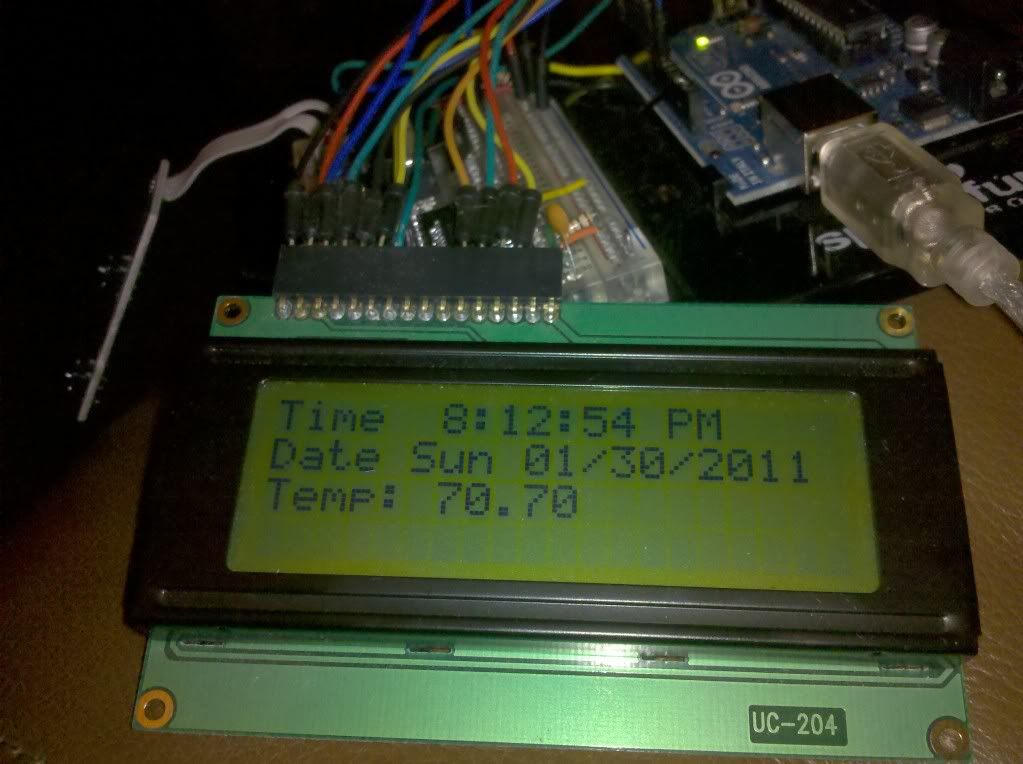
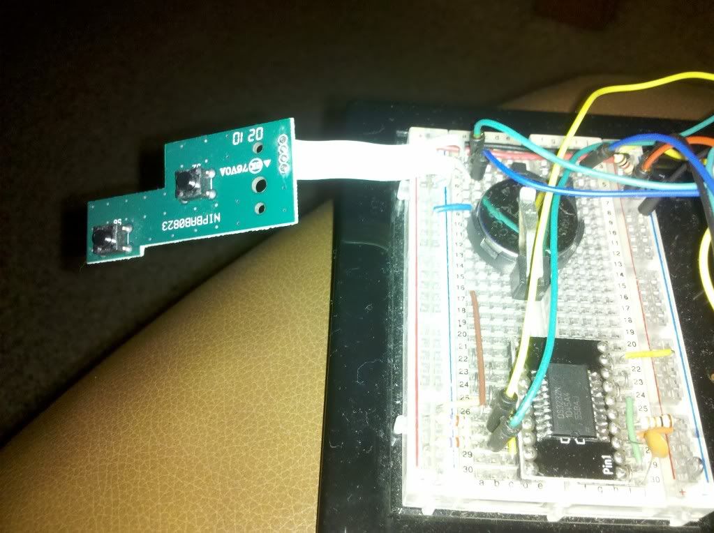
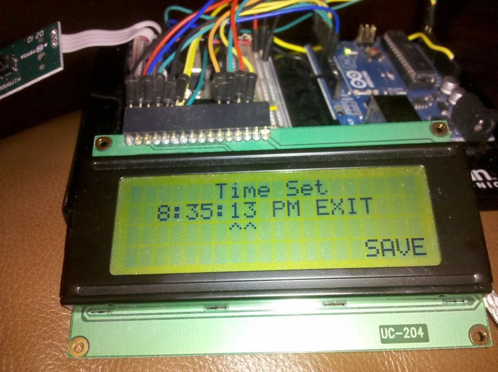
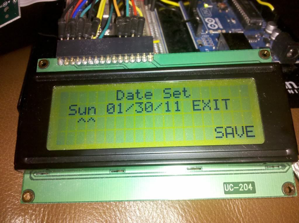
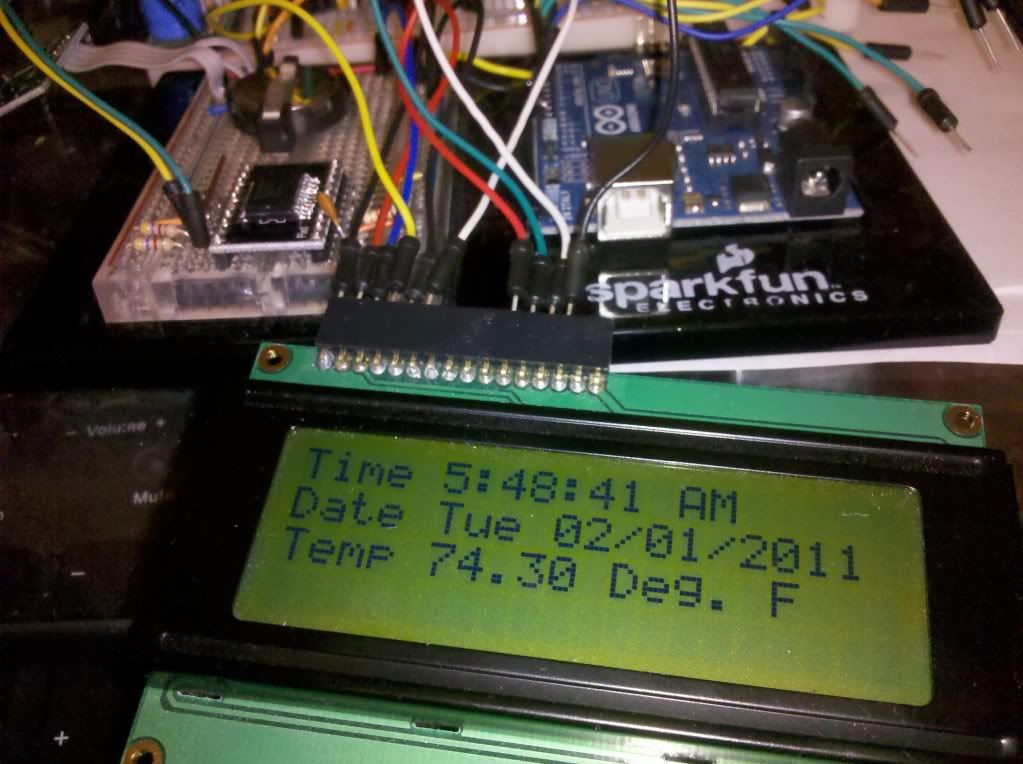
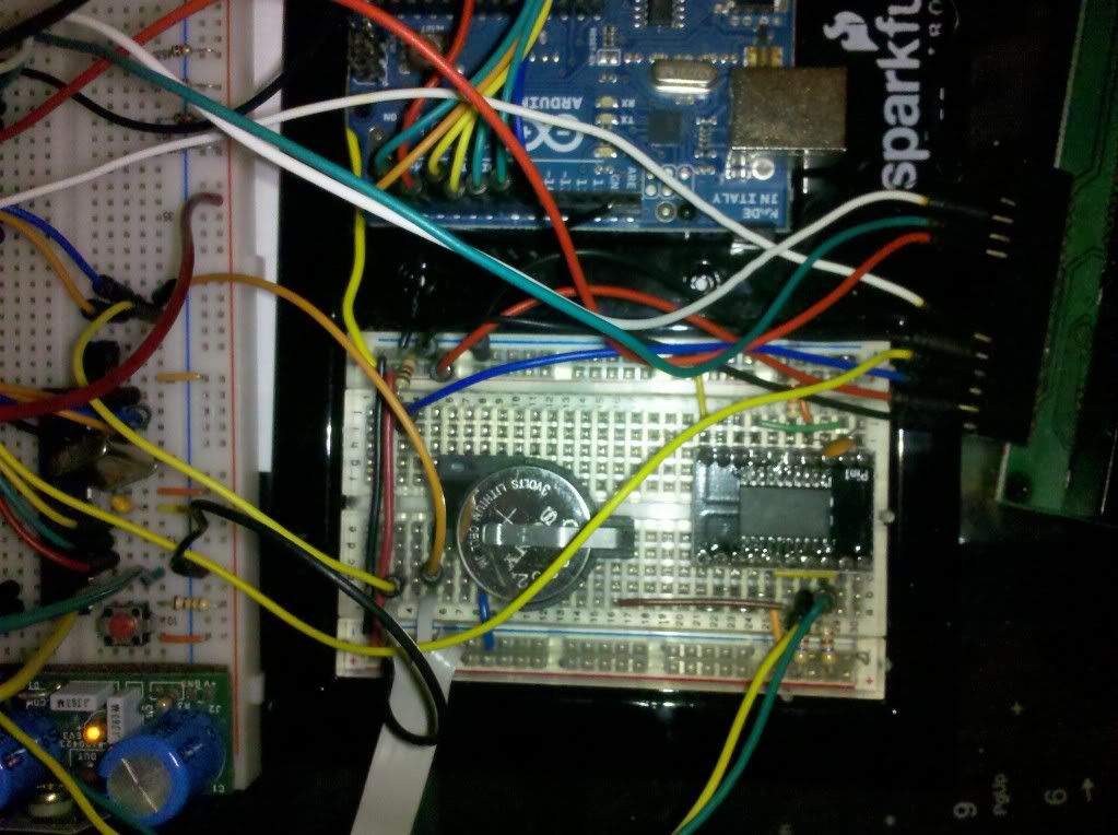
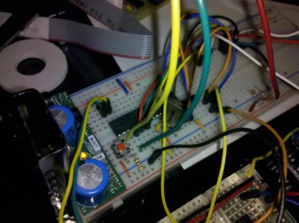
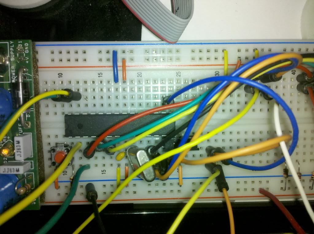
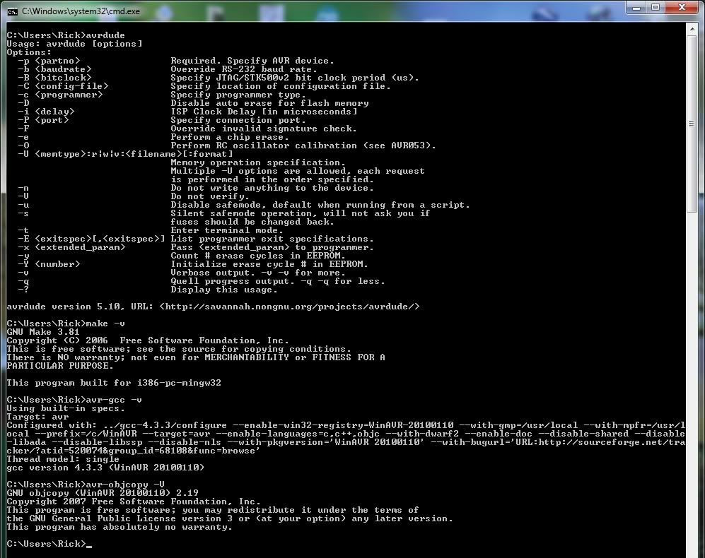


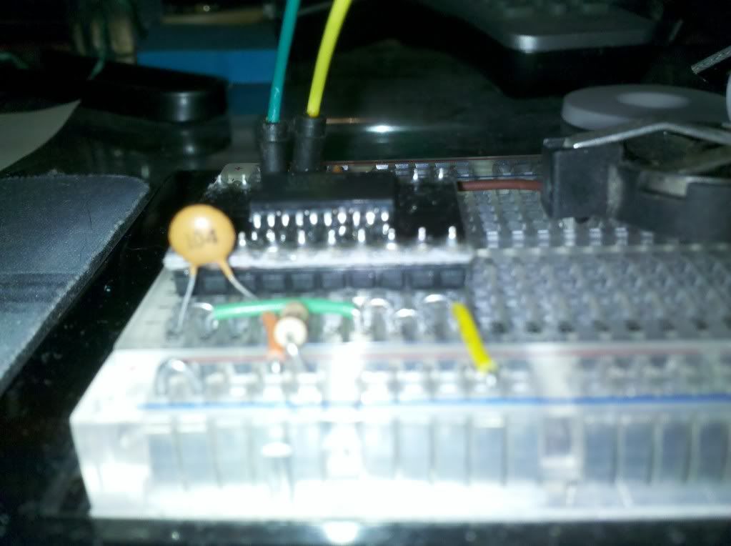
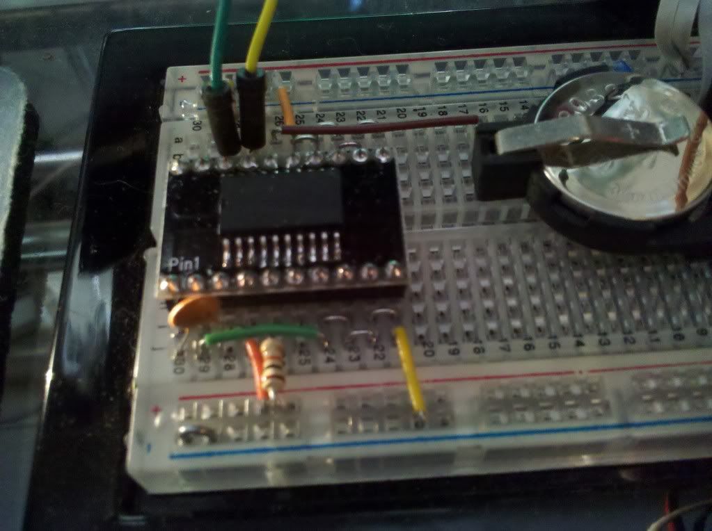
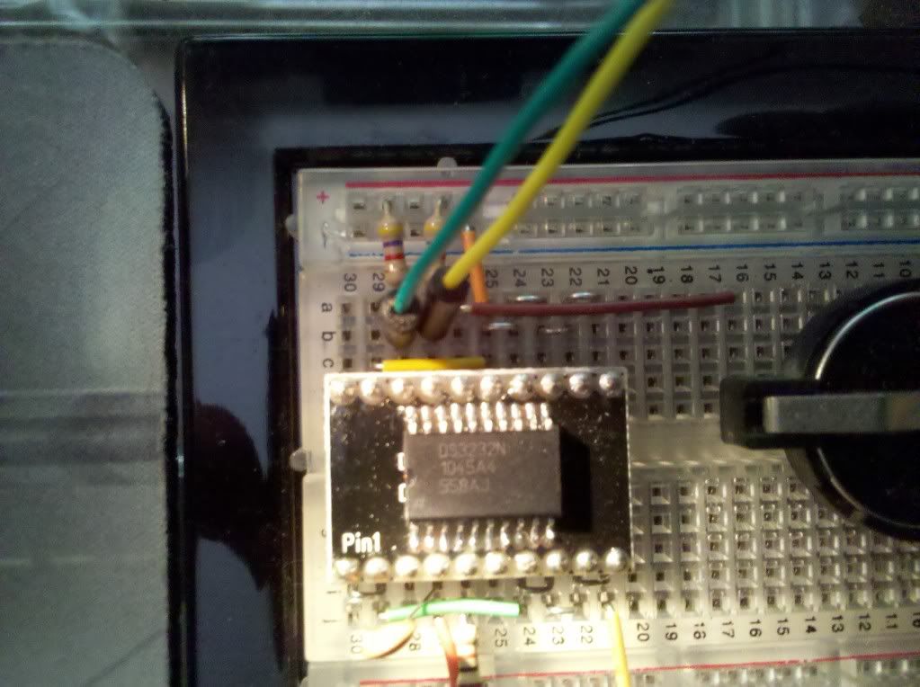
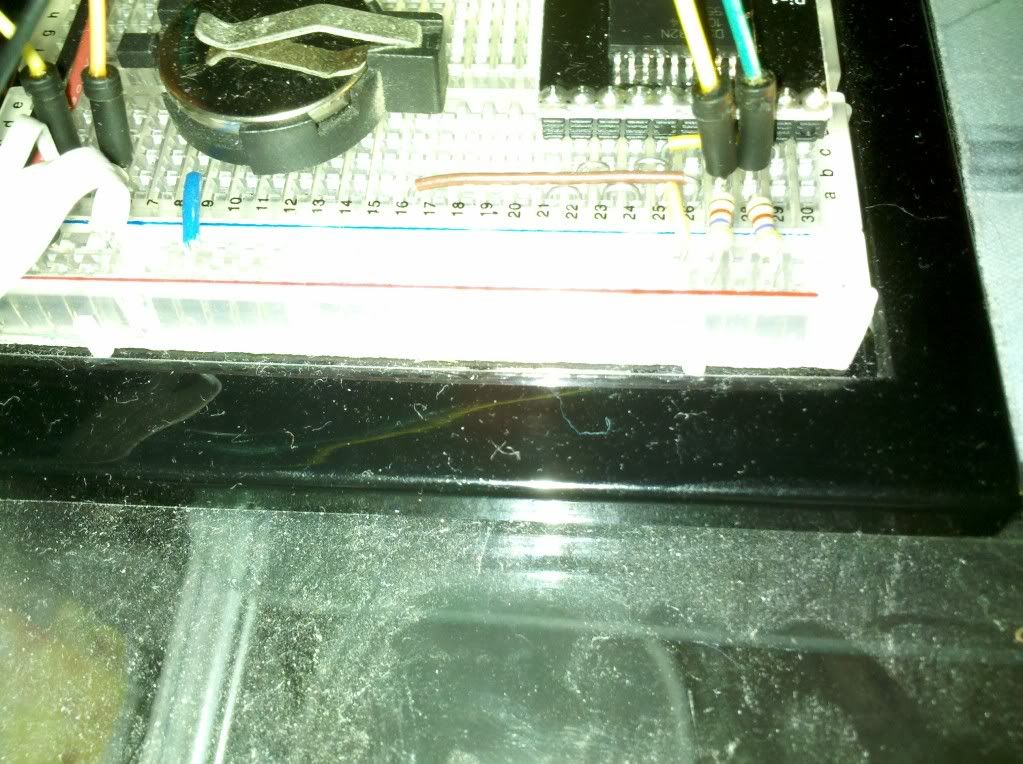
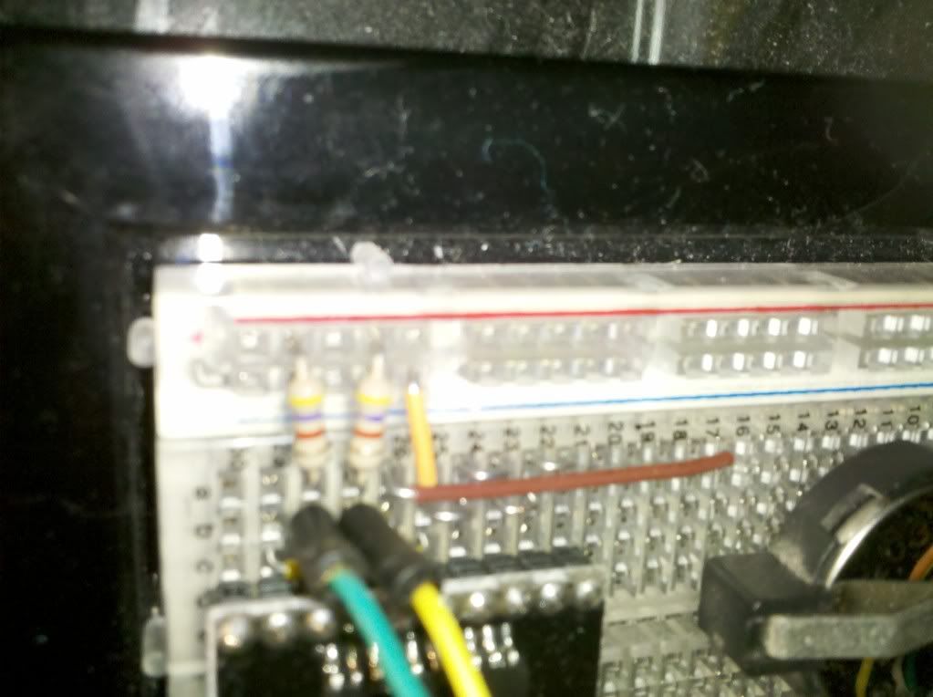

 1
1
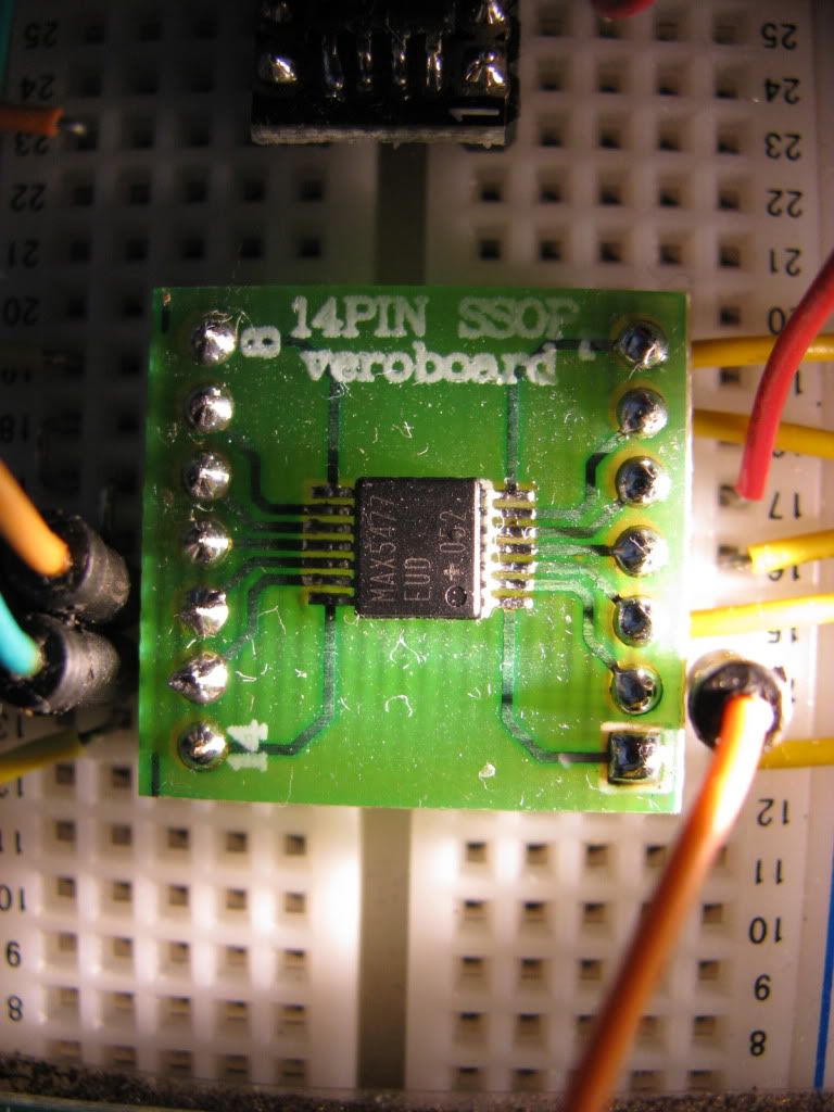

 How have you been? If you have any questions about the I2C LCD, let me know that's another of my "I wonder if I can do this" moments that acually panned out pretty good. Hope all is well with you and yours,
