NEW: Learning electronics? Ask your questions on the new Electronics Questions & Answers site hosted by CircuitLab.
Project Help and Ideas » I2C LCD progress
|
February 26, 2011 by Rick_S 
|
Just thought I'd post about my current project. Here's the goal: Build a backpack for the LCD display that contains hardware to allow full LCD display, backlight, and contrast control via the I2C bus. So only 4 wires (VCC, GND, SCL, SDA) would need to be connected to the micro-controller. So far I have I2C control of the backlight and display. Next step will be contrast control. Then the final step would be to design a circuit board to piggyback on the LCD. You can see the current results on Youtube. Let me know what you think. BTW, the I2C port expander and the I2C digital potentiometer are both Maxim devices a MAX7318, and DS1805. I plan to replace the DS1805 with the DS1803 dual pot so I can adjust the backlight brightness with one and the contrast with the other. Rick |
|---|---|
|
February 26, 2011 by mongo 
|
Where do you find the time for this stuff? I like that concept and adding the contrast just seems appropriate. (not really practical but a good exercise, as a small pot on the board does just fine for my use) I am interested in the I2C interfaces and that you are using 8 bit mode in the LCD. |
|
February 26, 2011 by Rick_S
|
I've been working on this off and on for a few weeks. The IC's were free samples compliments of Maxim. I added the tiny micro because the current output from the I2C pot is .1mA max. By using the micro, it's output is doing all the work plus I could do a PWM output to control the brightness. I have a problem with obsessive learning.... :D My driving force for this one was that I was getting tired of using up so many pins of the micro to drive the LCD. I have an email to Mike and Humberto to see if it's ok to post the code. My I2C lcd library is based on their library, heavily modified to make it 8bit with I2C output. If they give me the ok I'll post, otherwise, maybe I'll be able to email it to members who want it, since they would already have the standard library. Rick |
|
February 26, 2011 by Ralphxyz 
|
I want one, I want one. Ralph |
|
February 26, 2011 by Rick_S
|
You can have one... Once I get everything done, you know me, I always share. :) |
|
February 27, 2011 by Rick_S
|
Well, I've now connected the output of the digital pot to the contrast pin of the LCD and the contrast adjusts fine with it. So the next step will be to replace the single digital pot with a dual pot. That will allow me to adjust both backlight brightness and the contrast via software control. I was planning on going with a DS1803 dual 10k digital pot but may have to look for another digital pot though. I got to thinking, the DS1803 and DS1805 are volatile. So if the power goes out they both default to ground. That would mean you'd have to re-set the backlight and contrast every time it was powered up. I have three options.
Number 4 is obviously the easiest but not the most end user friendly. Number 3 would be the easiest from a programming perspective. Number 1 would be next best from a 'Use as little of the micro's resources as possible' standpoint. Number 3 would be the 'I already have the hardware and ability to use it' standpoint. I tried looking at maxim's site to see if I could find a viable replacement but they are all TSOP format and A) I don't have any adapters, B) Not sure of my soldering skills on that small a package, and C) Not sure if I could home etch a board with that fine of detail. Decisions, decisions.... Any input, anyone?? Rick |
|
February 27, 2011 by mongo
|
I'd go with #3. Soldering is really just a skill that refines over time. A good iron and a steady hand is really all you need. (make sure you use the right solder... A friend of mine used acid core solder and couldn't figure why his PC boards would fail after a while. He didn't know the acid stayed there and ate through them) |
|
February 27, 2011 by Rick_S
|
I've been soldering for a long time and am confident of my skills down to the .050 leg spacing on SOIC packages. I even figure I could home etch a board for them. But with TSOP, I'd be cutting the leg spacing in half as they're only .025" spacing. Not to mention how small the traces and spaces between would have to be for a home etched board. That's what really has me unsure. I guess I could buy some TSOP breakouts. Then worse case, I use them and etch thru holes for that device.... I think I've convinced myself... I'm going to order some... Thanks for talking me into it mongo!! :D Rick |
|
February 27, 2011 by Rick_S
|
Well guys, I've been given the OK to post the code. Before I do, let me preface that this is a work in progress. The LCD routines work fine, but I do plan to add more in the future. The LCD routines are VERY similar to those you are familiar with and can be used in your programs much the same way. The main difference from the outside looking in is that all the functions now have I2C_ as a prefix to thier names. For example: lcd_init(); would become I2C_lcd_init();. The librariy and supporting .h file should be placed in your program directory along with the hardware I2C library from Peter Fleury. (i2cmaster.h and twimaster.c). You should also edit your make file. Below I am posting the I2C_lcd.c and I2C_lcd.h library files, the test program I2C_LCD_TEST.c, and the makefile I use in programmers notepad. To build this project for just the LCD control, you will need a maxim MAX7318 16bit I2C port expander. For the contrast and brightness control, I was developing around a maxim DS1803. But that will change... that's why it isn't in the library yet :D So without further ado, here it is :D I2C_lcd.c I2C_LCD.h I2C_LCD_TEST.c And the Makefile If you try it out, let me know how it goes for you! Rick |
|
February 27, 2011 by Rick_S
|
Told you I'd share Ralph :D |
|
February 27, 2011 by Ralphxyz
|
Well in my spare time I'll just put it all together. But thanks so much Rick I really appreciate your sharing your projects and code. I know the general emphasis, here in the Nerdkits forum is learning, for people to learn by working things out with help from the community, if needed. Essentially making everybody start about two levels up from scratch. I on the other hand like to see published code of working projects, I am much better at taking "working" code apart and adapting it to my specific needs than writing code from scratch. In fact if I had to start from scratch and write my own code I would probable never do it. I am capable of writing my own code (in a limited fashion) but I have so many things I am trying to get done I just do not have the time. So I really appreciate yours and everyone else that publishes working code, now for those that publish their broken code and ask for and receive help, here in the forums, and then disappear never to be heard from again until they have another problem well I'll reserve my thanks for them. Ralph |
|
February 27, 2011 by Noter 
|
Very interesting ... I've been working on the same type of project to drive a display via i2c but have taken a little different approach. Instead of using a chip like the MAX7318, I am just using another atmega328. Getting the i2c master/slave protocol working between the two has been challenging but I finally have it going although still testing the heck out of it. I am running the master at 20mhz and the slave (display driver) on the 8mhz internal clock so I won't have to put a crystal on the piggyback. I've set the bit rate at the max for the slave (500khz) and have noticed I get a nak coming back from the slave when it has just finished processing a "busy" command. If I wait a ms between messages, the problem goes away but at 500khz a ms is a long time so I just let the error happen and restart that message and all is fine. Thanks for your post - I appreciate seeing a different method and will keep the MAX7318 in mind possibly for a future project. |
|
February 28, 2011 by Rick_S
|
I tossed the idea of using a micro like you. But, I didn't feel like figuring out the I2C slave stuff. I will admit though, while adding a second level of programming for the slave micro, it would drastically cut down on the hardware. I am learning a lot though playing around with the port expander and digital pots ;) Rick |
|
February 28, 2011 by Noter
|
It has taken a while to get the slave code working. Here it is if you want to give it a try at some point. I cut and pasted this from my test program that I think is working fine ... hopefully didn't miss anything. Eventually I will merge this code with the master routines and put it in a library so that is why I set the return or callback function with a pointer in the enable slave routine. |
|
February 28, 2011 by Ralphxyz
|
So Rick where did you get the blue LCD? Ralph |
|
February 28, 2011 by Rick_S
|
Bought it on ebay a couple of years ago. I've since harvested several LCD's from old electonics. Old HP printers and scanners are a great resource for re-purposed hardware. |
|
February 28, 2011 by BobaMosfet 
|
Rick, You can use an MCP4251 - dual, digital trimpot, SPI controllable (7/8-bit, and comes in a variety of max Ohm Ratings). This is what Malicious used in his submarine project. I reverse engineered the transmitter, redesigned his schematic, explained how the pots worked and more-- pretty much did all the heavy lifting he didn't know how to do. He disappeared. Last he told me is he'd filed for a provisional patent. Now, nothing. No word from him, nothing, so I don't know what happened with it. I don't know if he failed, gave up, was successful, or what. BM |
|
March 01, 2011 by Rick_S
|
I'm still in the research stage for the non-volatile digital pot. I'm really looking for an I2C device though. I have everything working on a breadboard, just need to replace the volatile pot with non-volatile so my contrast and backlight settings persist through power down/up cycles. I have to admit, I've pretty much been looking at Maxim devices but all their non-volatile pots are TSOP or smaller packaged. I may have to look at other vendors to see if they have a good solution in an SSOP or similar package. Thanks for the info though, Rick |
|
March 01, 2011 by Ralphxyz
|
Rick, couldn't you use the micros onboard EEPROM to store your settings? As long as you didn't change micros you would retain the settings and use your existing volatile digital pot. Ralph |
|
March 01, 2011 by Rick_S
|
I definately could, it would just be a cleaner standalone library if it didn't require eeprom storage on the micro driving it. Another option in the eeprom line would be to add an eeprom to the backpack board and store the settings on it. |
|
March 05, 2011 by esoderberg 
|
Noter, Please post your Master TWI code and Test code when you get it done. I've been trying to follow the TWI slave code posted above, but I'm not very fluent with pointers, so I'm not sure I understand all of it. I'd like to be able to play with the both Master and Slave sides to help figure out exactly how it's working. Eric |
|
March 05, 2011 by Noter
|
I'll be happy to Eric. I've hacked it apart at the moment to put into a library and apply a few final mods so it'll be a few days or maybe worst case next weekend. |
|
March 12, 2011 by esoderberg
|
Noter, If you get the chance, perhaps you could explain the flow in your program in a couple spots that have me confused. I think I understand what's going on in the TWI_init() and SIGNAL(TWI_vect) functions pretty well. What's still getting me is the function pointers, which I've now read up on, but have still not used much. I think I understand that the below code is calling the function TWI_enable_slave_mode, sending integer slave_addr and pointer address for another function(handle_TWI_result), as the arguments. But I don't get when function: is being called nor exactly what data is being put into its argument. Eric |
|
March 12, 2011 by Noter
|
Hi Eric, I haven't forgotten about you but I don't have my test program working well enough to post all of it yet. The TWI runs as expected and then pauses occasionally for about a second. I'm still working on figuring out what is going on when that happens. The handle_TWI_result() funciton is called from the interrupt routine by dereferencing the function pointer in the statement (*TWI_return_result)(TWI_status); and you can see that TWI_status is passed as a parameter. This isn't really necessary until the TWI code is compiled separately from the rest of the program and then the only way to tell the interrupt routine the address of the result function is by passing it a pointer to the function. I have made changes since posting that sniplet and hopefully I'll be able to post the working version with a complete test program very soon. Paul |
|
March 12, 2011 by esoderberg
|
Paul, Thanks for the quick note while you're still working out the kinks. I actually think I'm following your code all the way through at this point. Eric |
|
March 14, 2011 by Noter
|
Rick, I am having lots of problems with the TWI interface. I've finally figured out it is not software but rather the TWI wires have too much noise on them. I've switched pull-up resistor values, types of wire, shortened the wire as much as possible, extra caps on the power side, and reduced the TWI speed to below 10khz. Nothing is really solving the problem. My test runs fine until I wave my hand over the breadboard or get up from my chair or do just about anything and then I see errors that indicate the slave never received a data packet but with no errors on the master side. Are you having any issues with your TWI interface? Do you think there is may be just too much capacitance in the breadboard and that it may work fine in circuit? I appreciate any help you can give. Paul |
|
March 14, 2011 by esoderberg
|
Paul, I've been running TWI for comms between 328p and a wi nunchuck and motion plus gyro module, using code based on Peter Fleury's TWI library with inputs from Rick. I've run the TWI clk and signals through breadboards, multiplexer, and over wires of varying length with consistent good results at 330,000 khz. I had similar inconsistent results that you're seeing when I tried to use only the internal pull ups, vice 4.7k external pull ups on my current set up, but bottom line, seems to be that with the right code and pull ups, the comms seems pretty robust and insensitive to noise, even over a variety of circuits. There is one item I noted that you might want to check. In Fleury's code notes, he states that TWBR must be >10 for stable operation. From your snippet above, you're only at 3, and as your results sound unstable, that might be your issue. More on this at: http://www.avrfreaks.net/index.php?name=PNphpBB2&file=printview&t=79562&start=0 Eric |
|
March 14, 2011 by Rick_S
|
I have to agree with Eric. I've had my RTC clock project (FORUM LINK) running virtually non-stop on my desk since January. My I2C LCD has been running on my desk non-stop for a few weeks now with no interruptions other than what I've intentionally done myself. Both are running 400kHz, both just solderless breadboarded. You can see the squirrels nest of wires in the video link for the I2C LCD and Photo's in the forum link for the RTC. I can wave my hands all over both of those, even place fingers between the wires with no effect on the operation. (Maybe you're more electifying than me) :D I do agree though that it sounds like stray capacitance, being that a wave of the hand messes it up. Why it is sensative... I don't know. I really wish I did have more answers. I know of at least one other person who's had problems with I2C. If I were more knowledgable in it, I could possibly help both of you. Rick |
|
March 14, 2011 by Noter
|
Eric, Thanks for your help. I put TWBR above 10 and there was a little improvement but still many errors. Then I tried it with my usb cable unplugged from the PC and the errors really dropped off. I guess my PC has a lot of noise it's ground pin. I've reviewed my code and even went through Fleury's code looking for something but didn't find anything that made any difference on the remaining errors. I saw he waited for the STOP condition to complete before continuing so I did the same but saw no difference in results. I do like the way he calculates the value for TWBR so I adapted his method for that. I'll cleanup my code a little and post it for you. It's not overly complex or long and maybe you will see something I have missed. Or maybe it will run for you without error. Thanks again, Paul |
|
March 14, 2011 by Noter
|
Thanks Rick. I think I just noticed something that may be causing my problem. I have 8 leds displaying TWI status ongoing on both the master and slave. On the slave they blink so fast that many appear to be on all the time. I notice when I move my hand near the ones on the slave, I get lots of errors. But not when I have my hand near the leds on the master - the master leds don't blink unless there's errors. I often put leds on available pins to show some status when I don't have a display connected and not had an issue with them before but they do appear to be interferring with the TWI. Hmm ... I'll get back to you both after I rip'em out of there and test again. Paul |
|
March 14, 2011 by esoderberg
|
Paul, I can verify that at least the slave half of your code is OK because I have it running on a 328p with only a few small changes and communicating (read and write) with a master 328p running Fleury based code and it's working without a glitch as far as I can tell. All on breadboards as well. Eric |
|
March 14, 2011 by Noter
|
Well, I've been around the block on this again and still no solution on my side. I cleaned up the code to make it easier to see what is going on. One program, compile and load onto both targets with a jumper installed on the master. There is an image of the circuit in the master test directory. The only other code is in the lib directory and it's my current version of the TWI driver. I think I'll give it up for the day tomorrow and let my mind reset. http://www.datafilehost.com/download-4ef23e63.html for the zip file |
|
March 15, 2011 by Ralphxyz
|
Noter, how to you have the LEDs wired? "I have 8 leds displaying TWI status ongoing on both the master and slave." I am also having problems with TWI possible the leds might illustrate what is not going on. Ralph |
|
March 15, 2011 by Noter
|
Hi Ralph, if you download the zip file there is a .png image of the schematic in the TWI_master_1 directory. Take a look and see if that answers your question. |
|
March 15, 2011 by Noter
|
Probem solved !! The errors were caused by interference on the unused pins on the slave side. I tried to configure them as input with pull-up enabled but hit a snag with PB2. When I configured PB2 input w/pull-up, TWI slave interrupts stopped. Then I discovered that if I put a resistor PB2 to GND the interrupts would start again - wierd! That threw me for a while but then I realized PB2 is also SPI SS (chip select) so I started thinking there was a unwanted association between TWI and SPI. Next I pulled my spi programmer wires from the breadboard and tied all unused pins to ground with 1K resistors. It worked! No errors! Yahoo! I think there is a problem in the TWI slave module and thus I have submitted a tech support request to ATmel but in the mean time it appears all I have to do is allocate the SPI pins for GND on the slave. Whew, this has been a tough one. |
|
March 15, 2011 by Rick_S
|
Glad you got it. I don't have anything tied to my loose pins, but then, I'm not using TWI slave either :). It will be interesting to hear what Atmel reports back. |
|
March 15, 2011 by esoderberg
|
Paul, Great to hear your set up is working, although it's strange that PB2 would have any impact on the TWI comms; it doesn't on my setup using your original slave code. I've even tried running the scl/sda at 3.3v vice the normal 5v, and it has worked without fail. Thanks for posting your work, I've learned a good bit trying to follow it. I may try and write a Master only TWI program based on your code to match the Slave only TWI code I've got running, thanks to you, because the either master or slave code that you've written is still just above my head. Eric |
|
March 15, 2011 by Noter
|
Eric, You may be getting errors on your slave and not know it. I thought it was all working ok until I put the test program in place that actucally checked results beyond TWI return codes. The test master has the slave sum a few numbers sent in one or more separate transmissions and then gets the total back from the slave and checks it. That is where I was seeing errors, the number was wrong much of the time and it was caused by transmissions from the master that appeared to go ok but the slave never recieved them. I still got an error or two until I also put a resistor on PB0 ->> 5v. Now it has been running for a couple of hours completely error free. Thinking about it more, I wonder if it has more to do with PB0, PB2, as well as SPI because PB0 is SDA and PB2 is SCL on the ATtiny's. Maybe they have some circuitry design in common, maybe a little too much in common. It's beyond me to go further but as long as it works I won't mind putting in a resistor or two for stability. Also, I have removed the resistors from PC0 - PC3 and it's still working fine. I guess it is a little confusing having both the master and slave in the same program but it made it easier to change, load, and test so that's why I did it that way. Just concentrate on either the slave code or master code but not both when following the logic and it will make more sense. The slave code is just one TWI call to give the slave address and start interrupts and then the rest of the slave code runs in the handle_TWI_result function called by the interrupt routine. The master part is a little easier to follow because it all happens in main(). The only time the interrupt routine gets involved with the master is in the event of a TWI error. You'll notice a couple of the master errors are ignored because they happen frequently but are not fatal. Let me know if I can help. I've added a I2C serial eeprom that I'll try out tomorrow assuming my setup remains stable. Paul
|
|
March 15, 2011 by Ralphxyz
|
Oh boy this is going to be good thread. Thanks everyone so far I have already been learning so much. I have been trying to figure out how to get a external I2C EEPROM working. I needed to get a EEPROM so I figured bigger (biggest) was best so I have a ATMEL AT24C1024B-1meg EEPROM. I also have a Microchip 24AA128 EEPROM on order. I haven't the slightest (well now a foggy) idea how to do memory addressing to say nothing about getting the Master Slave communications working. So I am really going to be interested in seeing your code for the EEPROM. I am trying to get Rick's DS3232 RTC code working also. Ralph |
|
March 15, 2011 by esoderberg
|
Paul, Thanks for the extra comments on the code. As far as there being possible errors on the slave, not only are there no return codes generated, but in my test code I've got new data being generated every 1/10th second and it is accurately being transferred in both directions - I've got lcd's on both master and slave displaying data in/out on each. Eric |
|
March 15, 2011 by Noter
|
It sounds like you have it under control Eric. I wonder if I have some defective chips? I switched along the way to see if a different mcu would make a difference but they did all come from the same place and probably the same lot. I'm sure it is not my power source either because I switched over to a 12v battery yesterday just in case that was the source of trouble but it wasn't. I think I'll order a few new mcu's and see if they are different. Where's the best place to get them from? |
|
March 15, 2011 by Noter
|
Ok Ralph, you're in the right place today. ;-) I have a 24LC256 eeprom (a little one, 32k byte) and hopefully it will be easier to get it going than the struggle I went through with the I2C slave. I'll post the code as soon as it's working. |
|
March 15, 2011 by Ralphxyz
|
Noter, why not start a new thread instead of moving Rick's great thread further off subject. Ralph |
|
March 16, 2011 by Ralphxyz
|
Hey Rick, did you update your LCD display Youtube? Your original post is no longer working. I am trying to sample the portexpander and pot from Maxim as I really want this two wire LCD display. Ralph |
|
March 16, 2011 by Rick_S
|
The link is working for me... I haven't changed anything. Maybe it was a youtube thing... Please give it another try and see if it works. Anyone else have a problem viewing it or is it working now? Rick |
|
March 16, 2011 by Ralphxyz
|
Darn now Google Chrome is crapping out on me at least the Flash to play YouTube. It is so stupid one cannot update Flash until Chrome says it needs to be updated that is if you are in Chrome when you go to Adobe to attempt a update. I will have to try using Safari. The YouTube runs in Safari. Rick you sure have a good voice you could be a TV announcer or do commercials. Ralph |
|
March 16, 2011 by Rick_S
|
LOL, I think that would be an interesting career change. Glad you figured out why you couldn't view the video. Rick |
|
March 16, 2011 by Ralphxyz
|
well if I ever need a professional sounding speaker for a YouTube or other blurb I am going to hire you. Ralph |
|
March 19, 2011 by esoderberg
|
I have both interrupt based TWI master and slave sides working in separate code if anyone is interested. It is essentially Paul's work, but broken out between master and slave operations; as such there were some simplifications possible when only running one side of the TWI comms on a given chip. Referencing a classic old TWI/Wii Nunchuck thread largely from Rick - I've also got the code above being used to init and interface with the Nunchuck and Motion Plus module as well as sending and displaying the NC/MP data on a separate 328p via the same TWI. Using Paul's functions somewhat simplifies the rest of the coding versus that required using Fluery's lib for these operations as posted on the other thread. So far results are more robust as well with full 400khz NC/MP TWI transfers working; using the old code, transfer rates had to be in a window around 330khz or it wouldn't work - at least not on my setup. Eric |
|
March 19, 2011 by Ralphxyz
|
Eric, you know I am always interested. I like to see your interrupt based tWI code. Ralph |
|
March 19, 2011 by Noter
|
Eric, Great! I expect the separate versions compile to a smaller size too in case memory running low is ever an issue. I finished the original dual version and posted it on the "Access Serial EEPROM using I2C on the Nerdkit" thread. Made some changes that may interest you if you haven't seen it yet. The demo also uses only master mode vs the earlier test program where I had both master and slave combined in the code. Paul |
|
March 19, 2011 by esoderberg
|
TWIM.c TWIM.h |
|
March 19, 2011 by esoderberg
|
TWIS.c TWIS.h |
|
March 20, 2011 by Ralphxyz
|
It so wonderful having the "Indent Selection as Code Block" it really seems as if the volume and quality of code being posed in the threads has increased since that facility was added. Could you imagine having to push the space bar four times for every line like we used to do. I know you could use a text editor like Ultra Edit or NotePad++ and do vertical editing, to enter the space in one swoop and then cut and paste but selecting the text and pushing a button is so much easier and convenient. Thanks Eric and of course Rick and Noter and everybody else for really documenting with code how to use TWI (I2C). Ralph |
|
March 20, 2011 by Noter
|
It's easy to indent a code block with the programmers notepad. Select the lines (or all) you want to indent and then hit the tab key. The whole selected block moves over. To bring it back, hit backtab (shift+tab) while it is still selected. |
|
March 25, 2011 by Ralphxyz
|
Well Rick I went to Maxim and got some "sample" 7318 Port Expanders and the DS1803 Addressable Dual Digital Potentiometers. Do you have a schematic? I sure will like having a two wire LCD. Of course that means more work for me. I got some blue LCD off ebay, I can barely read them. Did you find that you had to use the backlight to see your blue LCDs? Ralph |
|
March 26, 2011 by Ralphxyz
|
Rick did you get a static digital potentiometer in place of the maxim DS1803? I am really close to putting this together, both the LCD I2C and the Master/Slave I2C fascinating. Ralph |
|
March 26, 2011 by Rick_S
|
I did order samples of the MAX5477. They are tiny TSSOP packaged 14 pin chips. I did finally get some breakout boards for them and soldered one up. It went much better than I anticipated. Then I went on vacation. Just got back last night and haven't messed with coding up the new chip yet. The Max5477 is a non-volatile dual 10k pot. Programming for it will be a bit different in that it uses an eeprom for the non-volatile pot position storage. It also has a live register that you can change while leaving the settings in the eeprom alone. The thought would be the user would change the settings to what they like, then either leave them for the current run or save them to eeprom as a new power on default. As for the Blue LCD's, the backlight is required to be on. They do not work passive like the green one in the NK kit. Keep in mind, there is one other part to the circuit in the LCD-back pack I've been working on. That is the attiny85 programmed with PWM output into the 2N7000 MosFET that varies based on the input from the digital pot. This is what I was using to power the backlight on the LCD. I may get time to mess with this tomorrow, if not hopefully this week sometime. Rick |
|
March 26, 2011 by Ralphxyz
|
Instead of the attiny85 (I do not have one) why not use I2C digital potentiometer a transistor to turn the backlight on or off? What is the PWM doing? Or if variable voltage is desired for the backlight why not use a digital potentiometer. I like the Mater/Slave I2C concept but am not sure what it is doing for the LCD backlight. |
|
March 26, 2011 by Rick_S
|
The I2C pot would provide a 0 to 5v but only at .01ma Due to it's low current output, I sent it's output to the tiny85 which would in turn provide a PWM output into a 2N7000 mosfet that changes the LED backlight brightness. The PWM changes the Duty Cycle rather than adjusting the voltage. The other pot will directly adjust the contrast input on the LCD. I haven't messed with the I2C Slave code, but honestly that could eliminate almost every chip on the I2C backpack. Mainly because having a full size micro on the board as a slave, it could control the LCD and it's brightness. The only external chip would be a single non-volatile digital pot for the contrast control. I'm so deep into my method though, that I probably won't go that way... at least not for now. :) |
|
March 26, 2011 by Ralphxyz
|
Man this is all so interesting, thank you so much for your time and willingness to share your projects. And thanks for the quality of your projects, you really have put a lot of thought into them. Of course I know you are learning as you go also. Ralph |
|
March 26, 2011 by Noter
|
Hi Rick, I just want to follow up on the I2C problem I was having with errors. It turned out to be a bug in my test program (I'm so dumb sometimes) and once corrected everything works fine without errors. Another thing I want to tell you is that I'm quite impressed with ATmel's level of support. When I opened a problem report with them I wasn't sure if I'd really ever hear from them or not but they responded in a couple of days and stuck with me through resolution. That sure makes me feel good about them and their products. Paul |
|
March 27, 2011 by Rick_S
|
Ralph, I put together a basic schematic for the I2C LCD w/o the digital pot circuit. This circuit will allow the LCD to be controlled but has provisions for manual contrast and constant backlight.
Hope it helps. It's really just a visual of the comments in the top of the library. Rick |
|
March 27, 2011 by Ralphxyz
|
That's great Rick, thank you. Now I have to get Eagle going to make up some break out boards. I have a number of devices that I want to prototype using a breadboard like the MAX7318. I was thinking of drawing up ten different breakout boards and having them manufactured instead of my trying to etch them myself. I have seen breakout boards from $8.00 to $19.00 which is outrageous. I have to learn to use Eagle of course. It seems that doing breakout boards in Eagle would be a good place to start, but i have tried to learn Eagle at least three times in the past year and have not gotten very far. Ralph |
|
March 27, 2011 by esoderberg
|
Ralph, There's a good tutorial on Eagle at: http://www.sparkfun.com/tutorials/108 It took me a few hours to work through the tutorials but I can now produce schematics and gerber files in relatively short order. Eric |
|
March 28, 2011 by Ralphxyz
|
Thanks Eric, I know there are a number of tutorials, I even have a book, but I just have not been able to grasp it. I will especially when it gets to the point of using Eagle or paying for breakout boards to say noting of making actual circuit boards which I will eventually (soon) need to do so I'll be following your link. I can rationalise buying breakout boards for expediting learning purposes for only so long. Thanks Ralph |
|
April 05, 2011 by Ralphxyz
|
Rick what does the I/0 notation designate on your schematic? Another thought: Have you thought about using the unused pins for Input? Using pin1 for initiating a Interrupt you could have 5 buttons working, or so a example I found on the web says. Of course the I/O designation prompted that thought. Talk about saving pins I definitely have to figure out how I2C input works. Ralph |
|
April 05, 2011 by Rick_S
|
Input/Output (I/O) Yes, there is no reason I know of that the 5 unused I/O's could not be used for Inputs. The inputs can be set to trigger an output pulse on the INT pin that can be tied to the microcontroller to trigger an event. The inputs can then be polled to see which are set. Another option would be to use one of the outputs to toggle the backlight by driving it via a 2N7000 mosfet. Rick |
|
April 05, 2011 by Ralphxyz
|
Sorry I meant what is the I/O listing there for? Is it applicable to the schematic or just to functionality. Ralph |
|
April 05, 2011 by Rick_S
|
It designates which pin of the port expander goes to which pin on the LCD. |
|
April 06, 2011 by Ralphxyz
|
Darn I get so intimidated with anything new or different designations. I was worried that I had to do something because of that I/O labeling. Thanks for your patience. I'll explain this whole thing in case anyone coming behind us might have the same question or similar problem. I really do not know what my problem was except I just was not looking a your schematic logically. I/O15 is a label for the functionality of Pin20 which goes to Pin14 of the LCD. Just as SDA is a label for the functionality of Pin23 which goes to Pin27 of the mcu. I knew pins 4 through 20 of the Port Expander were I/O pins but something just didn't click when I started assembling the circuit from the schematic and it threw me. Geesch some people. Ralph |
|
April 06, 2011 by Rick_S
|
No problem Ralph, we all have those moments. :D |
|
April 06, 2011 by Ralphxyz
|
It is so interesting that now that I have so much time on my hands that I am really getting to know parts of my character that I had never known existed or that I was always to busy to pay any attention to. Especially since all of this electronics and processor stuff is still so new to me, I have often "looked" at schematics through the course of different jobs I have had BUT I have never looked at a schematic with the purpose of actually building the circuit. It definitely, for me at least, forced a different mind set on me and I found it intimidating. Well one (of many) new thing learned today so I am progressing. Ralph |
|
April 11, 2011 by Ralphxyz
|
Ok Rick, I just finished the LCD backpack protoboard. I will build your code tomorrow and try it out.
That switch is a five way switch to use the Port Expander input functions. I was going to chop the protoboard off to fit under the LCD but then thought what the heck I'll use the space for some permanent components like the I2C RTC and I2C EEPROM so there are two i2c buss on the protoboard to add components later Anything special I need to do or watch out for? Ralph |
|
April 11, 2011 by Rick_S
|
Not that I can think of... I'm jealous, I haven't built mine in permanent form yet. I did try a non-volatile digital pot for the contrast and backlight, however, the pot I used provided no way to read back what it is set at. So I think I'm just going to drop those functions altogether and just build the basic circuit I drew in the schematic. I'm eager to see it work for you! Rick |
|
April 12, 2011 by Ralphxyz
|
Sorry to ask this during working hours, you can answer me after work. In your I2C_LCD_TEST.c code you have a button and the DS1803 being called, can I just comment this out? You do not have the button or DS1803 on/in the schematic. Or is there some needed functionality. I have the LCD contrast wired thru a potentiometer and hard wired 33Ω resistor for the backlight. I hope I can just replace any LCD calls with I2C_LCD... in all of my programs. Ralph |
|
April 12, 2011 by Rick_S
|
You should be able to comment any of the DS1803 code out. For that matter, you don't even need to use my base program. The library as written will work as a replacement for the NK library by placing the I2C_lcd.c and I2C_lcd.h files in the libnerdkits folder, changing the references to lcd.o and lcd.c to I2C_lcd.o and I2C_lcd.c, adding to the makefile to create an object file for twimaster.c, and use a different include at the top of the program (I2C_lcd.h instead of lcd.h) If you have trouble, I'll throw a simple makefile together when I get home for you. Otherwise, the code is the same as it always was with the NK lcd library. Rick |
|
April 12, 2011 by Ralphxyz
|
Thanks, that is what I was thinking but had to make sure. I would like to make a libRick folder to go with the libNoter and libnerdkits folders. Ralph |
|
April 12, 2011 by Ralphxyz
|
Darn, now I have the hard part to do. There is apparently some sort of short on my protoboard as the voltage regulator gets hot (scorching hot) immediately after turning on power. My multi-meter says it is open between + and - so it will not be a obvious dead short I am looking for. This condition is without any of the components (LCD and I2C Port Expander) in place. I removed the ground side from the potentiometer as that was showing 1k Ω between + and -. With open between + and - I do not really know what I should be looking for. The scorching hot voltage regulator is usually caused by a dead short but that will show up on the multi-meter. Any suggestions are welcome. Ralph |
|
April 12, 2011 by Rick_S
|
Accidentally wire it backward? |
|
April 12, 2011 by SpaceGhost |
How much voltage are you putting into the regulator? |
|
April 12, 2011 by Ralphxyz
|
Wiring it backwards is what I thought, but there is nothing connecting anything together so that should not matter. SpaceGhost what would input voltage to the regulator have to do with this problem? Wow this is strange, I have a two wire power plug wired to the two center rails of the protobard. I left test pins on the rails and between the + and - test pins on the protoboard it is open. Now if I plug my power jack in and test between the two wires on the power jack there is a closed short but the short does not appear on the protoboard test pins, the power plug wires are somehow isolated from the protoboard. I have the power jack encased in some liquid tape so I can not readily see the connection wiring. I'll replace the power jack and see what happens. Very strange but typical for me, I always seems to get these stupid things happening. I removed the power jack (destroying it in the process) and replaced it with another. Now the LCD lights but I am not getting any readout. I am using the original code without modifications so I'll look at that. But hey it lights up and the regulator doesn't heat up so I must be on the right path. This is where having a debugger would really help. But I do have my new digital analyzer and oscilloscope to "help" diagnose the problem, now if I just knew how to use them. Ralph |
|
April 13, 2011 by SpaceGhost |
Well, it's been my experience that higher voltages into the regulator = a warmer regulator... My regs usually run cooler @ 9v as opposed to 12v. I was just curious, that's all. This may not be contributing to your problem, but I didn't know. |
|
April 13, 2011 by Rick_S
|
The regulator had to be connected to your power to get hot. If you accidentally plugged in your power connector backward (Plus to minus, and minus to plus) the regulator would heat up quickly. Regardless, it sounds as though you have power now. I'll put together a somewhat standard NK makefile, with a version of the initialload program to demo it for you when I get home tonight. That way you can test it out without having to comment/delete any code for pieces you don't have. Rick |
|
April 13, 2011 by Rick_S
|
Ralph, As promised, Here is a version of the initialload program renamed to I2C_lcd_test.c and a basic NK style makefile. To use this, place my I2C_lcd.c, I2C_lcd.h, Peter Fleurys i2cmaster.h, and twimaster.c files in the libnerdkits folder. Then place the Two following files in a folder within the code folder. The makefile should then be able to compile the files without error. I2C_lcd_test.c Makefile Rick |
|
April 13, 2011 by Ralphxyz
|
Rick I get the same empty lcd with the new code like I was getting with the original code. Now this might be most likely worthless information but I looked at the I2C bus with my new Digital Analyser and this is what I see:
Now I do not know what I am doing with the analyzer so do not put to much weight in the image but all I am seeing is the button bounce when I turn the circuit on and then a straight line high SDA and SCL. I will compare with the I2C RTC and EEPROM to make sure I am connecting correctly. If I get a reasonable wave with the RTC and EEPROM installed on the breadboard I'll install them on the protoboard to make sure my circuit is correct. In fact I can move the port expander to the breadboard easily as I used sockets and headers on it so it is not soldered in place. Ralph |
|
April 14, 2011 by Rick_S
|
I loaded the code on my breadboarded setup prior to posting it, so I know it is working. I just double checked my port expander wiring in the schematic I drew to the setup on by breadboard and it matches pin for pin. I'm not sure what is happening, maybe trying some of the other devices like you said to narrow it down. Rick |
|
April 14, 2011 by Ralphxyz
|
Thanks Rick, I of course knew your schematic and code were correct. Of course this was my first reflow soldering experience so I might have toasted the IC! I'll test it on my breadboard which I know the I2C buss is working properly on. Ralph |
|
April 14, 2011 by Rick_S
|
Any luck yet Ralph?? |
|
April 14, 2011 by Rick_S
|
Ralph, what kind of logic analyzer do you have? I've been thinking of one and was just getting ideas. |
|
April 14, 2011 by Ralphxyz
|
Whoooo Whew!!!
Hot Dawg it works!! Thanks so much Rick, wow that frees up Port D, now more trouble I can get into. I wonder how much I can ask of the mcu before it starts complaining. re Digital Analyzer: I have a IKALOGIC Scanalogic2. I cost me $99.00 from Saelig plus $9.89 shipping. IKALOGIC has the analyzer in kit form but you have to do two sided smd soldering which might be a challenge. I do not see the kit on Saelig's website. The IKALOGIC developer is all most finished with a new major software update, he is very responsive on their forum and always looking for feedback. I have not yet gotten the analyzer to show me dependable waveforms but it is starting to work, now I need to understand what I am seeing. The Scanlogic2 will also function as a signal generator so I can use it to teach myself how to use my oscilloscope also. So thanks again, I'll have to see why my protoboard failed to work but at least I know my reflow soldering was successfull which I was questioning. Ralph |
|
April 14, 2011 by Rick_S
|
Sweet!! It's nice to see that on someone else's LCD!! Glad it worked out this time. Rick |
|
April 15, 2011 by Ralphxyz
|
Darn turned it off last night and now this morning I am getting a blank LCD. Ralph |
|
April 15, 2011 by Ralphxyz
|
Well I rebuilt the circuit on my breadboard and it is working again, I still can not get the protoboard to work. It is using the Nerdkit LCD to work on the protoboard if I try to use the blue LCD from the protoboard on the breadboard it fails to work so possible there is a issue with the blue LCD (which does work on the breadboard using the Nerdkit LCD library). Geesch, detail details details. Ralph |
|
April 15, 2011 by Rick_S
|
You scared me there for a moment Ralph... Hopefully your blue LCD is ok, If you had your power backward when your regulator heated up, it may have gotten hurt... Maybe try it in a basic config to see if it still works with the standard NK setup. That would at least narrow it down. Rick |
|
April 15, 2011 by Ralphxyz
|
Yes the blue LCD works using the default Nerdkits LCD.h. If I strip the breadboard and redo everything it worked until I turned the mcu off. When I turned the mcu back on all I got was the blank lcd (green or blue). In fact now I am getting the two black bars on the green lcd in run mode. There just has to be something, but what? Ralph |
|
April 15, 2011 by Rick_S
|
I thought I hadn't tried my NK LCD with the project, but I just hooked it up to it and it works fine as well. I hope you figure out where your problem lies. Rick |
|
April 15, 2011 by Ralphxyz
|
It's upsetting to not be able to turn the mcu on/off and to have it work I can understand that I might have a glitch on my protoboard but you'd think that if it works once on the breadboard it ought to work the next time. I was going to makeup a new protoboard but not being able to have it work on the breadboard has me worried. I sure am glad I did not make up a PCB. I'll get it to work, it will just take a while to sort everything through. It works for you so it has to work for me. Ralph |
|
April 15, 2011 by Noter
|
Maybe the cat walked on it during the night? |
|
April 15, 2011 by Noter
|
Just kidding! I did have that happen once and now I remember it was because I left out the base resistors on a couple of transistors. They got hot and everything still worked but the next morning after things cooled off the transistors didn't work anymore. I thought that was kind of strange but put in a couple of new transistors with resistors and all was well. Notice any or your components getting too warm when it was last working? |
|
April 15, 2011 by BobaMosfet
|
Ralph, If your LCD is blank or has black bars, perhaps it's power-related? BM |
|
April 16, 2011 by Ralphxyz
|
This is embarrassing, I have been nagging the developer for the Digital Analyzer complaining that the digital analyzer was failing to read a I2C signal. I replaced the not working I2C LCD module with the I2C Real Time Clock and ta dah everything works. I have been trying to fix two problems when in actuality there is just one problem, my implementation of the I2C LCD program. This program "had" worked in the past and does work for Rick so there has to be something that I am doing to make it fail as demonstrated by the blank or two black line lcd display and by the digital analyzer failing to capture a waveform. Oh the digital analyzer was failing to trigger on a rising edge so it never got started. I am going to have to put this project on the back burner as this whole LCD thing was just a side track from getting my "real" projects working, the weather station and the water curtain. I do not "need" the I2C LCD for either of those projects. I had really just wanted to free up PortD so that I could use it for more input pins which I do not believe I will need. We see how long I can let this simmer on the back burner. Ralph |
|
April 18, 2011 by Ralphxyz
|
I know I am not supposed to be looking at this, but but I added the headers for the I2C RTC module to the protoboard just to see if it would work, which it does, so I know my I2C bus is correct and not the problem with the I2C LCD not working. So the I2C RTC works from the protoboard, this saves space on the breadboard. As the RTC will be a permanent fixture, I'll be able to leave it on the protoboard while setting up new circuits on the breadboard (rationalization #234). Now the digital analyzer not getting initialized means there is something "not" happening with the i2c_init() or with the I2C_lcd_init(). It would seem it must be the i2c_init() failing, if that was working (getting initialized) wouldn't I at least get a SCL (clock) signal. It appears from looking at the working I2C RTC signal that the SCL is not a continuous signal but only appears when the master prompts it. Is that correct? So how would I narrow this down to see what is working (getting initialized) and which isn't? If the SCL was a continuous signal I could see that it was initiated at the start. It sure would be nice to have a on chip debugger maybe I can see something in the AVRstudio simulator debug environment. Well any suggestions would certainly be welcome. Ralph |
|
April 18, 2011 by Noter
|
If the SCL buss is staying high, it is idle waiting for the master to start a transmission. If it's low, could be a transmission has started and likely the slave is holding it low for some reason. Or if it is low before a transmission starts, it is considered busy and the master will never start. The datasheet has all the detail on signal states. So, if your lines are low, either it started and got stuck or never started because of missing pullup's or something else holding the buss low. Could be the pins on the slave are configured output instead of input. If the lines are high, then the master has not tried to send anything and maybe the init is not running. Or it sent the data and is finished, waiting for something else to send. |
|
April 18, 2011 by Ralphxyz
|
What would cause the undefined references? Here is the code: The code is just the tempsensor project modified for the Atmega328p and then attempting to use the I2C_LCD code. I tried to use the regular LCD code to run simultaneously but the compiler didn't like that so I thought I'd just try the I2C code. The I2C LCD modifications are based on Rick's initialload I2C code. Thanks, Ralph |
|
April 18, 2011 by Rick_S
|
Try not to include lcd.h as well as I2C_lcd.h... I'm not sure if it will go away with that or not, but it may. |
|
April 18, 2011 by Rick_S
|
Don't forget, you'll have to modify your makefile as well so that the correct libraries are compiled. |
|
April 18, 2011 by Rick_S
|
This what you're after??
And the Makefile |
|
April 18, 2011 by Ralphxyz
|
Thanks Rick. I was on the path to the changes to the Makefile, which I had forgot initially. With your changes I still get the same error I was getting: Ralph |
|
April 18, 2011 by Ralphxyz
|
I am going out of town for a couple of days so I probable will not have any further progress until Friday. Ralph |
|
April 19, 2011 by Rick_S
|
Ok Ralph, Hope all is well and your time away is for a vacation. Hear from you soon, Rick P.S. Did you miss a line when changing your Makefile? Your error would normally indicate that the text following all: isn't seen as a section in your Makefile. |
|
April 22, 2011 by Rick_S
|
Ralph, I know you just got back, but I was wondering if you ever tried this out again.. Rick |
|
April 22, 2011 by Ralphxyz
|
Drats, I used the above tempsensor code and Makefile but I still get a blank LCD. It compiles fine. I am seeing a waveform on my Digital Analyzer and on my oscilloscope, but I am not getting anything on the LCD. Any ideas of where to even start looking? Or what to look for? This is using my protoboard I can re-setup the breadboard but the last time I was getting the same blank LCD. Could/Should I monitor pins on the port expander directly, what pin would I monitor and what should I see? Ralph |
|
April 22, 2011 by Noter
|
Can you post a pic of the signals from your analyzer? |
|
April 22, 2011 by Ralphxyz
|
Here is a AVI capture of a session. It is a huge file so once it starts to download just go do something else for 10 -15 minutes. Then the first 2 - 3 minutes I am setting it up so you can fast forward once it is fully downloaded. I also monitored pins 19 and 20 on the MAX7318 and they were flat line never a blip. Would there be a difference with the TSSOP package than what Rick used? It is acting like the MAX7318 is not getting initiated although there are Acknowledgements. I can do closer screen shots if thee is any thing that might want to be examined closer. I have some sectioned decoded with highlights and others just the raw signal. Ralph |
|
April 22, 2011 by Ralphxyz
|
Here is static screen shots of the Start (Decoded and not Decoded):
Around 96us shouldn't there be a Acknowledgement blip? Ralph |
|
April 22, 2011 by Noter
|
Glad you got the pics, the movie download wasn't working for me and I killed it after 40 minutes. The ack is there. The data line would go high during the ack/nak clock pulse if it was a nak. Take a look at the specification, page 217 - 21.3.3 ... When a Slave recognizes that it is being addressed, it should acknowledge by pulling SDA low in the ninth SCL (ACK) cycle. I see the start at about 72us, can you change your sample rate and show more than one byte on the display. Try to get everything between the start and the next stop. Although, since the device address was ack'ed it appears I2C is working. We are looking at a a start write command (SLA-W) for device address 0x20 (010 0000 W). Is that what you expect? |
|
April 22, 2011 by Ralphxyz
|
[quote]We are looking at a a start write command (SLA-W) for device address 0x20 (010 0000 W). Is that what you expect?[/quote] Hey Rick is that what was expected? I am still leaning how to use the Digital Analyzer I'll see if I can compress it. Ralph |
|
April 22, 2011 by Noter
|
I looked at the code above, way above, and yes, that is what is expected. Here's the assignment: and It's clearer to think of it as (0x20 << 1)+(I2C_WRITE) and you can see the 0x20. Anyway, see if you can get all the bytes between the start and stop and let's make sure there are no nak's and the slave is releasing SDA in a timely fashion. Otherwise it appears I2C is working and something else is the problem. |
|
April 22, 2011 by Rick_S
|
Man, I've got to get one of those logic analysers. That is slick! |
|
April 22, 2011 by Noter
|
They really are the ticket. I don't think I would have ever be able to get my TWI master/slave code working without one. If I were looking to buy one now I'd probably get one like Ralph's and save $150. I think it would be fine for anything I'd want to do. |
|
April 22, 2011 by Rick_S
|
I know that one is only $79 at one US online retailer. I'm kinda torn between it and the one sparkfun sells. I don't know if I would need the extra four inputs or not but I do like the look of the sparkfun unit and it's software. But it is $150 too. |
|
April 22, 2011 by Noter
|
Heck, you only live once - might as well have some fun! Or should I say Sparkfun! That is a neat looking little unit. |
|
April 23, 2011 by Rick_S
|
That's the way I was leaning... I've been passing hints at the wife. My birtday is mid May and with fathers day only a month after that... Maybe I could talk the family into it. If not, I'm going to have to start trying to save up for it. I can easily see how one of those would go a long way toward troubleshooting serial communication issues. Rick |
|
April 23, 2011 by Rick_S
|
BTW, I meant my birthday is mid May not birtday. |
|
April 23, 2011 by Ralphxyz
|
Rick, ikalogic also makes a do-it yourself kit Scanlogic2 Digital adapter. Now that would be fun. I think the four probes will last me a long time before I need a device with more. Ralph |
|
April 23, 2011 by Ralphxyz
|
Oh, one other thing about the Scanlogic2, if post a question on their forum within a couple of hours (or even faster) you will have a reply directly from the developer. Ralph |
|
April 23, 2011 by Ralphxyz
|
Here is a whole scan sequence:
I actually figured out how to compress and expand the view, using the magnifying glass Duh. Now I am trying to reconcile what I am getting with the specsheet: How would I see Register1 and 2 on the Analyzer?
It's neat I can show a 7 bit address or 8 bit address, that should help me understand the device addressing as I still have not fully wrapped my head around that. I do not understand where the decode values are coming from I would expect a sequence of high/low blips |||00||| (blipping meaning a low high low transition). |
|
April 23, 2011 by Noter
|
Hey Ralph, That's good. No NAK's, your i2c looks good. I don't know what you mean about register1 and 2. What you see on the analyzer is the datastream between the master and slave. For a better understanding now would be a good time to dive into Ricks code and see what is being sent. It looks to me like his MAX7318_write function sends SLA-W followed by 2 bytes (address and data) then a stop and that seems to match what is showing on your analyzer. So I think i2c is working fine for you. What else could be preventing your display from working? Maybe a crossed wire on the display? Maybe the display is damaged/broken? Maybe a bad resistor on the contrast? VCC connected? Good ground? |
|
April 23, 2011 by Ralphxyz
|
First thing how are they getting the blip on Data Out Port 1. What pin would I use to see Data Out. I believe Data Out is coming from register 1 and register 2. I am trying to see if anything is being output. I put the other two probes on pin 19 and 20 and I saw one of the pins go high in the middle of a session and stay there for the rest of the session. I am interchanging the LCD's so I know they are good, I use them with the Nerdkit LCD library then switch to the I2C_LCD routine. I have rung out the protoboard and all of the wiring appears to be good. The back light is lighting on the LCD. When I look at the SDL and SDA signals using my oscilloscope the signals are inverted which surprised me. The signal certainly looks good coming from the analyzer but thought I'd mention that fact. I remember the trouble I had geting Rick's DS3232 RTC code to run was caused by faulty wiring so I have been especially careful with the protoboard wiring. Also if I setup on the breadboard I get the same results, the blank LCD. Maybe I'll switch back to using the breadboard until I get this running, that way I can closer imitate Rick's working setup. Why me, I always get in these situations where things that ought to just work don't. Of course all of these struggles enhance my learning experience but I sure would like to see something just work for once. blah, I am getting discouraged besides this is not what I am supposed to be working on. I still have questions about the EEPROM and I still have not started working on my I2C Magnetic Sensor Module or my I2C Barometric Pressure sensor. At least my Relative Humidity sensor will just use the Nerdkit tempsensor code using the ADC so all I need to do for that is to figure out how to use a lookup table. I'll probable use the internal EEPROM for that look up table as I actually have a good handle on using it thanks to Dean Camera's excellant tutorial over on AVRfreaks. Sorry I am really getting frustrated and get carrying on with with all of my moans and groans. I am looking at Rick's code and the output from the analyzer and it actually looks good to me also. Ralph |
|
April 23, 2011 by Noter
|
If you suspect the MAX7318 you could make a small test program using Rick's code as a base and send only one command/data to the MAX7318 to set some pins and then check them with your volt meter. Then maybe send a different command/data and check those results and so on until you're sure the MAX7318 is doing what it is supposed to. Or put an infinite loop in his code after writing the 1st command so it will stick there and not change anything while you check the pin states on the MAX7318. SCL and SDA signals are not inverted when I look at them with an oscilloscope so some setting in your oscilloscope must be causing that. |
|
April 25, 2011 by Ralphxyz
|
Ok since I got Inino's Port Expander working I wired up the LEDs to use Port2 which Rick uses and as suggested by the guys on the digital analyzer forum tried the port expander with the LEDs using Rick's tempsensor code! All 8 of the LEDs blink!! Some are brighter than others but all eight are flashing! So what now? It was suggested that possible the problem was the contrast resistor. I had had a 10k potentiometer but now have a hard wired 10kΩ resistor. Rick what are you using for the contrast resistor? I had tried mounting the LCD on the breadboard instead of the protoboard but had gotten the same results, a blank LCD. I'll set it up again on the breadboard. At least now I know the port expander is working. making progress!! Ralph |
|
April 25, 2011 by Rick_S
|
I have a 10k pot too. Did you verify both ports working?? My I2C_LCD code uses the first 3 bits of the first port and all 8 of the second port. (currently it only toggles the enable line) I connected all three in case I wanted to get daring and try reading from the LCD. |
|
April 25, 2011 by Ralphxyz
|
After the blinking LEDs on Port2 mounted a green LCD on the breadboard and ta dah it works!! I do not know what is different, I fixed the solder joint on pin 11 but that pin is floating now so it should not have made any difference. Well now I'll find my splice piece and try the blue LCD and then I'll try my protoboard again. Now that's exciting. Thanks again Rick for putting this together, and of course thanks for the help and support from Paul. I want to use the I2C LCD for all of my projects. Ralph |
|
April 25, 2011 by Ralphxyz
|
Drats, I still get a blank LCD on the protoboard, Darn. At least I know it is not I2C, the port expander or the breakout board that is causing the problem. With the breadboard working I "should/could" pull wires until I simulate what is happening on the protoboard and that might point me to a fix. I could not find my splice piece to test the blue lcd but I might have a way to test the blue LCD on the breadboard. Both the blue and green LCD fail on the protoboard. Ralph |
|
April 25, 2011 by Ralphxyz
|
I rebuilt the breadboard and now I can just barely read the green LCD. Does that imply needing a high or lower resistance for the contrast resistor? Possible the whole problem is with the contrast resistors. HELP Ralph |
|
April 25, 2011 by Rick_S
|
I think lower. I know my pot is almost at the end of it's travel. Good thing though, if you can read it, that means it is working. Rick |
|
April 25, 2011 by Ralphxyz
|
Yeah it works (barely) using the breadboard but not on my protoboard. The length of the wires also seem to effect it. When I first got it to work I used three inch wires and the display was pretty good. Now with six inch wires it is barely readable. Does that make any sense? I'll try putting a pot on so that I have adjustment. Ralph |
|
April 25, 2011 by Rick_S
|
Were you so excited you had to say that twice? I wouldn't think an extra 3" of wire would effect anything... But, it wouldn't hurt to put a pot on the contrast line that way you have full control. Rick |
|
April 28, 2011 by Rick_S
|
Ralph, did you ever get around to this?? Just curious if you ever got it going. Rick |
|
April 29, 2011 by Ralphxyz
|
I started working on this March 26th here it is April 29th a month later and I can finally say IT IS WORKING!! Persistance has always been my greatest asset and my greatest determent. I just do not know how to stop once something gets my interest. IT IS WORKING!! I2C LCD is actually working on my protoboard.
You would not believe what I have gone through to see this working. In fact I need help understanding why it works!! Remember my "problem" was a blank LCD. The backlight would light but nothing would appear on the LCD. This was using Rick's I2C LCD code. Besides working on this I also worked on Inino's most helpful thread on multiple buttons I got Inino's I2C io_expander code to run lighting the leds on Port1 now this was using my breadboard. So I switched the leds to Port2 and the leds all lit! So this proved the problem was not caused by my first attempt at SMD TSSOP soldering, the I2C Port Expander worked. Then I loaded Rick's I2C LCD Tempsensor code which he put together up above with a Makefile. The tempsensor I2C LCD code ran on the breadboard with some of the leds still in place. Next I removed all of the leds and the tempsensor still ran. Whenever I tried to use my protoboard instead of the breadboard all I got was the blank LCD. I had tried to put this on a back burner and to work on something that I actually needed like my I2C Barometric Pressure sensor or my I2C Magnetic sensor Module. I actually started working on the DS3232 Alarm function but totally screwed that up so I had to start over with a bunch of things. So today I "thought" (DANGER DANGER!!) since using the leds on the io-expander project seemed to get things working on the breadboard why not add the leds to the protoboard and see what happens. The protoboard was not designed for adding the leds so it sorta looks slopped together (which it is) but ta dah!!
IT WORKS!! Having the leds lit enables the LCD to work. WHY? (that ought to be a good one for mongo or BobbaMosfet) Of course any contribution (guesses) will be appreciated. I have not dared to remove the leds to see if it is just circumstance that it is working today. I suppose the leds might be functioning as pull-down resistors on the LCD data lines. I might be able to replace the leds with resistors of equivalent values. How would I measure the resistance of a led? IT WORKS!! I can do away with all of those wires on the breadboard plus I get the added pins of PortD on the mcu. Thanks Rick for publishing your projects and ongoing support, and of course thanks to everyone who has contributed to my understanding of I2C and microprocessors in general. Ralph |
|
April 29, 2011 by Ralphxyz
|
Well I removed the leds, and it still works. It stills seems as if the leds pulled the port expander into action but hey it works. Moving on!! Ralph |
|
April 29, 2011 by mongo
|
Yep, the LED's are probably acting as loads. Measuring them for resistance is not all the straightforward. Figure they pull 20 mA with a current limiting resistor on a 5V supply. 20 mA on 5V is about 250 Ohms, including the resistor and LED in series. It probably is lower than the total you have here so I would suggest maybe 470 Ohms to 1K to get started with. |
|
April 29, 2011 by Rick_S
|
Well, Here's to hoping it continues working! One down, now on to the alarm setting of your real time clock. Did you see my post over there Ralph? Rick |
|
April 29, 2011 by Ralphxyz
|
Thanks mongo and Rick, well it is working now without the leds, I might not need to do anything. Yeah Rick good points on the alarm. I really do not need the alarm per se, it would be nice, but what I really need to understand is I2C device registers and I2C prompted interrupts so I thought the alarms handled that. I need to finish Inino's io_expander code for I2C Input (multiple switches). That will involve reading a I2C register and I2C interrupts. I have a five-way switch on my protoboard wired to Port1 on the port expander so all need is to work out the code. Whowee, one month later moving on!! Oh, I shut the circuit off for a hour and it worked when I re-energised the circuit so hopefully it is dependable. Ralph |
|
May 05, 2011 by Ralphxyz
|
Hi Rick will you publish a link to the .scl(? schematic) file for the I2C_LCD project. Your amended schematic. Now that I have the protoboard working I would like to make the backpack a PCB that would really clean things up. I have Eagle and really need to learn how to make PCB's so this would be a great place to start. Ralph |
|
May 05, 2011 by Rick_S
|
Sure, you can get it Here. I included the .sch schematic file as well as a .brd PCB layout. Board layout isn't verified, so use it at your own risk. It is layed out for the SOIC format chip. If you want to play with making your own layout, just load the sch file without copying the brd file. It will then make a ratsnest of parts that you can place yourself and route. Rick |
|
May 05, 2011 by Ralphxyz
|
Thanks Rick, fun fun fun I've gotta learn learn this stuff. Ralph |
|
May 05, 2011 by Rick_S
|
No problem |
|
June 06, 2011 by n3ueaEMTP 
|
Rick, All is well here. I havent had much time to devote to much of anything other than work and Cub Scouts. I've taken over a leadership role at my son's Cub Scouts and that is taking more time than I realized. I hope all is well with you as well. I do have two questions about the I2C LCD if you don't mind.
Thanks in advance. Chris B. |
|
June 06, 2011 by Ralphxyz
|
I just picked up a refurbed Lexmark E322 laser printer for $27.00. The sale might have ended. I really want to try making my own PCBs. I figured for $27.00, if it works along with a discontinued PCB kit from Radio Shack (on sale) I will get dangerous on the cheap. I'll try printing Rick's circuit and Noter has a circuit I want on a PCB also. Ralph |
|
June 06, 2011 by Rick_S
|
No Chris, there would be other files needed for a board house to make the board. Also, I haven't built the board myself and just built those files quickly. So I'm not 100% sure on the placement of the parts working out ok or not. As for the address, I'm at lunch at work right now so I can't look at the datasheet, but there are a bunch of addresses available to that chip and some did use some methods I haven't seen before. I didn't mess with those and just used the AD0,AD1, and AD2 lines. Rick |
|
June 06, 2011 by Ralphxyz
|
Yes Chris, I believe that is how you would set other addresses. Ralph |
|
June 06, 2011 by Rick_S
|
Yep, connecting the address lines to one of those three sets the address. I just connected them to ground in my project. Rick |
|
June 06, 2011 by n3ueaEMTP
|
Thanks Rick & Ralph. That's what I thought but wanted to make sure. Rick, I may just take the plunge and send the files off to try it out. Sparkfun.com has a board house that I'm sure has been mentioned here in the past BatchPCB that makes boards relatively cheap. I’ll let you know how it goes. Thanks again guys Chris |
|
June 06, 2011 by Rick_S
|
Chris, I wouldn't bother sending those files. I know for a fact there are more files needed than what I put in that zip. There needs to be several different gerber files for the top layer, bottom layer, silkscreen, drill layout etc... None of those are in the zip. I just put together a basic board layout for anyone who wanted to try to home etch. I have had one board done by BATCHPCB (Sparkfun's board house) for a project for work, and those were the files needed. Now if you were to load up eagle, you could use the files in that zip to create the production files. There are lot's of instructions on the web for doing that. Just remember if you do, that the layout is untested, non-checked, and use at your own risk. Rick |
|
June 10, 2011 by n3ueaEMTP
|
Rick & Ralph (and anyone else interested in this project), I found that Futurlec (sp) make boards pretty inexpensively and I can use the Pad2Pad software. To that end, I’ve whipped up a quick backpack that can be made for $3.26/each in a quantity of 10. As a comparasion, I paid $3.95/each for a SOIC-28 breakout board. If we order a second time, the cost will be much less. Anyway, I’m going to order a batch of 10 if anybody wants one. It’s just the bare bones backpack, the 7318 and 20 holes for wires or pins (16 for the LCD and 4 for power & the I2C wires). Let me know your thoughts. |
|
June 11, 2011 by Rick_S
|
Hey, if it works out, put me in for one. You have my email, just send me a message where to paypal the board cost to. Do you have an image of what the board routing looks like? Is it two layer? Rick |
|
June 21, 2011 by n3ueaEMTP
|
All: My breakout boards finally arrived for the MAX7318. Soldered the first one and it didn't work. I spent an hour messing with the code to get it to work and then I thought that maybe it was a soldering issue. Tried soldering again and viola! The LCD works like a charm on the I2C port!! Nice work Rick!! PS: I ordered the backpack that Rick and I came up with for the LCD, who knows when it will get here. |
|
June 21, 2011 by Rick_S
|
At first I thought you were going to say you ordered the boards and they were here... Got my hopes up I'm glad you got it working... it makes for an easy way to free up a bunch of pins when using an LCD. I'm looking forward to the custom boards. Rick |
|
June 21, 2011 by Rick_S
|
Chris, What's the meaning behind your QR code avatar? Doesn't appear to have anything to do with amateur radio or EMT-Paramedics... Some secret??? |
|
June 21, 2011 by n3ueaEMTP
|
Rick, I ordered 10 backpacks to start with. We'll see how it goes. The QR code avatar is supposed to take you to my website but it may have expired. I do have a question: I tried to add the LED backlight via a MOSFET to I/O7 (pin11) on the MAX7318 but it doesn't seem to work. What I basicly did was copy a line from the I2C_lcd.c file. Is this incorrect? Thanks Chris B. |
|
June 22, 2011 by Rick_S
|
For testing purposes, you would have to turn on bit 7 not 1 so it would be or Whichever you prefer. Keep in mind, this will not work when using the LCD as that would turn off all the other bits that are used for the LCD output. To make it work integrated with my library will take a bit of re-writing so the RS, RW, and E lines don't effect the backlight and vice versa. Rick |
|
June 22, 2011 by n3ueaEMTP
|
Rick, I did try turning on bits 1 and 7, neither worked. I also tried Both with no success; would I need to do (1<<8) etc throughout the I2C_lcd.c program as well? I did change a few of the lines in I2C_lcd.c to (1<<n) where n is the bit that needed changed and the lcd still worked but that may be because it didn’t re-compile the I2C_lcd.c file. There is a place for the MOSFET on the backpack so I’d like to get that working if anybody else wants one. Thanks again. Chris. |
|
June 22, 2011 by Rick_S
|
It won't work in the I2C_LCD library as written because every write routine will turn it off again and any direct write to that port will mess with the control lines of the lcd. Just to check you are getting something at the expander though, you could tie an LED with current limiting resistor directly to the output you are trying to toggle to see if it works. |
|
July 12, 2011 by Ralphxyz
|
Well I am trying to reload the I2C-LCD project but it ain't working!! Here is what I am getting with my Data Analyzer: I am getting the same results for the LCD test program and for the temp sensor program. I believe the problem is the No Ack. So what does that suggest? Is there something wrong on the backpack? The backpack is a soldered up protoboard not a breadboard. This has worked in the past. Thanks for the help and any suggestions on how to proceed. Ralph |
|
July 12, 2011 by Rick_S
|
I'm not really sure what's going on Ralph, but the slave address for the 7318 as I wired it would have been 0x40 not 0x20 as your seeing. That would explain why you aren't getting an Ack from the port expander. It will only reply if the address matches. Rick |
|
July 12, 2011 by Rick_S
|
Although, looking at the signal it looks more like 0x40 than 0x20 even though the text shows it that way??? |
|
July 12, 2011 by Noter
|
It's showing the address as 0x20 correctly because the low order bit is the read/write indicator so the address bits are all shifted left by 1 position in the SLA-W byte. |
|
July 12, 2011 by Rick_S
|
Yes, Noter, I understand how that software is interpreting the address as if it were shifted 1 bit. But that doesn't change the fact that the address shown by his analyser should be what the chip is expecting. If you read the datasheet for the 7318, it doesn't use the nomenclature of many if not most I2C data sheets in that it calls out the slave address of 0x40 being 0100000.
Even though I know 0100000 is really 0x20 and doesn't become 0x40 until shifted. Thus the analyser reporting 0x20. So why he isn't getting a response from the port expander... again, I'm not sure. Rick |
|
July 12, 2011 by Noter
|
Hmm, I wonder why Maxim did that? I can see how that could lead to some confusion over the addres since the analyzer is reporting the it according to the I2C standard nomenclature but the Maxim doc is different. Actually after looking at the spec, I think it is an error in the document. The description of the address is normal as well as figure 6 (the 1st image you posted) and then is says to reference table 7 for slave addresses but there is no table 7 ... I would cross out that column and pencil in the correct address values as needed. Then it would match the analyzer and the rest of the world. |
|
July 12, 2011 by Ralphxyz
|
I believe the 0x20 is coming from a setting in the Data Analyzer. I'll confirm this tomorrow. Here is how it is defined: Ralph |
|
July 12, 2011 by Noter
|
What are the SCL and SDA references as related to slave addresses in table 6? Does it mean connect the SCL/SDA line to the address pin? |
|
July 12, 2011 by Noter
|
That's the correct value Ralph. Must be something else going on. Double check your pull-up resistors and SCL SDA connections although seems they must be correct too if the data analyzer is showing signal. Basically a NAK means the slave is not responding or not connected. The NAK is the default signal provided by the pull-up resistor and it's required for the slave to pull it to GND for an ACK. Check the power and GND to the slave too. |
|
July 12, 2011 by Rick_S
|
Yep, to get additional addresses, you tie the ADx lines to GND, VCC, SDA, or SCL. Gives a lot of different address possibilities. As for Ralphs issue, I too am guessing there has to be something going on hardware wise... Hard to say what though. Rick |
|
July 13, 2011 by Ralphxyz
|
The 0x20 was coming from a setting on the Data analyzer:
So the slave is not acknowledging I wonder what might have changed. I have not changed the protoboard it has just been sitting on my desk, not connected. I wish it was a address issue, that would be easy to fix. Darn now I am getting a "Error in stream synchronisation" with just the mcu connected. I can no longer connect to the mcu to get a Data Analyzer reading. I even swapped out the mcu but get the same error. Ralph |
|
August 08, 2011 by isdale |
Aloha - Have you seen the AdaFruit i2c / SPI character LCD backpack ? It looks like a $10 turnkey solution for what you have been doing. Unfortunately their board doesnt label pins and the schematic (EagleCAD etc) seem to use different assignments than what I see in the NerdKit booklet. Jerry |
|
April 01, 2012 by Ralphxyz
|
Hey Rick, I am "trying" to use your I2C_LCD library in a new project. Here are my compiler errors: So "undefined reference" means a path problem right? Here are my #includes taken directly from the I2C_LCD test.c file: I have my PING folder in the same root folder as the I2C_LCD folder, which works!! Thanks, Ralph |
|
April 01, 2012 by Ralphxyz
|
Here is my main section of the code that gets the errors: Interesting that Line 91 I2C_lcd_stream is not tagged! Ralph |
|
April 01, 2012 by Ralphxyz
|
Duh, I missed one minor detail, the Makefile!! I used the one from the I2C_LCD test, modified for my file name and surprise surprise it compiled!! Now to get the code to actually work. Ralph |
|
April 02, 2012 by Rick_S
|
Sorry didn't get to you yesterday, wife had me busy away from the computer. Glad you got it worked out though. Rick |
|
April 02, 2012 by Ralphxyz
|
Working great!! Of course the first project I am trying used PC4 so I had to change the code but so far it doesn't work so I must have missed something. Ralph |
Please log in to post a reply.
|
Did you know that you can build a digital read out (DRO) for a lathe or milling machine? Learn more...
|


Copyright © 2013 by NerdKits, L.L.C.

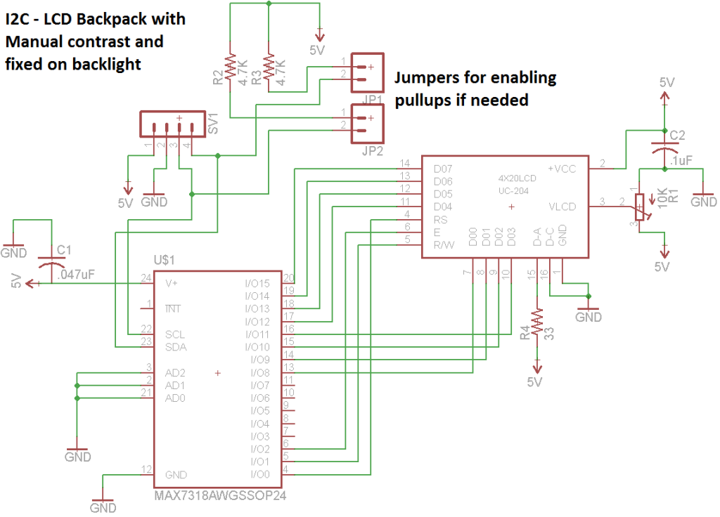


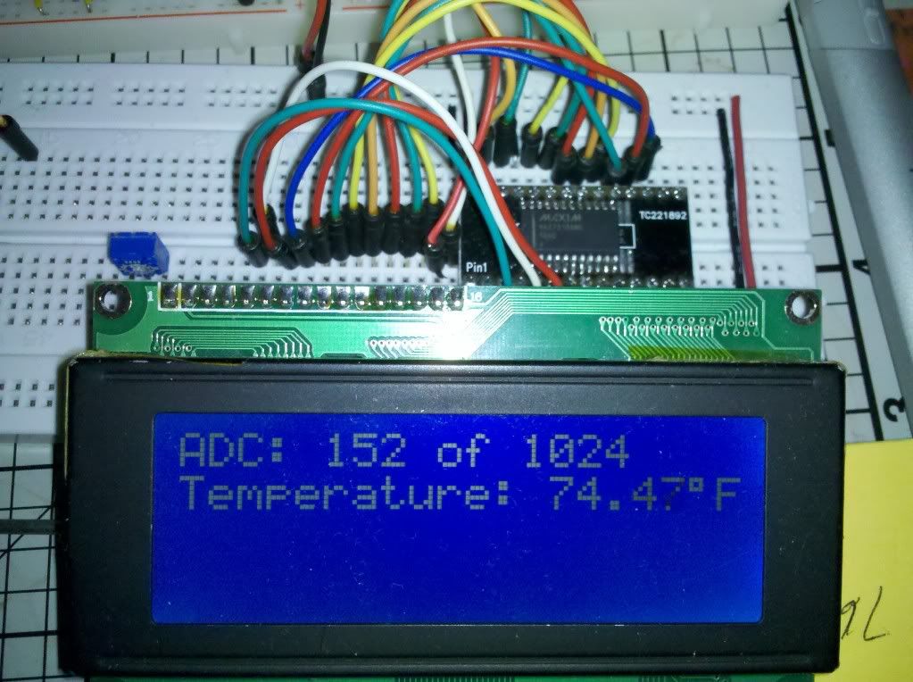


 Hopefully they'll work out. I'm pretty sure we checked them over thoroughly enough. When they get there, e-mail me and let me know how much they are. If you bought the 10 pcs you were talking of, I'll probably buy two from you if it's ok.


 .
.