Motors and Microcontrollers 101

Electric motors are a key way of converting electrical power (voltage and current) into mechanical power (torque and speed), and because electric motors are simple and reliable machines, they can be found all over, in many different shapes and sizes. Just considering a normal (gasoline-powered) car, there are a great number of electric motors:
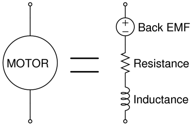
And I'm sure you can think of others. But from an electronics perspective, motors are slightly tricky loads to control -- they're not just a resistor! Even for a single applied voltage, their current varies with loading, starting, and stopping, and the energy stored in the magnetic field of the windings means that they are inductive, which can present a danger to other circuit components if it isn't handled properly.
While a full analysis would have to look simultaneously at the motor and the attached mechanical system, in this video tutorial we're just going to address the electrical side of the system. This includes some experiments you should try with a DC motor, a model of the system from an electrical perspective, building a MOSFET-based switching circuit, and finally two demos of a microcontroller-operated motor. This video and webpage specifically addresses a brushed DC motor, and although the specifics are not fully applicable to brushless (BLDC) motors, stepper motors, or AC motors, the big ideas about motor modeling and control will be useful in those areas as well.
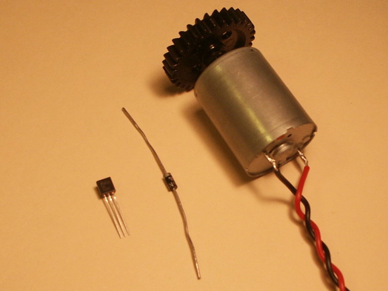
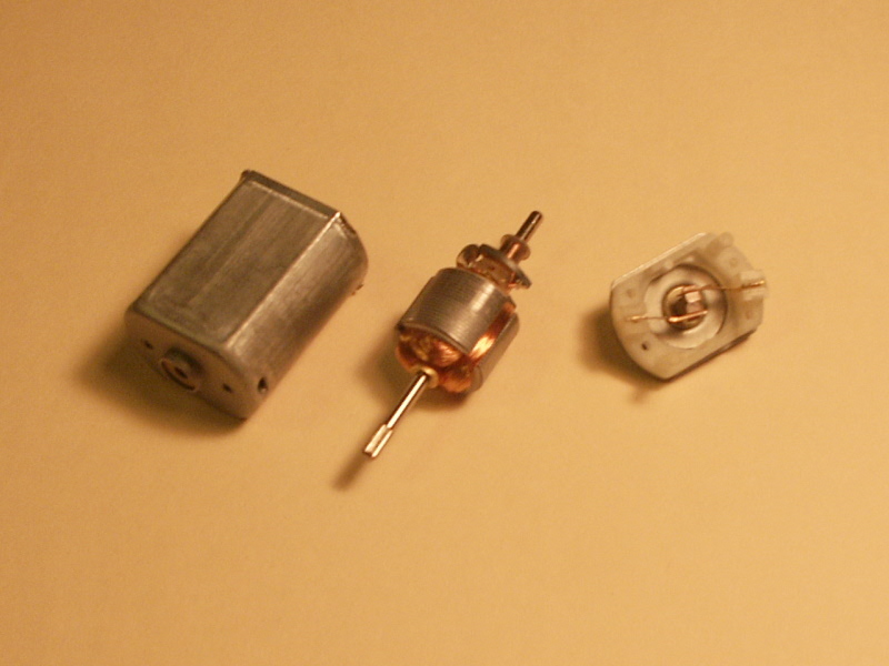
Here are some photos and drawings related to the video (click to enlarge):
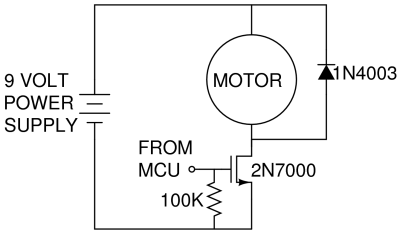
Our final motor control circuit looks like this:
Here is an overview of the nine quick motor experiments / observations made during the video. We highly suggest you try these yourself with a small DC brushed motor to get a better feel for what's going on.
Go give them a try! Particularly for the experiments where current is applied, make sure that you only use a small motor disconnected from any gearing or mechanical loads so you don't hurt yourself.
The MOSFET as a Switch
While we do talk about using the MOSFET (Metal-Oxide-Semiconductor Field-Effect Transistor) as a switch in The NerdKits Guide, we do so mostly in the context of digital logic, so there are a few extra things to think about when using a MOSFET as a high-powered switch. The basic idea is still the same: for an n-channel MOSFET with three terminals (gate, drain, and source), positive voltage applied from gate to source will allow current to flow between drain and source terminals. For the 2N7000 n-channel MOSFET we're using (which is included with the USB NerdKit), these curves from the datasheet tell the story (click to enlarge):
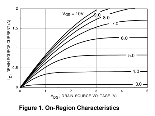
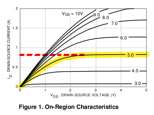
Applying a voltage at the gate selects one of these curves. With the microcontroller driving it, we're only able to choose the VGS=5V curve, leading to a maximum current of about 0.75 amps. For more information about the MOSFET as a switch, see The NerdKits Guide. For another example of using the 2N7000, see our Servo Squirter tutorial.
Bigger Loads and Power MOSFETs
For this case or for driving bigger motors, there are two more things you want to consider. First is the maximum allowed VDS, which applies when the MOSFET is off. When the switch is open, the drain terminal rises to match the motor power supply voltage. For the 2N7000, the datsheets suggests a "Drain-Source Breakdown Voltage" of at least 60 volts. This means we should not use the 2N7000 for higher-supply-voltage cases, and it's also typical to allow a safety factor, so perhaps 30-40V would be the maximum useful voltage where we can use the 2N7000 as a switch.
The second is power dissipation in the MOSFET itself, equal to ID*VDS. For the 2N7000 at 0.75 amps and VGS=5V, the figure above shows a VDS of about 2 volts, meaning that the 2N7000 is dissipating (0.75 amps)*(2 volts)=1.5 Watts. (In the triode region for small VDS, this curve gets approximated by a "Drain-Source On-Resistance RDS" as a function of VGS.) This 1.5 Watts might seem small compared to a 100 Watt light bulb, but for all that heat to be dissipated out of such a tiny transistor package would cause a huge temperature rise. Going from the 2N7000 datasheet, the "Thermal Resistance, Junction-to-Ambient" is more than 300°C/W, implying that for a 1.5 Watt power dissipation, the transistor would have to be roughly 450°C above room temperature. This would clearly just melt the plastic of transistor! It's better to keep temperature rise at most 50°C or less if possible. However, it is OK to allow the transistor to momentarily pass through such a power dissipation region, because the transistor won't heat up instantly (see the 2N7000 datasheet for more info). So if the motor very briefly draws 0.75 amps while it's starting, we're OK, but if it gets stuck or stalls, we're in real trouble! A more powerful "Power MOSFET" and a good heatsink are a must for higher-powered designs, and even for a small motor like this, an unintended stall will cause parts to overheat and become damaged. If you need to guarantee that your circuit will survive a stall (even if the motor itself might not), design it with this in mind.
If you want to control higher-powered loads, here are some other typical MOSFETs you might consider, with a table of important values:
| Part Number | Max. Current at VGS=5V [amps] | RDS at VGS=5V [ohms] | Breakdown VDS [volts] | Notes |
|---|---|---|---|---|
| 2N7000 | 0.8 | 1.7 | 60 | Used in this video. |
| IRF520 | 2.0 | 0.4 | 100 | |
| IRF730A | 0.2 | 6.0 | 400 | High breakdown -- used here. |
| FQP50N06 | 15 | 0.09 | 60 | Low on-resistance, high current. |
There are thousands of varieties out there that have different tradeoffs, typically between cost, current capability, gate capacitance, and a few other factors. Also, these are only on the n-channel side -- you may occasionally want p-channel MOSFETs for you application to put a switch on the high-voltage side of the load (but would have to think about voltage levels from your microcontroller).
As we discuss in the video, the flyback diode plays an important role in preventing large voltage spikes by providing a current path when the motor is switched from on to off. (The n-channel MOSFET itself includes a diode which helps handle the spike that may occur when the motor is switched in the other direction, from off to on.) There are two key parameters of the diode itself that are important when choosing a flyback diode:
For this demo, we used a 1N4003 general purpose diode, which is rated for 1 amp and 200 volts repetitive reverse voltage. You can also look at higher-powered diodes, like the MUR1520, which is rated for 15 amps, and also important for some applications such as pulse width modulation (PWM) speed control is its "ultrafast recovery time" tRR of about 35ns, compared to the 1N4003 which is much slower at a few microseconds. (This article provides an excellent explanation of reverse recovery time.)
Electrical and Mechanical Power
A motor converts electrical power (V*I, in volts and amps) into mechanical power (T*ω, in Newton-meters and radians/second). There are always losses, like the power lost to heating the resistive wire (I2R), and power lost to mechanical friction (Tfriction*ω), so the electrical power in will always be more than the mechanical power out.
A perfectly frictionless and lossless motor would have zero no-load current: there would be some initial current as work was done to accelerate the rotor up to speed, but once the back-EMF voltage matched the power supply voltage, there would be no more current. In reality, however, there is friction, and the no-load current is non-zero because the motor must constantly consume electrical power to make up for the mechanical power lost to friction. The motor will come to steady-state operation at the speed where the frictional and other power losses (which increase with speed) equals the electrical power in (which decreases with speed, due to the back-EMF effect described earlier). A similar statement can be made when the motor is under some mechanical load.
In the second part of the demo we use PWM, or Pulse Width Modulation, to do a very rudimentary control of the speed of the motor. The concept behind this is pretty simple to understand. Using a PWM output from one of the microcontroller's pins, you can have the pin be high some percentage of the time, and low the rest. If you are pulsing the motor on using half duty cycle (the pin is only on for half of the time) the motor is going to spin slower than if you were using a 75% duty cycle. A 100% duty cycle will cause the motor to spin at full speed (for a particular power supply voltage and load). This pulsing happens so fast that the natural inertia of the motor smooths out the on and off periods, and makes it imperceptible.
So using PWM we can get some control over how fast the motor is spinning. However, we must use caution here, because this is not actually controlling the speed of the motor, we are just controlling what fraction of the time it is receiving power. While this does roughly equate to how fast it goes, it is not true speed control. That is, if you are running at 50% duty cycle, you will not have exactly half the speed as you will at full duty cycle. In order to get true speed control you have to either completely work out the dynamics of your motor and friction and load, and how it would react to the input pulse of of different widths (which would be hard), or do some sort of closed loop control where you measure the speed of the motor and adjust your PWM duty cycle in real time to get the speed you want.
We have an explanation of how we generate a PWM pulse using the microcontroller in our Servo Squirter video tutorial.
You should also be aware that using PWM puts far greater stresses on the motor control circuit elements such as the MOSFET and flyback diode (in comparison to just switching fully on and off), because the MOSFET will be passing through its high-loss "not-a-perfect-switch" region many times per second, and also because the flyback diode will be forced to quench the inductive kick many times per second.
Other Motor Control Topics
This video and webpage covers the basics, but this topics goes even deeper. Consider: power dissipation in the MOSFET and flyback diode, finite MOSFET gate capacitance (especially with big power MOSFETs or several in parallel) and turn-on/turn-off times, diode recovery times, PWM operating frequency (high enough not to hear audibly, but low enough to not hurt efficiency), and filtering electrical noise from the motor and its brushes from getting into the rest of your circuit. Later we can look at H-Bridges, and how we can reverse the direction of the motor. Power electronics has become an entire field of its own!
It may sound complicated, but with the tools presented here, you've got the big concepts, so get out there and start playing with motors!
Source Code
Although we highly recommend you experiment with motors on your own, you can download the source code from our demo. In the same piece of code, two modes of operation are demonstrated:
The gate of the 2N7000 MOSFET is then connected to either PB2 or PB3, depending on which mode is being demonstrated. The LCD is also used for user feedback about the state of the system in both modes.
More Videos and Projects!
Take a look at more videos and microcontroller projects!
Comments
|
Did you know that you can control multiple LEDs from one microcontroller output? Learn more...
|


Copyright © 2013 by NerdKits, L.L.C.