DIY LED Heart for Valentine's Day

Valentine's Day is enough to make even the most suave guy nervous. This February 14th, use your techie skills to make a gift that is sure to win her heart. In this video tutorial, we'll show you how to make this LED Heart Valentine's Card. The card is complete with an LCD display so you can show any message you want, and also has 20 LEDs mounted around the perimeter. The code on the microcontroller (MCU) makes the LEDs blink in a way that emulates random twinkling!
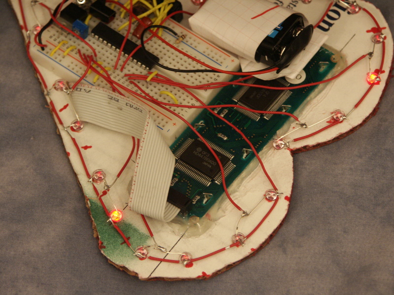
Here's what the finished product looks like:


Parts List
In addition to our USB NerdKit, you'll need:
| Photo | Part | Quantity | Description |
|---|---|---|---|
 |
T1-3/4 (5mm) standard LEDs | 20 |
We used high brightness 5mm red LEDs from abcTronics. If you order from them, please tell them NerdKits sent you! Unlike other LEDs you might see on our site, these have a clear plastic package, so you can't tell what color the LED is when it's off. But when it's on, it is red as normal. |
We also used cardboard (roughly 9" by 9"), spray paint, wire (roughly 10 feet). For the mechanical assembly, we used a handheld drill and 11/64" drill bit, a hot glue gun, and a soldering iron.
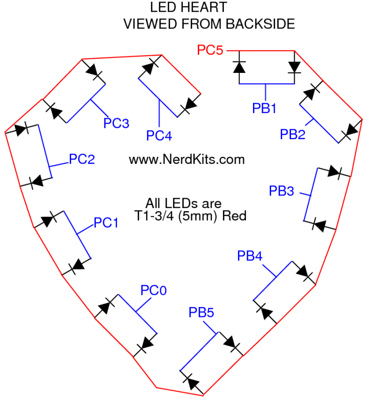
LED Wiring Plan
One wire runs along the outside of the cardboard, and this is like the row wire in the LED Marquee project, constantly alternating between high and low voltages. Then, individual wires are run to pairs of oppositely-connected LEDs. This allows for 20 LEDs to be controlled from 11 signal wires. Click to enlarge:
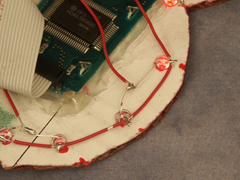
Physical Construction
Click any photo to enlarge:
Display Interrupt Handler
Much like our LED Array Project, this heart uses a timer interrupt and an interrupt handler to to handle the switching back and forth of the row driver. The interrupt handler sets the single row driver in the forward direction, and then turns on all the forward LEDs. When the timer fires again, the handler reverses the direction of the row driver, and turns on all the appropriate backward LEDs.
Randomized Twinkling
In order to complete the effect on the card, we decided to emulate twinkling of the LEDs. To do this, we take advantage of the duty cycle of the LEDs. Remember how we are switching the row driver back and forth in order to drive first the forward LEDs, then the backward LEDs; this allows us to define a duty cycle for each LED. Every time we switch back and forth, we increment a counter that rolls over to zero every 64 ticks. For each LED in our heart, we store a brightness level between 0 and 64. This brightness level defines the duty cycle (the number of cycles we will keep the LED on out of 64). If the LED is on for only one cycle it will be very dim, but if it is on for all 64 cycles, it will be on at maximum brightness.
The twinkling code sits in a while loop that iterates through an array that represents the state of each LED. Each LED can be off, brightening, or dimming. At each iteration it chooses a random number, and with a 1/10 probability it switches the state of the LED from off to brightening. It then increases the brightness of all the LEDs that are brightening and decreases the brightness of all the LEDs that are dimming. Once the LED gets back to its minimum brightness level, it switches the state back to off. This creates the desired effect where LEDs seem to randomly begin twinkling. To further the effect, the code also randomizes the maximum brightness they reach, which makes some LEDs flicker on and off quickly, while other LEDs go through a long cycle and reach higher brightnesses.
Overall, the effect is difficult to capture in the still photos, but it's easy to see at about 3:05 to 3:23 in the video.
Source Code
You can download the source code here. Start with a standard NerdKits project and Makefile (included with the kit) and plug in this source code.
More Videos and Projects!
Take a look at more videos and microcontroller projects!
Comments
|
Did you know that a flyback diode is important when driving a motor or any inductive load? Learn more...
|


Copyright © 2013 by NerdKits, L.L.C.