Multi-Panel LED Array with SPI

The LED Array Project has been one of the most popular projects for us here at NerdKits. Numerous customers have taken the idea and done some really neat modifications to it. Despite its versatility, and usefulness as a great intermediate learning project, the LED Array as originally designed had one drawback: you were limited to 24 columns of LEDs.
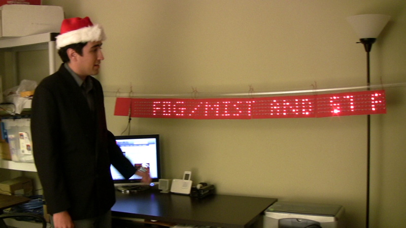
In this project, we put a new twist on our old idea, and modified the LED Array into a giant multi panel array -- theoretically capable of driving 1200 LEDs (or more if you are creative!). The project uses the SPI bus to communicate between different chips, so in addition to the awesome new LED sign, we also go over how to use another useful piece of the ATmega168 microcontroller.
Click any photo to enlarge:

The SPI Bus
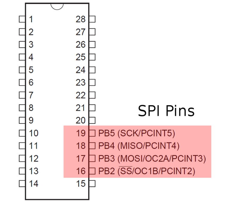
In order to be able to have one master chip that feeds data to many other chips, we made use the SPI module. SPI stands for Serial Peripheral Interface, and is a standard protocol that many digital components can use to communicate with each other. The SPI protocol is a 4-wire protocol. It uses one wire to send data from the master to the slave (MOSI, which stands for Master Out / Slave In), another one to send data from the slave to the master (MISO), another one for the clock (SCK), and one for the master to select which slave it is talking to (SS). When a master wants to send data to a slave, it first pulls the SS line going to that particular slave low. It then begins moving the clock line and will read and send data on the MISO and MOSI lines.
The inner workings of the SPI bus are abstracted away by the SPI module, although we still recommend reading the datasheet (starting at page 162). It goes into the details of the different ways you can configure the module to run. The SPI protocol can run in many different configurations that change which edge of the clock the data is read on, whether the clock starts low or high, and the clock frequency among other things. Since we are just communicating between ATmega168 chips, all the default settings work, but if you wish to talk to a different device via the SPI bus you might need to set some configuration bits.
Once the SPI bus is initialized, sending a byte is as easy as writing the data to the SPDR register. The module will clear the SPIF bit when the data is done transmitting. One the receiving end, the module can be configured to fire an interrupt when a new byte is ready to be read, or you can watch for changes in the SPIF bit. We opted to use the interrupt, since our array should otherwise be busy updating the physical LEDs.
One big advantage to the SPI bus is its speed. We clocked this system at CLK/16. We are using a 14.7456MHz clock, so the actual SPI clock frequency is just over 900kHz. At that rate, sending a whole frame of 21 bytes takes only about 180 microseconds. This is plenty of time for us to update the array at about 60Hz and still have plenty of time to run the LEDs correctly.
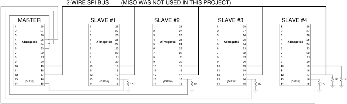
Click to enlarge this schematic showing how the 5 microcontrollers are connected together:
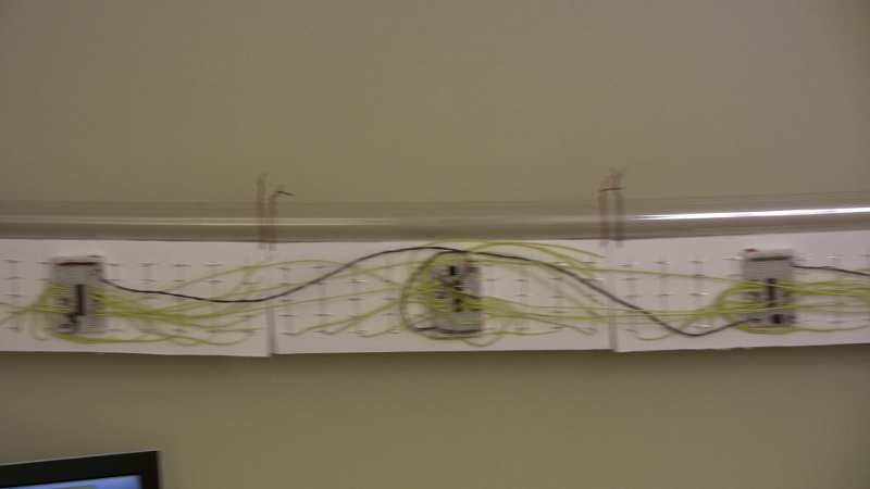
Panel Construction
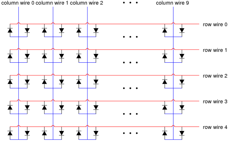
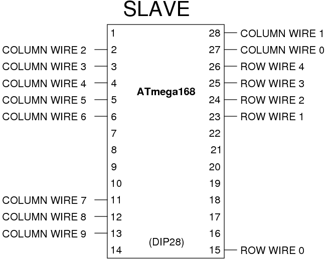
The physical construction of the array was pretty much exactly the same as the one detailed in the LED Array Tutorial. The only major difference is the size of each array: instead of a 24 column by 5 row array, each panel in our multi panel array is 20 by 5. As is usually the case in engineering, the extra functionality did not come without its trade-offs. The SPI bus does use 4 wires, so we lose the ability to use those to drive LEDs. Since we are not using the UART (serial port) on the panels to receive data, we can use them to drive LEDs. So we lose 4 wires, but we gain 2 from the serial port for a net loss of 2 pins. Due to our multiplexing scheme this amounts to a loss of 4 LED columns. It is unfortunate, but it is a small price to pay for the ability to extend the array arbitrarily.
Since the SPI pins are pins we previously used to use to drive row wires, we had to shift the row and wire columns around the shift. The wiring diagram shows the new wiring for the slave panels. These changes also needed to be reflected in the code.
Click to enlarge:
The Code
There are two sets of microcontroller code for this project: one program for the master chip, and a separate program for the slave chips. All of the display panels (slave microcontrollers) all run the exact same code.
The code for this project mostly comes from the original LED Array Tutorial. The interrupts to drive the LEDs and all the font logic is exactly the same. We added a new interrupt handler that fires when an SPI byte is ready to be read on the slaves. The handler simply adds the data to the next spot in the buffer. We also have a special byte 0xFF that is sent from the master when it is done sending a whole frame. When a slave recieves the byte 0xFF, it flips the two data buffers.
The code running on the master uses all the old font rendering code, and listens over the serial port for new characters the same way the original LED Array did. The master keeps the pixel data for the entire LED Array in its own large data array. We introduced a new timer interrupt that fires about 60 times per second. When this interrupt fires it goes through the slave array panels one by one and sends them the corresponding slice of the big data array it holds.
Aside from that, there are only a few initialization routines that we added to properly set up the SPI module.
Notice how the new array follows pretty much the same paradigm that the old setup did, except that now there are many panels each with a data array that thay manifest onto LEDs. The communication to the outside world has now been transfered to the master chip. The system as originally designed was modular enough to allow us to split it in two and shift half the functionality to a completely different chip!
You can download the full source code for this project to take a look at how we did it. The code that runs on the master chip is ledarray_master.c, and the code on all the slaves is ledarray_slave.c. The extras folder contains the python scripts that communicate over the serial port to the NerdKit, grab RSS feeds, and the script we used to display the current music track in the video.
Double Buffering
Since the SPI bus can only transfer one byte at a time, there is some time delay between when a slave panel begins receiving data, and when a full frame has been transferred. If data were to be displayed to the array as it was being received there might be a noticeable flicker as the panel was filled in from left to right. In order to alleviate this, we employed a technique called double buffering. Instead of writing directly to the data array that holds the pixel data, we instead write to a different array that is exactly the same size. While the data is being transferred, the LED Array continues to display the old data. When a full frame has been transferred, and the data is in the second data array, we use use a little bit of C pointer magic to flip the two arrays, such that the LEDs are now being updated using the new data, and what what used to be the old data array is now our data buffer. The ability to swap pointers to arrays like this is one of the benefits of using a low level programming language like C.
Long Wires and Transmission Line Issues
If you look closely at the schematic in the SPI section above, you'll see six 1K ohm resistors being used in seemingly odd places on the schematic. This is one of the occasional times when physical location on a schematic indicates something about where that component should physically go -- the 1K resistors should be at the slave panels as indicated.
If you build the display for yourself but omit these termination resistors, you may find unusual / erratic behavior, particularly with the arrays physically most distant from the master. This is the first project in which we're trying to send digital signals over wires more than a few inches long. Even though our data transmission rate is only about 900kHz as indicated above, the edge times are very fast, with transitions from digital high to low (or low to high) happening as fast as the microcontroller can make them happen -- on the order of a nanosecond! This means that there are frequencies on the order of ~1 GHz being represented in the digital signal, and since the speed of light is 3e8 m/s, the wavelength of a signal at 1 GHz is about 0.3 meters, or about one foot! These figures are all rough estimates, but we are clearly trying to send digital information over a distance that is at the same scale or larger than the wavelength. This means we have to start treating the wire like a transmission line where signals take a finite amount of time to move from one end to another. But the real problem is that there are issues with signals reflecting back and forth from each end before they settle out to the driven voltage.
To prevent these reflections from interfering with our digital communications, it's important to "quench" them, and adding the termination resistor does that. If we cared more about being precise with analog signals and terminology, we'd want an exact impedance match between the "transmission line"'s "characteristic impedance" and the termination resistor, but in practice we don't know what that value is in this case (although some interesting properties of the universe make it on the order of 377 ohms within an order of magnitude or two!). We chose 1K as a reasonable resistance that wouldn't add too much extra power consumption but would still reasonably alleviate transmission line issues.
This is an advanced topic, but if you're curious, here's some further reading:
How do I build it?
You'll first want to take a look at our USB NerdKit plus LED Array Kit. You can then purchase extra sets of parts from our store.
More Videos and Projects!
Take a look at more videos and microcontroller projects!
Comments
|
Did you know that there are Power MOSFETs for switching big loads on and off? Learn more...
|


Copyright © 2013 by NerdKits, L.L.C.