Servo Squirter

In this video, we'll show you a simple project where we connect a hobby R/C servo to a small water pump, and control both from the USB NerdKit. Using input from the connected computer, you can aim, and fire a stream of water. The video also introduces topics like Pulse Width Modulation (PWM), including how hobby servos share a common protocol (1.0 to 2.0ms pulses), and how to use the ATmega168 to generate these pulses. Perhaps you can add another servo, and use this to water your plants?
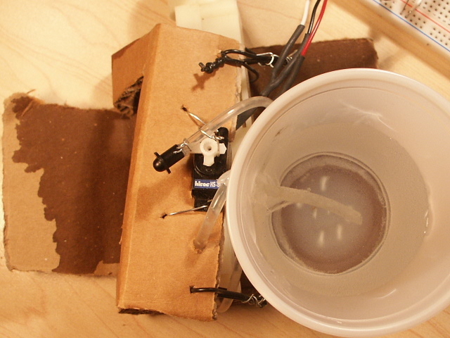
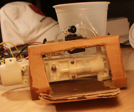
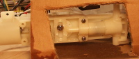
Here are two photos of the mechanical assembly: (click to enlarge)
Schematic
The first part of our circuit just connects to the servo. This is simple here: one wire from the microcontroller to the servo. There are a few different color labelings depending on the manufacturer, so check before trying this.
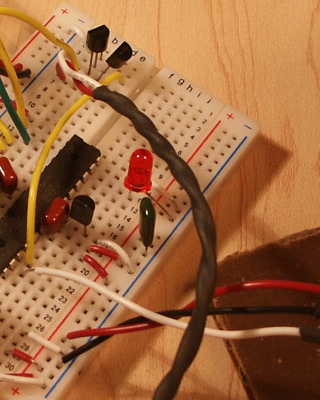
Click below to see larger images of the schematic, etc.:
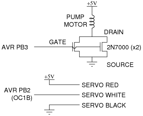
The second part of the circuit allows the microcontroller to switch the pump motor on and off. The ATmega168 chip itself only allows 40mA max into or out of any pin, but our pump requires closer to 1000mA! So in order to control this bigger load, we've chosen to use a bigger transistor, the 2N7000. We explain the basics of using MOSFETs (Metal Oxide Semiconductor Field Effect Transistors) as switches in the NerdKits Guide, but to summarize: bringing the Gate voltage above the Source, we can allow current to flow from Drain to Source. From the 2N7000 datasheet, we've extracted Figure 1, which shows the relationship between drain current and drain-source voltage for different gate-source voltage settings. There are a few important things you can learn from this graph:
And now you've actually learned about all three modes of MOSFET operation: cutoff, triode, and saturation.
Because our gate control is digital (+5 or 0), we're only concerned about the curve highlighted in yellow, for VGS=5V. Normally, using a MOSFET as a switch generally involves the triode mode of operation, because the MOSFET dissipates power PD=ID*VDS, and a good switch should dissipate little power in the switch itself. But in this case, we're dealing with a motor, and motors tend to require lots of current (with little voltage drop) when they're first starting up. So for the first second or two, the MOSFET will operate with high VDS, and will be limited by its maximum current -- about 800mA from the red dashed line we've drawn on the datasheet. We found that this wasn't enough to get the pump started, so we used a little trick and put two MOSFETs in parallel. This way, they share the current, and can effectively sink about 1600mA together.


Also due to the high power requirements of the pump, we used a wall transformer with higher current output. If you have a wall transformer with greater than 5V output -- maybe 9V or 12V -- then you can connect one side of the pump motor directly to this higher DC voltage. This will avoid having the 7805 linear voltage regulator burning lots of extra power.
Parts List
In addition to our USB NerdKit and a wall DC adapter, you'll need:
| Photo | Part | Quantity | Description |
|---|---|---|---|
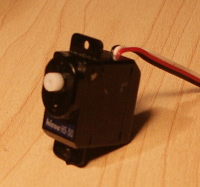 |
Hobby Servo, Hitec HS-50 | 1 | This servo is a fairly standard small hobby servo, available from Amazon.com among other places. |
 |
Water pump, low voltage piston-type | 1 | This pump actually has some serious kick, and throws pulses of water easily 8-10 feet in a narrow stream. |
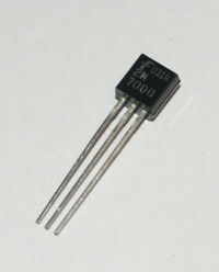 |
Small n-channel MOSFET, 2N7000 | 2 | These are nice, inexpensive transistors that we use for switching bigger loads. As of 4/07/2009, four 2N7000s are now included with the USB NerdKit! |
We also used cardboard, some steel wire, a plastic cup, and hot glue to build the structure.
PWM Registers and Calculations
In the video, we talk about two levels used by the timer/counter module: the top value, and the compare value. Both of these are important in generating the PWM signal you want.
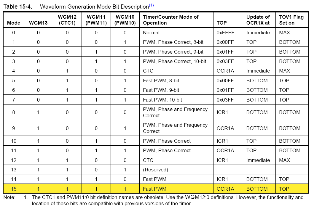
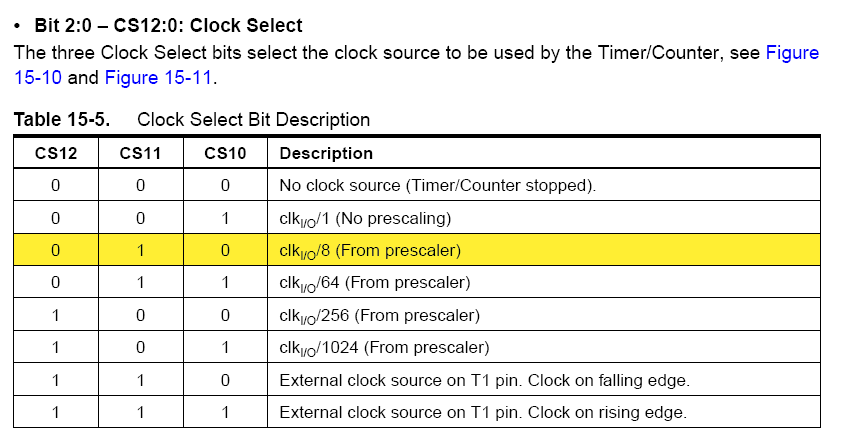
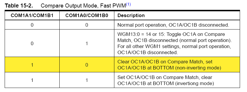
But to activate your ATmega168's PWM output in the first place, we have to set up a few registers. First, we select Fast PWM mode with OCR1A as the top value, which lets us arbitrarily set how often to start a new pulse.
Then, we set the clock to run with a pre-division of 8, which means that the counter will increase by 1 every 8/(14745600 Hz) = 542 nanoseconds. Since we have 16-bit registers for this timer, this means we can set our overall signal period to be as high as 65536*542ns = 36 milliseconds. If we used a bigger division number, we could make our pulses farther apart (which doesn't help in this situation), and we'd lose resolution. If we used a smaller division number (such as 1), we wouldn't be able to make our pulses at least 16 milliseconds apart, as our servo expects.
Finally, we set the Compare Output mode for a "non-inverting" PWM output, which is described in our video. We also set the pin PB2 to be an output pin -- not shown here, but it's in the code.
Click to enlarge these shots from pages 132-134 of the ATmega168 datasheet, with our register value selections highlighted:
Serial Port Communications
In the NerdKit, we use the serial cable to send commands, and information to the computer. It is possible to write simple programs in most programming languages that can communicate over the serial port to the NerdKit. However it is much simpler to use a terminal program to do the serial communication for us. This way you can just type on the keyboard, and see the response from the NerdKit.
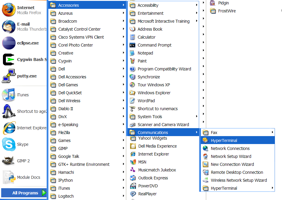
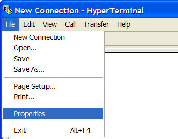
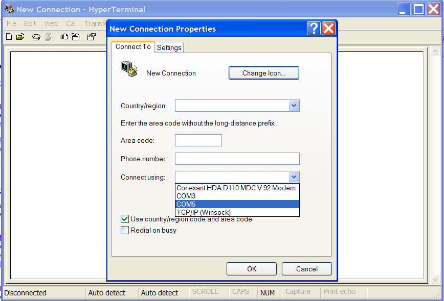
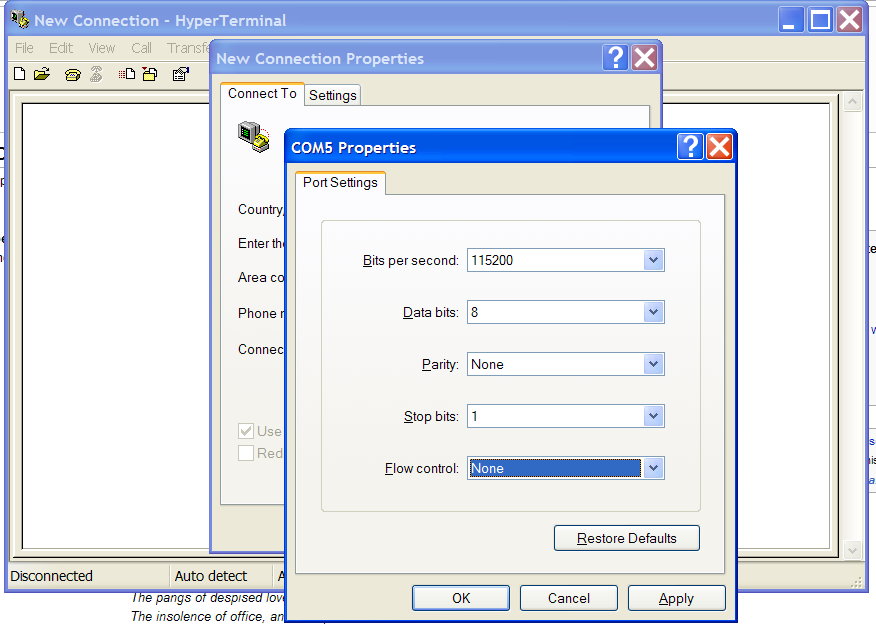
If you're using Windows XP or earlier, HyperTerminal is included, and should be in your Start Menu under "Start -> Programs -> Accessories -> Communications". When you first open HyperTerminal, it asks you to set up a connection. Cancel out of those, untill you are at the main HyperTerminal sceen. You'll have to set up HyperTerminal, choosing the correct COM port, and setting the port settings appropriately to work with the NerdKit. Follow the screenshots below to get right HyperTerm setup.
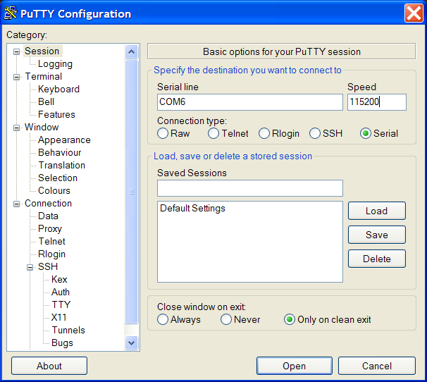
If you're on Windows Vista, HyperTerminal is no longer included. In this case, go download PuTTY (Windows installer). Use the connection settings below to set up Putty, using the proper COM port.
After entering the Terminal application, type "screen /dev/tty.PL* 115200" to start communicating over the serial port.
On Linux, we use "minicom" to talk to the serial port. To start, run "minicom -s" at the console to enter minicom's setup menu. Go to "Serial Port Setup". Set the parameters as follows:
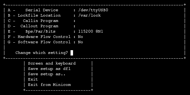
Then, hit escape and use the "Save setup as dfl" to save settings as the default. You should now be able to hit "Exit" and use minicom for talking to the NerdKit.
Source Code
You can download the source code here.
More Videos and Projects!
Take a look at more videos and microcontroller projects!
Comments
|
Did you know that you can make a huge, multi-panel LED display? Learn more...
|


Copyright © 2013 by NerdKits, L.L.C.