NEW: Learning electronics? Ask your questions on the new Electronics Questions & Answers site hosted by CircuitLab.
Everything Else » Suggestions and ideas for Rick's Nerdkits Project board!!
|
November 13, 2012 by Ralphxyz 
|
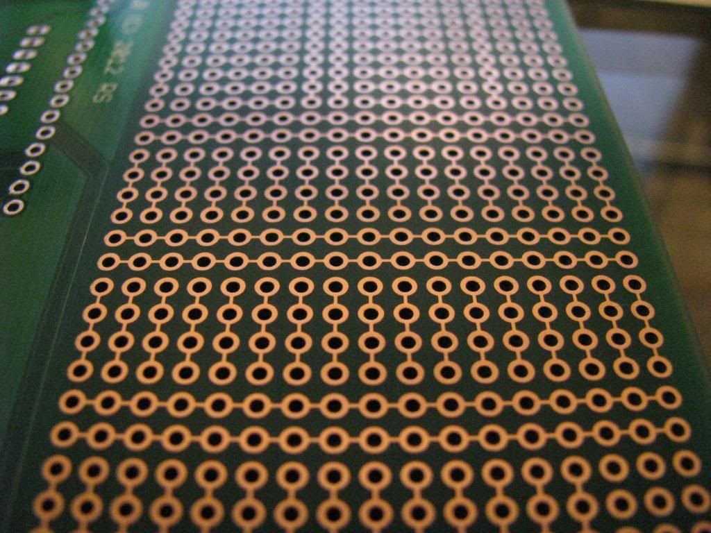
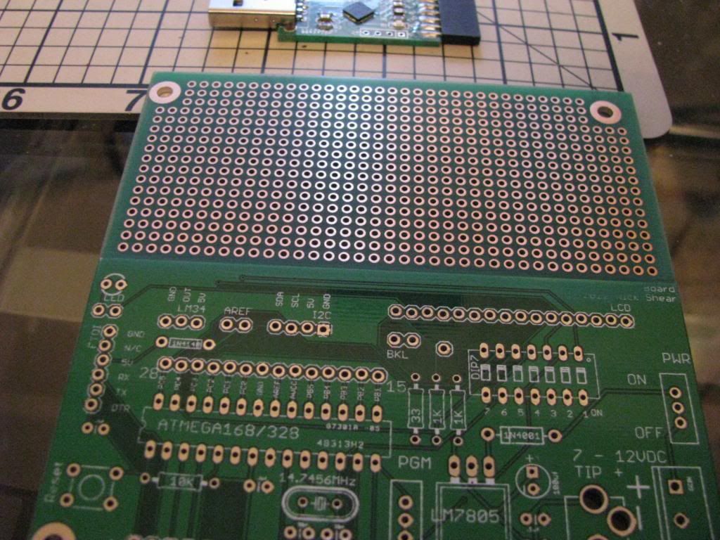
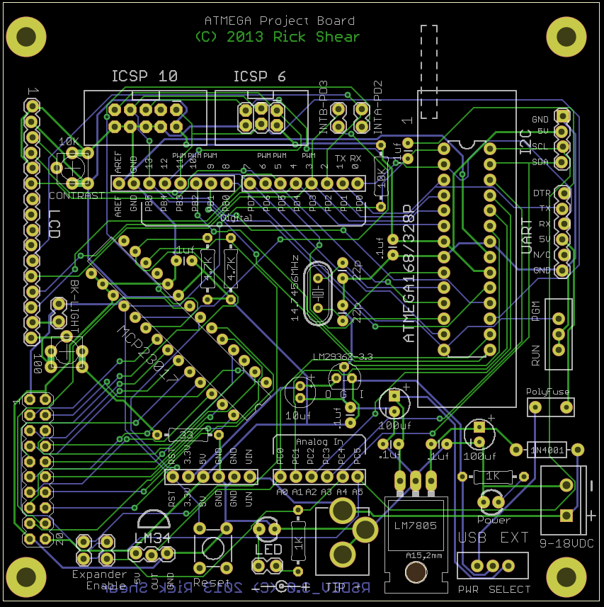
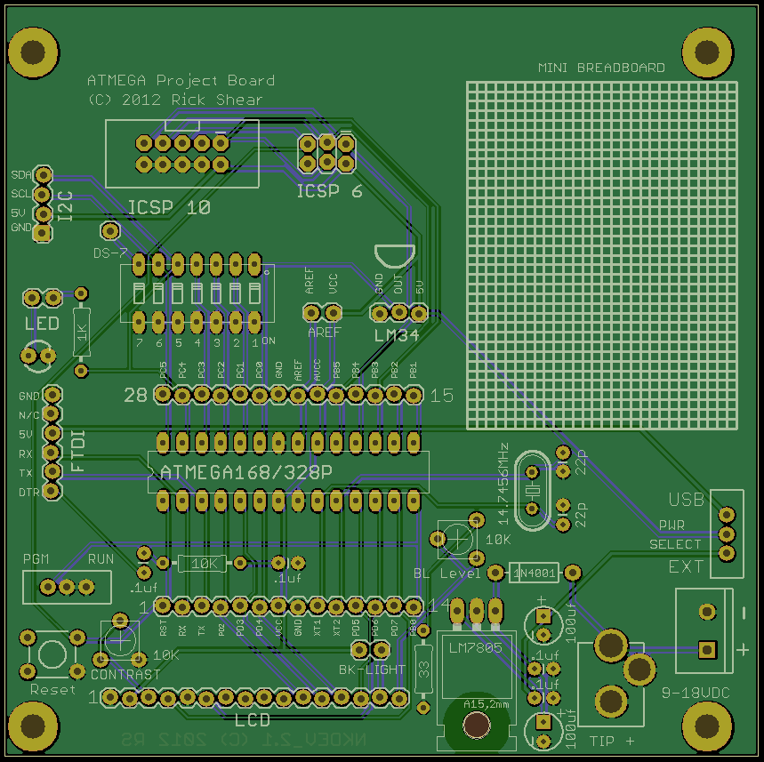
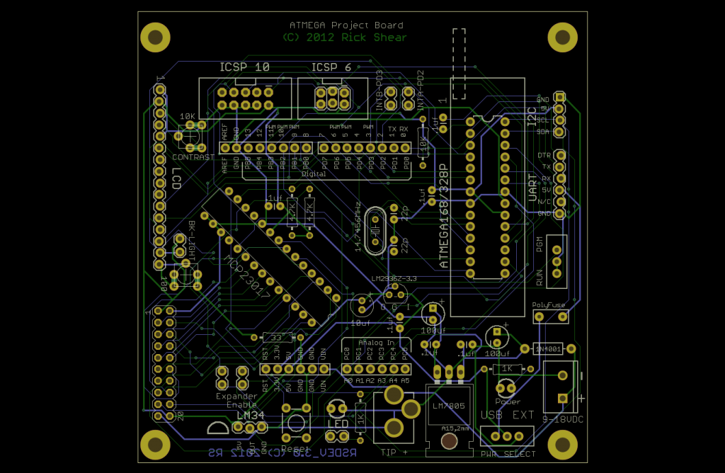
Rick opened himself up for this when he asked: Here is Rick's board:
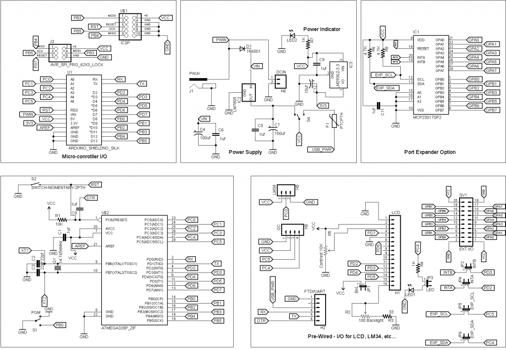
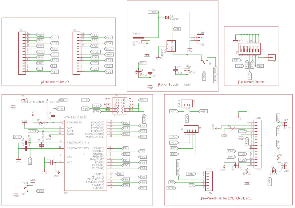
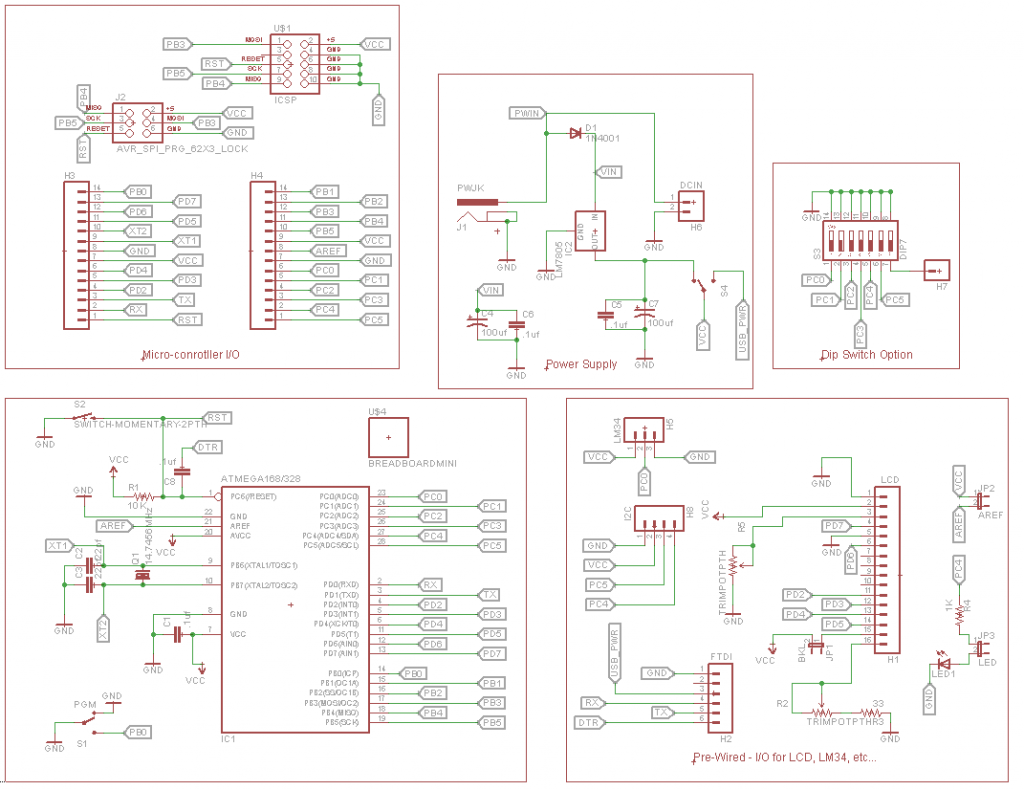
and here is the schematic:
So my first one is I'd like to use a potentiometer or variable resistor (what is the difference?) for the LCD contrast. Next I like to not put the DIP switch to ground but go to the proto area so that I could switch things on and off. In conjunction with the thought of the proto area I'd like to have a +/- buss in the proto area. I'd like a six pin ISP header the Atmel AVRISP mkII In-System Programmer (ATAVRISP2) comes with a six pin cable as do a lot of third party programmers. Of course the AVRISP mkII does have a 10 pin header that you can add a cable. A lot people do not know about the header so they think they have to have six pins.. And now just to make it more interesting for Rick how about a SMD version? I am building the board as we speak so I know I will have more ideas. Ralph |
|---|---|
|
November 14, 2012 by Rick_S 
|
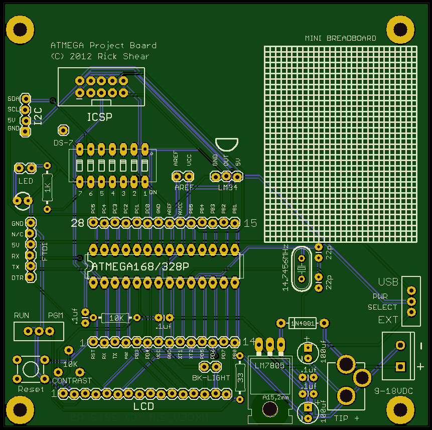
Paul, Ralph & anyone else interested, What do you think about these changes. I moved the LCD connector to the edge. I added a contrast trimmer. I removed the prototype area and replaced it with a spot for a mini breadboard. I also spread the components a bit farther from the mcu socket so a zif socket will fit. Here's an image of what the board would look like.
What do you guys think?? Rick |
|
November 14, 2012 by pcbolt 
|
Rick - I like the idea of the mini breadboard. If it was me personally, I'd add a shift register to interface with the LCD to free up some pins, but I understand your concept of making it compatible with the Nerdkit guide and projects. BTW, do you use a company that makes custom PCB's for each design you want or is it a "Batch PCB" concept of sending in your files and waiting for a other designs to come in so a full board with each design can be made? Also, do you have a link to them? |
|
November 14, 2012 by technogeek3000 |
idk i like the idea |
|
November 14, 2012 by technogeek3000 |
maybe if the nerdit would work with LINUX OS and color pixels anyone like this idea? |
|
November 14, 2012 by Rick_S
|
I have used batch PCB but my last two jobs I had done were from a Chinese company called iteadstudio. Rick |
|
November 14, 2012 by Noter 
|
Rick, I like the mini breadboard too. I've used them a fair amount and I like them. Sometimes I wish there was a power rail. Another well placed hole and either a trim pot or resistor could be used. I'd use the trim pot but some folks may be fine with the resistor. The reason I like to adjust the backlight is that when it is full on it draws enough current to heat up the regulator. I used to put a heat sync on the regulator but now I just turn down the brightness on the backlight. Overall great improvements! I'd like one please, where do I sign up. Do you accept paypal? Paul |
|
November 14, 2012 by pcbolt
|
Rick - I checked out the iteadstudio site and they have some pretty good prices. If you make your protoboard, will it be open source so we can get free ones if we design something new? Noter - Do you have a thread started for your Bluetooth project? I got some chips and may have some questions. |
|
November 15, 2012 by Rick_S
|
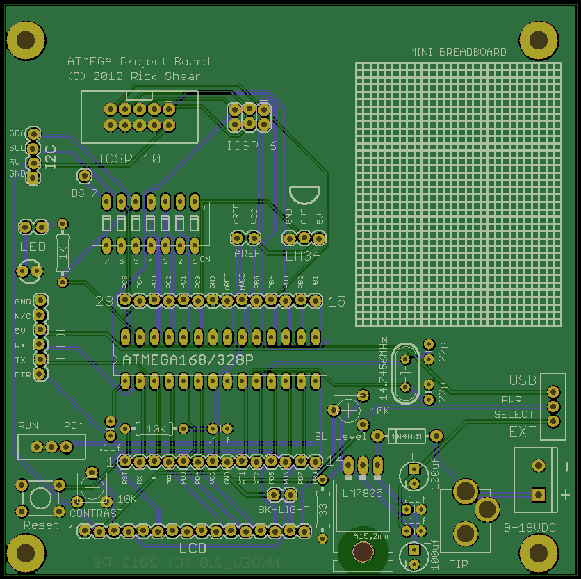
I added the ICSP 6 Header and a trimmer for the backlight. I left the resistor for the backlight in circuit that way you cannot send too much current through. Any more thoughts??
Rick |
|
November 15, 2012 by Noter
|
Rick - the new design looks good to me! pcbolt - I started a thread for questions/comments related to the bluetooth library article. Paul |
|
November 15, 2012 by Rick_S
|
I'll check here when I get home from work, and if it looks good to everyone else, (or anyone else), I'll look it over once more and order a batch. |
|
November 15, 2012 by Ralphxyz
|
Rick, how hard would it be to reverse the RUN/PGM switch? Especially since you are trying to match the Nerdkit. I want some!! Ralph |
|
November 15, 2012 by Rick_S
|
That'd be an easy change, I just figured we always tell people to slide the switch toward the micro for program mode, that's why I put it that way. But if the consensus is to turn it around, I'll do that. Anyone else?? |
|
November 15, 2012 by JKITSON 
|
RICK I will take a couple just as you have it. Let me know when and how much. Zip code 86040 Fantastic job.... Jim |
|
November 15, 2012 by Rick_S
|
OK Program switch is turned around. I'll send the board of to be made in a bit. I'll check here first though so speak now or forever hold your peace...
Rick |
|
November 15, 2012 by Noter
|
Hi Rick, I'm looking at the BL trim pot and it looks like VCC goes to one of the pins. Am I tracing the signals correctly? Paul |
|
November 15, 2012 by Rick_S
|
Yes, VCC one side, GND the other, Wiper to the 33 ohm resistor to the cathode of the BL... I hope that's right, 'cause I just placed the order... |
|
November 15, 2012 by Noter
|
I think that will allow .5 ma current through the 10K trim pot and 33 ohm resistor all the time, even when the BL jumper is off. Am I looking at that right? |
|
November 15, 2012 by Rick_S
|
Yeah, I realized after I typed that it was a mistake. I changed the circuit so the wiper is now connected to the other end so the resistance will be between ground and the backlight and vary from the fixed resistor to 10K Plus the fix... I sent the correction to the board maker but I don't know what they'll do. Hopefully they will use the corrected version... Rick |
|
November 15, 2012 by Noter
|
Did you catch the same thing on the contrast trim pot? Sorry I didn't look closer earlier and I've been out most of the day. The contrast trim is an easy fix, just cut the trace to VCC. Probably the easiest thing is to snip the pin on BL trim pot so that it doesn't make contact. It will be interesting to see if they can get your corrected version in for the board. Last time I ordered from OSHpark I did the same thing a couple of hours after I submitted the order. Fortunately they are willing to make the change unless it's already been added to the panel so I lucked out. Of course now that I have the boards I realize a few other things I didn't get quite right anyway. So goes is the prototype cycle. Paul |
|
November 15, 2012 by Rick_S
|
Yes I did do the same there. I'm not going to try another correction though. Like you said, it'll ba an easy enough fix afterwards. Maybe I'll get all the bugs worked out on the next order Rick |
|
November 15, 2012 by Ralphxyz
|
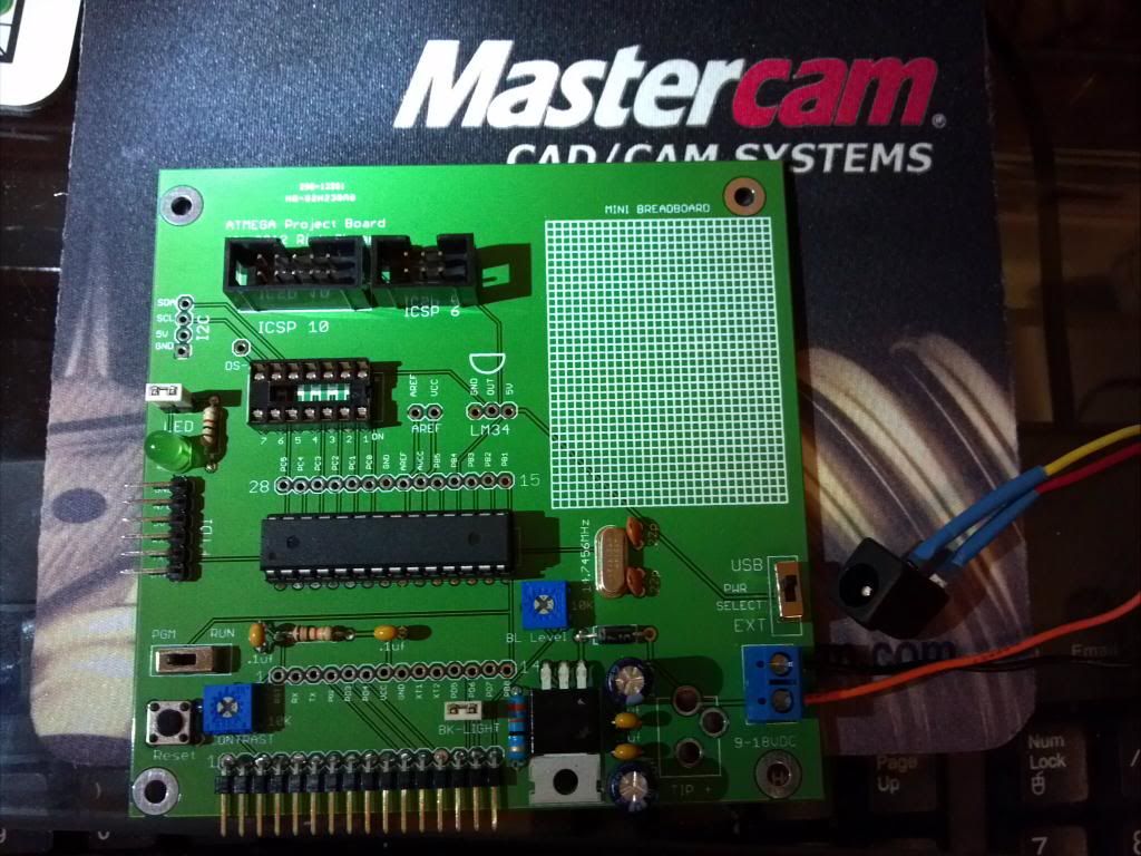
Well I have a new (older version) board working!!
I used a 1k pot in place of the 1k contrast resistor, also I did not test the spst switches for toggle direction so they are installed backwards. BUT IT WORKS!! Next I am going to add Darryl's (sask55) opto-isolation USB circuit in the proto area. I actually like the proto area as I can make the circuit permanent if it was a mini breadboard I'd have the problem of loose wires. So I should have a dependable base to work from and not have to worry about loose or missing wires. Of course I want some of the new version. I will probable add a proto board shield like an Arduino for the new version. Rick, do you still have my address? Ralph |
|
November 15, 2012 by Rick_S
|
Glad to see it's working. I should have your address still. It'll be a month or so before the new boards arrive though. Rick |
|
November 16, 2012 by Rick_S
|
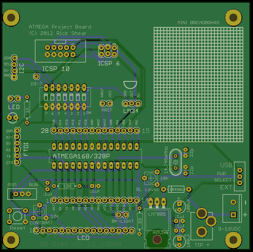
Well I may have a second chance. It seems I accidentally used the wrong CAM processor in eagle when I made up the gerbers and they needed them corrected. So I changed the Contrast pot wiring as well. Hopefully all will be good now. Here's a shot of the most current board.
Here are the schematic changes:
Rick |
|
November 16, 2012 by Rick_S
|
Ralph, for the dip switch, I installed an IC socket that way I can plug or unplug the dip switch as needed. |
|
November 16, 2012 by Noter
|
Wow, two wrongs do make a right! ;-) Glad it's working out. |
|
November 16, 2012 by Ralphxyz
|
Hey Rick thanks, re the dip switch. When I went through the Nerdkit dip switch project I didn't get it, I really had a hard time with it. besides turning the LCD around (which I still do not understand) I also put LEDs and resistors on the grn side of the dip switch. This helped me to visualize better what was happening. So I needed access to the low side of the dip, that's why I suggested sending the low side to the proto area. Of course now you have eliminated the proto area so the low side goes to ground making this a mute point. Well I have one board working so that is good, now I cannot complain about the breadboard messing me up. Oh I also need to add your ISP board to the protoarea, again thank you for the ISP board. Ralph |
|
November 26, 2012 by Rick_S
|
Just got notification that the boards shipped... In 2 or 3 weeks they should be here... If after I build one, it passes all the functional tests, I'll put the eagle files up for download. Rick |
|
December 06, 2012 by oldbot |
Hi Rick - I've been using standard prototype boards to build nerdkit-based projects. I know what a time killer it is to do everything yourself. Your board looks like it will save a lot of time, and will be more reliable too. It would be a great service if you made these boards available to the rest of us. Maybe you could sell them through the NerdKits store. |
|
December 06, 2012 by Rick_S
|
Once the boards come in and I have tested the function, I plan to make the files available. Never really thought about selling them, although I always wondered why the NK guys never had a dev board. I do think it'd be cool to sell them as a kit through their store, but since I'm just another hobbyist like you, that probably won't happen. ;) Rick |
|
December 08, 2012 by Rick_S
|
Well, the boards came in today, and I started to dry fit components. Now I want to kick myself. I put the LCD on the same side as the coax power jack. So if the LCD is in place, the coax jack won't be able to be used. Doesn't make the board un-usable, just frustrating. Oh well, I'll build this in the morning and make sure it work electrically, then on to the design for REV 3... What's the old saying... If at first you don't succeed, try, try again.... and again... and again.... ad infinitum. I'll post photo's once it's built. Rick |
|
December 15, 2012 by Rick_S
|
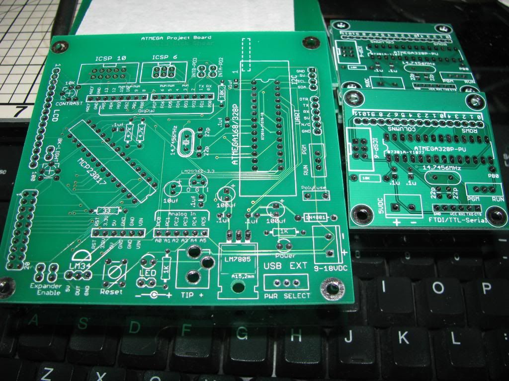
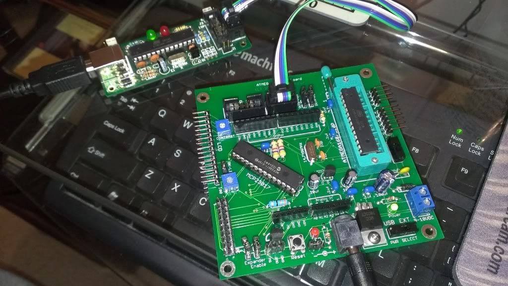
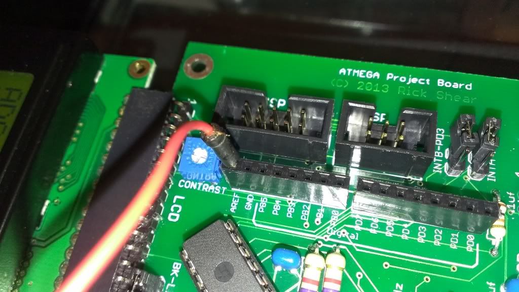
Well, after a much longer delay than I anticipated, here is a photo of the partially built Rev 2 board. I ran into a couple of other problems as I went. Some just minor irritations, others design mistakes and another a mystery to me. Here is the photo.
The board does function. The ICSP 10 pin jack works as expected. I couldn't test the 6 pin as I don't have a 6 pin cable right now. Now for the problems/bugs.
Well, I guess it's back to the drawing board to work on Rev 3. I'm going to fix the jack placement issue, and I'm thinking of changing the 28 pin headers to an arduino header layout so shields could be mounted. Any other input?? Rick |
|
December 15, 2012 by Ralphxyz
|
Definitely go for the Arduino header layout, that was going to be one of my suggestions. Ralph |
|
December 15, 2012 by Rick_S
|
Paul, what value pots do you use for contrast & backlight dimmer? |
|
December 15, 2012 by Noter
|
I've been using 10K trimmers just because that's what I have. They are the multi-turn type though so there is finer adjustment which helps when near an end. One of my displays actually works ok with no contrast resistor at all but can be made a little better with a turn or two on the trimmer. -Paul |
|
December 15, 2012 by Ralphxyz
|
since the Nerdkit comes with a 1k resistor for LCD contrast why arn't you just using a 1k pot? You also probable could use a 100 ohm pot for the LCD backlight. I also have not used any resistor for the lcd but noticed that my voltage regulator was running warmer than with a resistor, even though 30 ohms isn't a lot of resistance it did seem to make a difference. Ralph |
|
December 15, 2012 by Noter
|
Like I said, I'm using the 10k's just because that's what I have in my parts box. No other reason and they work fine. Since they are multi-turn it's just as easy to adjust one for 30 ohms as for 3000 ohms. Interesting that you can change LCD contrast and observe a warm up on your regulator, LCD's are very low power. I haven't seen that but have noticed a bright backlight really heats up the 7805. |
|
December 15, 2012 by Rick_S
|
I have some 1K as well as 100 Ohm now so I'll experiment a bit. Paul, any thoughts why the arduino auto reset wouldn't work in my circuit?? |
|
December 15, 2012 by Noter
|
I don't have my FT232 hooked up at the moment but if the PC/FT232 disables the DTR port between uses then maybe it when it enables the port it is not high long enough (or at all) to bring the capacitor to 5v. If that's the case the capacitor could be holding the charge from the previous time and have nothing to pulse through. Try a 100k pull-up resistor from DTR to VCC to ensure 5v on both sides of the capacitor so when DTR goes low there is a change to pass thru. Another possibility is if DTR is only 3.3v instead of 5v that may not be enough change to reset the avr. |
|
December 15, 2012 by Rick_S
|
What's odd is that the same FTDI adapter works with another board (Netduino). My circuit ( from what I can tell ) is the same as other boards from Sparkfun and others... I'm at a loss. |
|
December 15, 2012 by Noter
|
Maybe the reset is working but the bootloader is not? Can you tell if the atmega resets? Maybe the bootloader is timing out too quickly and running the app? Can you disconnect the FT232 and reset with GND to DTR manually? Probably will have to charge it to 5v first. If not, cold solder joint or bad capacitor. |
|
December 15, 2012 by Noter
|
Rick, To change the subject - I recently received a board that was going to have a ZIF connector and although I left enough space, the ZIF pins would not fit into the holes. I can't tell for sure looking at your pictures but you may need to copy the atmega package in eagle to make a new device with large holes like are used for header pins. -Paul |
|
December 15, 2012 by Noter
|
Rick, I hooked my FT232R to see what it does. It resets a target atmega fine as long as the PC host uses the DTR correctly. The particular emulator I tested with had a menu item to toggle DTR and I had to use that to get it to work because that program did not reset DTR back to 5v on exit. Here's the steps I followed in my test -
If you disconnect the FT232 usb you can verify your hardware by touching the DTR with 5v and then touch it with GND. The atmega will reset. If so then your hardware is good to go. If not at least you know what to work on. It would have to be a short/open or bad component at that point. -Paul |
|
December 15, 2012 by Noter
|
BTW, I didn't try the arduino bootloader or anything like that. I just had a program on the atmega that I could tell by looking at the LCD when it was reset. |
|
December 16, 2012 by Rick_S
|
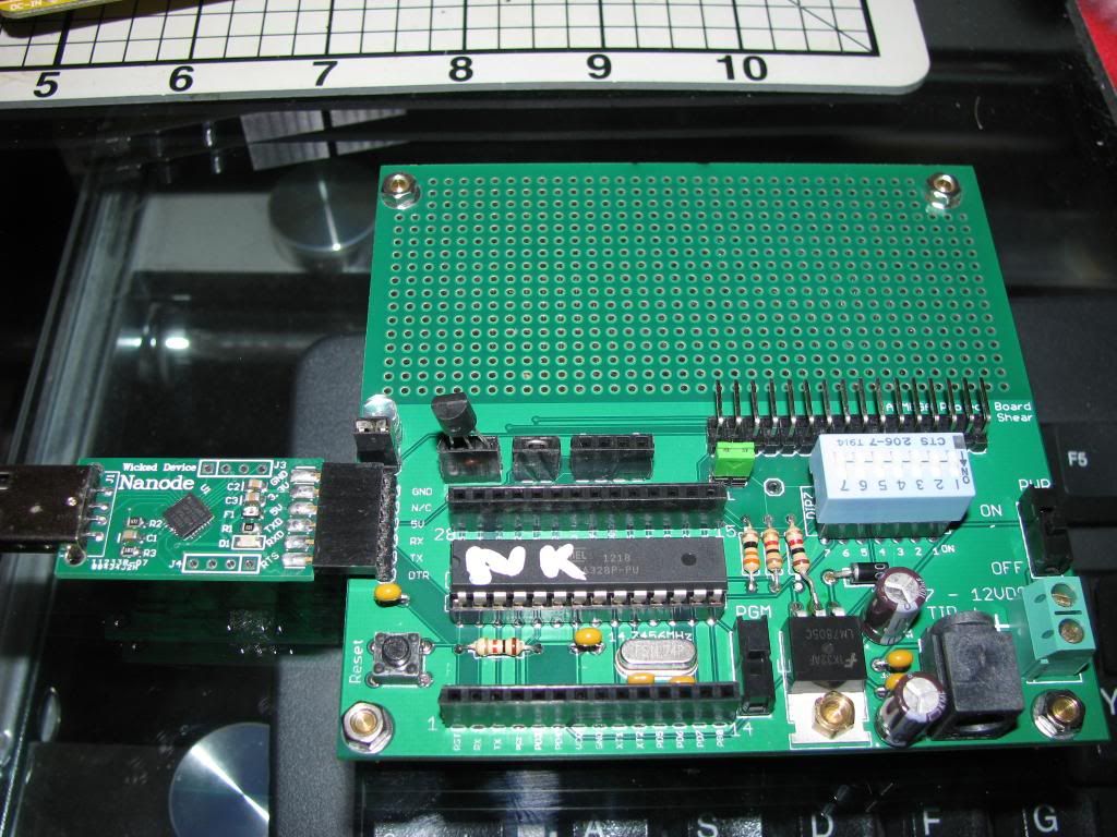
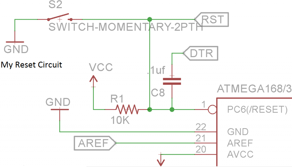
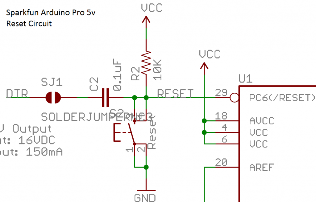
I was in the process of describing what I had done to test the autoreset portion of my board when it dawned on me... DUH... I have a 14.7456MHz crystal on the board... Arduino expects 16MHz. I'm sure that was my problem. The reason I thought I wasn't getting a reset was because I had loaded the blink program with my USB/Serial adapter to the Arduino chip on the Nanode to verify I could program it (Running Windows 8 now so I wasn't sure if it was the issue). I took that programmed chip and plugged it into my board and the LED was blinking but didn't stop when I tried to program it on my board. My guess the reset is so quick I just didn't notice. I'm going to either rebuild the Arduino bootloader (I'm pretty sure it's open source) to run at 14.7456MHz or built up another board with a 16MHz crystal and check again. My guess is it'll work. After all, I modeled my reset circuit after a proven working circuit as shown here: 1st Mine...
Then Sparkfun's Arduino Pro 5v
You can see between mine and Sparkfun's, they are pretty much identical. Rick |
|
December 16, 2012 by Rick_S
|
Well, Crystal speed was my problem... I modified the Arduino bootloader to support the 14.7456MHz crystal and it programs easily via both the Arduino IDE and command line. Now on to other the things. Paul, you mentioned whether a ZIF socket will fit in the board. It does, but it is snug in the holes. I have created an Eagle part for the micro with a ZIF socket outline with larger holes so that should work out... but a ZIF will fit as is w/o the backlight trimmer installed. Rick |
|
December 16, 2012 by Noter
|
What drill size does your new part for the micro use? My ZIF is a cheapo from China and the pins on it are .9 mm wide. |
|
December 16, 2012 by Rick_S
|
.04" (1.016mm). Mine are cheapo's from China too, but I think they are pretty similar to the 3M Textool sockets. |
|
December 19, 2012 by Rick_S
|
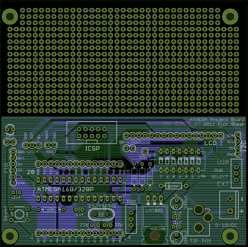
Well, Here is the 1st draft of DEV 3.0:
I changed the headers to arduino style to allow for shields, I moved everything around. I moved the mcu out from between the headers because if a ZIF is used it would stand too tall to get a shield on above it. I added a 3.3V supply. I don't know what to stick in the big empty space in the middle right now. This move cost me the prototype/breadboard area, but that can be done on another board or a prototype shield. Thoughts, concerns?? Rick |
|
December 22, 2012 by Rick_S
|
It seems many may have lost interest in this, which is no biggie as it has dragged out a long time However, I thought I'd upload my eagle files to my website in case anyone wanted to use them to suit their own needs. There are two files there:
To use these files, you should have the latest version of eagle software which you can get from their website and use for free with restrictions HERE. I hope someone will find these files of use. The only request I have is that if you do make changes that you keep this thread posted with them and make them available for other users to download as I have. I'm still open for any suggestions though. Rick |
|
December 22, 2012 by Noter
|
Just a busy time of year. I haven't given it a close look yet but since I know practically nothing about arduino shields I probably won't have much input anyway. And thanks for posting the eagle files, that will make it easier to have a close look. |
|
December 22, 2012 by Ralphxyz
|
Yeah Rick thanks a lot. I am certainly still very interested in this project!! Of course I have never gotten around to learning Eagle, hopefully this winter. I want to add Darryl's (sask55's) opto isolation USB circuit. I am just about finished assembling the circuit on the version 1 boards I have, what a time I have had putting that on the proto board area. I should have built it first on a breadboard to get the layout refined instead of trying to do it on the fly. Any way thanks again I definitely will put this to use. One might think why bother with the Nerdkit components once one progresses to a certain point. Well I for one have not progressed that far and I still like to revert back to the Nerdkit's projects for reality checks, that is to get me back to something that actually works when I get totally lost, there is usually something similar in the Nerdkits projects to things I am trying to do. Oh and thanks so much for the Arduino headers. I really like the shield concept it makes it so easy to use prebuilt circuits especially for prototype efforts. Ralph |
|
December 22, 2012 by Rick_S
|
Yeah Paul, I don't mess around much with the arduino processing language, but I do like the fact that there are all kinds of pre-build development boards and add-ons that use the "Shield" hardware layout. It opens a whole world of quick inexpensive prototyping options. And the headers can still be used the way my old ones could have been with jumpers to a breadboard. Rick |
|
December 22, 2012 by JKITSON
|
Rick Do you have any of the boards left from your last batch? If so would you part with a couple of them? Thanks Jim |
|
December 22, 2012 by Rick_S
|
I have some from both my 1st and 2nd batch. I don't know exactly what mail cost would be, but the boards cost me about $3.30 each. Rick |
|
December 23, 2012 by JKITSON
|
Rick If you can spare 3 of each let me know the total. My email is JKITSON@CANYONCOUNTRY.NET Thanks Jim |
|
December 23, 2012 by Pew446 |
This is a very neat project, I've been watching it for a while now, but I wanted to throw in my two cents about one of your comments, I noticed on the front page, under #4 in "What's the point?" So I think the reason the NerdKits team never thought about selling awesome boards like these, is because they want you to experience first hand how things connect and why they connect there, whereas on a circuit board everything is done for you. You can look at the traces and try to figure out where and why they go places, but it's sort of hard to see, and you can't modify it easily. These would be great for more advanced users who just want to test something before building a board and realizing they made a mistake somewhere. (Teehee) This is why I chose NerdKits over Arduino. It's much more hands on and you learn a lot more. :p |
|
December 24, 2012 by Rick_S
|
I'm sure the "learn as you build" mantra is at least one of the reason's behind the lack of an official board from the NK team. However, the amount of issues that arrive simply because someone has setup their base build incorrectly could easily be thwarted by a base build board, especially with the power supply and LCD wiring. The extras like the LED, DIP switch, Temp Sensor... could still be user built. Even just bare boards to help teach soldering where the end user ended up with a functional base setup could be of benefit to many. However, I'm not here trying to second guess their business model. I'm sure they've done quite well the way it is. My offerings here have been solely to promote discussion and ideas, and if someone wants to build off them... great. It's also been a way for me to show my thoughts for a board, and get input from other people for possible additions that I may not have thought of on my own. I see this discussion as a win/win for me and the community as a whole. Rick |
|
December 24, 2012 by Ralphxyz
|
For me the the "learn as you build" mantra is a lost cause. While I certainly have learned a lot usually when I have to get something working I used someone elses code which I might modify using the knowledge I have learned here in the Nerdkits forum. If I had a prebuilt circuit board it would have helped me learn a lot easier. Ralph |
|
December 24, 2012 by Noter
|
Yep, there is no substitute for programming knowledge/skill and the nerdkit and arduino are equivalent in that endeavor. When you learn to program you can program either one of them just fine. However, if your goal is to also learn electronics and digital circuits I think the nerdkit is better for that. Even those dreaded loose wires and lcd black bars are full of opportunity to fine tune your circuit building skills. With that said I do like the general purpose arduino boards like the nano with an onboard 328 and FT232. I have made them into ISP programmers and they work very good for that. Saved me the effort and expense of designing my own little board for a programmer. However the other day I shorted one of them and it died :-( but with the skills I have gained from working with the nerdkit I was able to find and replace a fried zener and it is working again :-). Not sure I could have done that if I had gone the arduino route. |
|
December 24, 2012 by JKITSON
|
Three years ago I started with the Nerdkits. It was and is fantastic. I took an idea and made it work on their breadboard. Now I wish to make this "project" permanent.... Thanks to Rick & his efforts in producing the boards I can now make mine. I feel the Nerdkits way of starting is the best. Once you have something that you want to use over & over, a etched circuit board is great.. Thanks Rick and all the Nerdkits supporters for making this for the rest of us.. Just my 2 cents worth.. Jim |
|
December 27, 2012 by Rick_S
|
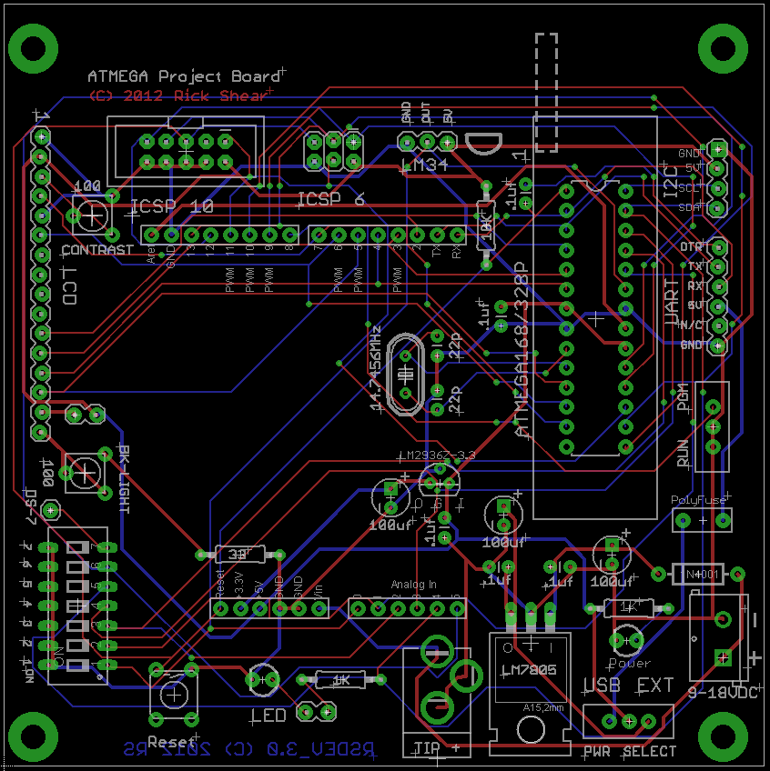
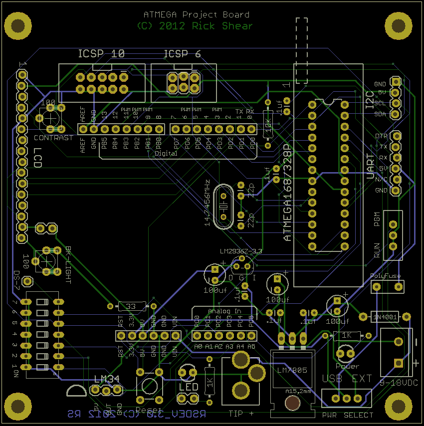
Well, I've had some time and have been working on my latest iteration of my development board. I've worked on two different versions. One version is more or less the same as the last image I posted which supports all the NK Guide projects. The second version removes the dip switch portion and adds a port expander with a connector to expand the I/O on board. On both versions, I modified the pads for the contrast/backlight pots to support two different style pin outs for them. I also, more clearly labeled the I/O connectors that support the arduino basic shields with the standard port names as well as the arduino number scheme. These shots were done with gerbview and are of the actual CAM output files that I would send to the board manufacturer. Here are screen shots of the two: First the original,
then the one with the port expander:
What do you think?? Dump the DIP and go with the expander, or keep the DIP and be able to build all Guide projects on the board? Any other thoughts, ideas, or concerns? Rick |
|
December 28, 2012 by Ralphxyz
|
Hi Rick, I figure I'd better start paying more attention to your board layout so I printed them out so that I could hold them in my hand and give a close look, I just don't see things (details) on the screen. Any way your .png files would not completely printout for me so I had to use Snagit to to get the whole board. Here are my comments/observations. As far as the dip switch or port expander I would not do either. One can always use a shield to use either. There are even breadboard shields so I do not think either is critical I would probable go for the dip switch just to keep the Nerdkit component theme. What I'd really like to see is Darryl's (sask55) USB Optoisolation, considering how much trouble I and others had with the yellow wire I really like the Optoisolation concept. Of course I am trying to add the Optoisolation circuit to one of your original boards and running into trouble (surprise surprise). I really think that would be a help. Now some questions: What are you doing with the 3.3 volt voltage regulator? How is it used? Were you going to add a transistor circuit to the left of the LM34? What are the INTA and INTB jumpers for? Would the PolyFuse be required? Why not have a four pin connection for the Nerdkit USB cable? You have a 6 pin UART connection so a four pin would duplicate some pins but a four pin connector seems cleaner for a Nerdkit component board. I still do not understand the TIP+ power connections? Are you the only one to use it? Plus I still do not like laying the voltage regulator down on the board what if I needed to add a heatsink? If you do the I2C port expander the 4.7K resistors should be jumpered (optional). Well that is my two cents, I am really looking forward to getting some of these boards. Ralph |
|
December 28, 2012 by Rick_S
|
As far as the dip switch or port expander I would not do either. One can always use a shield to use either. There are even breadboard shields so I do not think either is critical I would probable go for the dip switch just to keep the Nerdkit component theme. Point noted, but you could leave the components off and still use a shield if you preferred. I'm leaning toward the port expander to give an alternate LCD conection myself. I don't know how many people even use the dip switch once they've gone through the guide which they would most likely do on a breadboard anyway. I do find myself going back to the temp sensor and LED blink on occasion for testing things. What I'd really like to see is Darryl's (sask55) USB Optoisolation, considering how much trouble I and others had with the yellow wire I really like the Optoisolation concept. Of course I am trying to add the Optoisolation circuit to one of your original boards and running into trouble (surprise surprise). I really think that would be a help. I've never had the need for any type of optoisolation to program the chip. This is most likely to the fact that I have an older NK programming adapter that I use with a true serial port on my PC most of the time. When I use a USB to serial adapter it is an FTDI or Silabs CP2102 based adapter neither of which exibit the problems you've had. Now some questions: What are you doing with the 3.3 volt voltage regulator? How is it used? The arduino shield headers have a 3.3V pin that I figured if I were shooting for compatability I better power it. Were you going to add a transistor circuit to the left of the LM34? No, the diagram is just to show the orientation for the LM34 in the pads (or socket if installed). What are the INTA and INTB jumpers for? INTA and INTB are interrupts that are output from the MCP23017 to trigger an input on the microcontroller. I added jumpers so they could be connected or disconnected based on their use. If disconnected, the pins on the micro could be used for other tasks, plus you could jumper from them to an alternate pin if the default pins are in use. Would the PolyFuse be required? The PolyFuse is to help prevent USB overloading. In case of a short, the fuse would protect the USB. If a Polyfuse wasn't available, a jumper could be placed there instead, there would just be no protection then. Why not have a four pin connection for the Nerdkit USB cable? You have a 6 pin UART connection so a four pin would duplicate some pins but a four pin connector seems cleaner for a Nerdkit component board. You would be free to only use 4 of the 6 pins, however the 6 pin layout is a somewhat standardised. They are common in arduino's that have no FTDI232 built in. You can purchase FTDI boards that match this pinout on eBay and Sparkfun for a few dollars. Also, if one of those adapters are used, and the bootloader is programmed as arduino, the board will program automatically through that connector w/o having to flip the program switch. Here are a few links to compatible adapters LINK 1, LINK 2, Link 3 and many others. There are some wired differently though so if you were to get one, check the pin out 1st. I still do not understand the TIP+ power connections? Are you the only one to use it? On a Coaxial power connector, you have a TIP and a Ring for contact. The jack on my board is wired with the TIP (The hole in the coax plug) connected to VCC and the Ring (The outside of the coax plug) connected to GND. Plus I still do not like laying the voltage regulator down on the board what if I needed to add a heatsink? If you add a thermal transfer pad and screw, the board becomes a heatsink. I haven't experienced any problem. It would either have to be placed very near the edge or take up a lot more real estate to add a heatsink. Which could be done, I'm just not sure it's needed.?? If you do the I2C port expander the 4.7K resistors should be jumpered (optional). Good point, because if the expander weren't in use and someone wanted to use the SDA/SCL lines for input or some other data, the resistors may pose an issue. I'll add jumpers. Thanks for all the input, Hopefully I explained a bit of the thought process behind what I am doing. |
|
December 28, 2012 by Rick_S
|
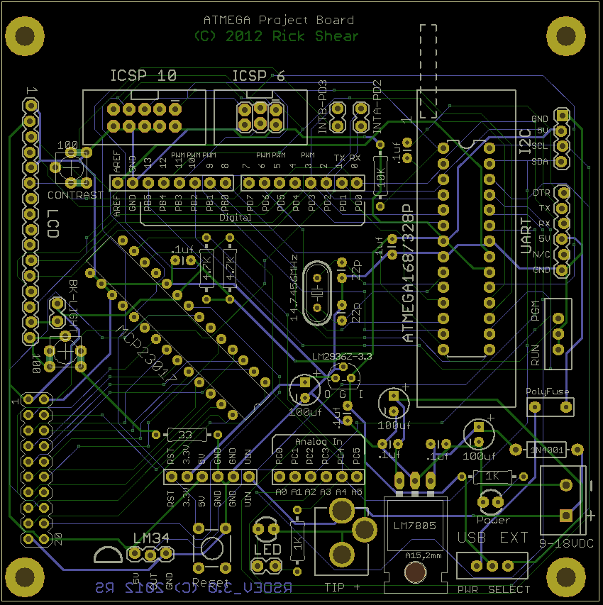
Here's a shot with the jumpers added (down by the temp sensor)
Rick |
|
December 28, 2012 by Ralphxyz
|
Thanks Rick, you always help to clear my muddled brain. Ralph |
|
December 28, 2012 by Rick_S
|
All our brains get muddled from time to time. Did you have any other questions / thoughts?? Rick |
|
December 29, 2012 by Ralphxyz
|
I sure wish I had the illustration of the traces on your first version. I have one more I am tempted to abandon my current build and go for a clean proto board it looks so much more logical to use your design. I had tried using my continuity sensor before I started assembling the Optoisolation circuit but had not detected the traces. Either I just picked the right/wrong pad to test or the lacquer prevented connection, oh well. Actually it would not be a big loss to go to another board. The current board does work the first one had problems with the LCD if I remember correctly anyway I have three boards and am really looking forward to your third version I really like the Arduino shield pinout. Ralph |
|
January 04, 2013 by Ralphxyz
|
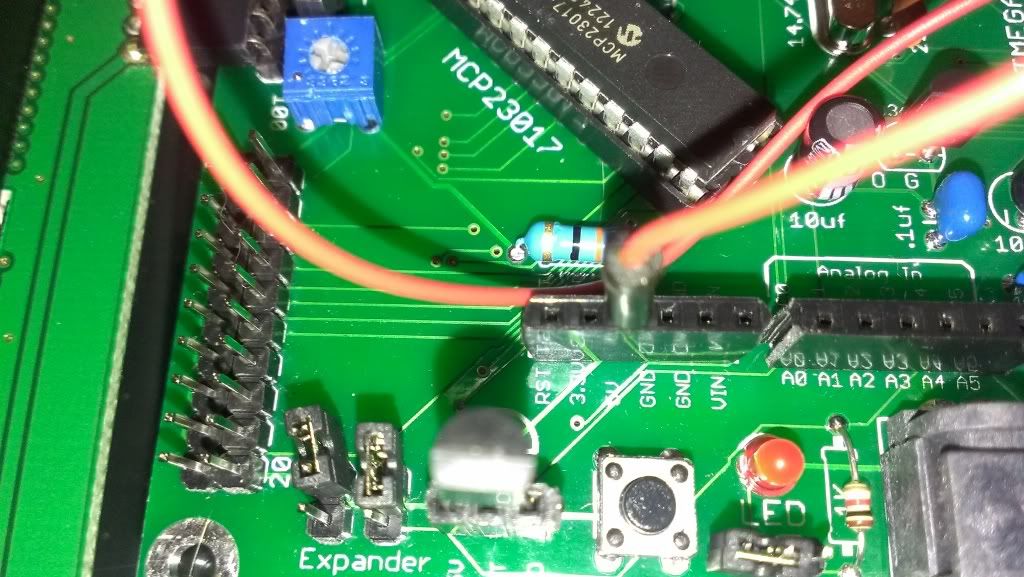
Well I finally got the version 1 board completed and dependable working (why do I always have problems:-) Thanks to Darryl's (Sask55) infinite patience I have the Optoisolation circuit working. The purpose of using the Optoisolation is to completely electrically isolate the Nerdkit and other circuits (motor controller/light controllers) from the computer USB. The fact that the yellow wire voltage zombie problem is solved is just an after fact. So here is my board:
You'll notice how in the last picture I had to use my Dremel to break the traces in the proto area. Hey Rick notice that jumper wire on the power switch? Once again I had to unsolder a component and when I resoldered the new component it didn't work. There was no power connection to the switch. This is the second time that removing and resoldering a component on your boards failed. I do not know if it is your fab doing the absolute minimum on the lands or maybe how you are specifying them but twice I have gotten stuck. But it is all working now, even using ISP in Atmel Studio 6 for programming, of course I can not use my Atmel AVRISP mkII programmer in Windows 8 for ISP programming from Atmel Studio 6, I have to use a Virtual XP computer (slow). I am really looking forward to getting some of the newest version of your Nerdkits Components PCb. Oh speaking of the newest version why don't you remove all of the Nerdkit components from your board and do a Nerdkit Shield? Also I like the I2C port expander (did you spec a cheaper one?) but would like to connect it to the LCD pinouts. You could have 6(12) jumpers to control how you were writing to the LCD. Well onward and upward, HI HO Happy New Year. Ralph |
|
January 04, 2013 by Rick_S
|
I'm glad that board is working for you... Kind of looks like a Frankenboard. I'd be a bit leery using varnished wires the way you did. I probably also would have cleaned the lacquer off the pads in the proto area there and taken advantage of the connecting traces instead of sawing it up As for the problem you are having when removing components, I haven't had that issue. I've removed and replaced the pot for contrast twice, the backlight pot once, and the power switch twice on the rev-2 board I have and had no issues with the board. All the pads stayed in place and everything kept doing what it is supposed to do. Maybe you are using too much heat too long, or something, I don't know. The traces are fairly large going from that power jack to the switch (24mil if I recall). Why do you keep having to remove the switch?? |
|
January 04, 2013 by Rick_S
|
Raplh Said: Oh speaking of the newest version why don't you remove all of the Nerdkit components from your board and do a Nerdkit Shield? Also I like the I2C port expander (did you spec a cheaper one?) but would like to connect it to the LCD pin outs. I got rid of the dipswitch, but I really want to keep the rest because they make great basic builds for testing purposes. I don't see doing a NK shield, as it really wouldn't add enough over my base board. The I2C expander is the cheaper readily available MCP23017. These can be purchased for a couple bucks or less each on eBay. I don't know about adding a dozen or so jumpers. I think just having the header connector there a cable could be made to connect to an LCD if you wanted instead of re-purposing the default NK LCD wiring. I'm probably going to be placing a board order in the next week or so, I want to get it in before Chinese new year which is the beginning of February. Everything in China shuts down during that time and things become very delayed for a month or so till they catch back up afterward. Rick |
|
January 04, 2013 by Rick_S
|
This is more what I had in mind for the prototype area on those 1st gen boards...
I thought of cleaning off the lacquer then using the pads with their connections similar to a breadboard layout. |
|
January 05, 2013 by Rick_S
|
OK, I think I have the final Vr 3.0 with Expander board done. I'm thinking of sending it off within the next couple days. Here's what it looks like.
Any other input before I send it out? Rick |
|
January 05, 2013 by oranger |
Hi All,
I've been following this thread for a while (stalking as my daughter would say) and am very interested. The breadboards are great for experimentation, but I now need more reliability in my connections as I deploy it for real work. For me, any variant of the boards you have talked about will work. I just need the basic features plus a prototyping area to make my interfaces to the outside world (three temperatures in, 1DI for IR remote, 1PWM out, 1SSR out, 1relay out). Thanks for all the work and discussion; you all have helped me learn a lot. Should you produce a batch of boards, I would be more than happy to put up some cash for your expenses and trouble. Bob |
|
January 05, 2013 by Rick_S
|
Here is a copy of the current Schematic. Note... I changed the contrast resistor back to VCC on one end and GND on the other. Every circuit I see out there has the contrast pot wired that way and it seems to work better as well based on my limited tests. I left the backlight pot wired in series.
Rick |
|
January 05, 2013 by Rick_S
|
Hello Bob, We must have posted about the same time. I'm not exactly sure how your current features are being wired into your breadboard, but assuming you are tying into any given pin on the mcu, as you said, any variation of the board I've done so far would have worked. If you were using a designed PCB, and were looking for good solid connections, you could solder wires directly into the board rather than installing headers as I have in my boards. Or, alternately, you could install the headers and make cables up to tie to your external components. As for money, I don't know if I'm to that point quite yet, and I don't think it would be right of me to try to make money here, via the NK forums. I do see the possibility of selling these boards (or some variations thereof) at some point in time, but I don't want to wear out my welcome here. I respect the NK guys business and don't want to appear to leach off their success (Unless of course they gave me their blessing Rick |
|
January 05, 2013 by Ralphxyz
|
Hi Rick, thanks for everything you have done. How did you clear the lacquer off the proto area? I used a 1/16" drill bit in my power screwdriver to break the lacquer away that worked sometimes. I didn't know that you had connected the proto board with traces until I had already placed some components and detected shorts in my pretesting that was why I had to grind the traces away. Now I have your illustrations of the traces so for my last board it should be clean. I like the lacquered wire you don't want to scrap it hard across sharp angles but I do not have any problems with it. I do not know how much interest the NK guys have left in the forum or supporting the NK for that matter. I assume they still answer their email but I really haven't heard much from them. Their input to the forum was for me so helpful. Now their Member Download is so dated, they literally have not updated it in years. It would be nice (and so easy) to have a commercial thread or just to make a page available in their store. But then comes "business" issues that have to be considered. They haven't seemed to want to do anything more for a couple of years, I had to really shame them in to having the Library which they have never really promoted. I think you could get away with a link in your post to your website if you wanted to do a sales option. It would be nice to do a consolidated sales page with other users projects like the LED arrays I'd love one of those smd arrays that esoderberg did. I like just the PCB then I could finally make up a reflow oven to solder it. Well hope I am wrong about the NK guys, I really miss their input. Ralph |
|
January 05, 2013 by Rick_S
|
I'd love one of those smd arrays that esoderberg did. Eric did a great job on that, but that type of soldering, not to mention part placement, is much more complicated than I want to get. I want my boards to be something a beginner or veteran alike can use. TSOP and SOIC packages aren't too bad and I could see utilizing those in some designs, but placing all those tiny LED's can be a pain. Plus, you'd almost need a soldermask template to get the solder down correctly. Then, even if you did reflow the one side, doing the second would either have to be hand done or done with a different temp solder so the 1st side didn't come undone. Yeah, the more I think about it, while I can marvel at his work, I'll stick with the thru hole LED's. I do not know how much interest the NK guys have left in the forum or supporting the NK for that matter. As for the NK Guys, specifically Mike and Humberto, I agree, we haven't seen much of them. I don't know if they got so wrapped up in their Circuit Lab site (I just checked and saw a post from Mike 12/27/12) or if they just feel this is running itself just fine. The last tutorial was the sous vide cooker and that was 7 Months ago. They haven't had a Newsletter (that was originally coming out Monthly) in 7 months as well. How did you clear the lacquer off the proto area? Very fine emery cloth (I think it was 1000 grit) on a board to keep it flat, then finished if off with VERY FINE steel wool. I just had to be careful not to remove copper, just the lacquer. Then I blew it all out, washed it with warm sudsy water with a clear water rinse and dried it thoroughly. One thing I definitely agree with you on is the unwillingness to move beyond this forum software. To my understanding, a lot of what this forum does is written by them, however, the Circuit lab forum software (Also I believe theirs) is much more robust. It supports sticky's, and many different tags like[b]bold[/b] [i]italics[/i] and others. Why they can't add these features to this forum, only they know. Why an editing function can't be added to allow a user to edit a recent post - a basic feature every other forum I'm part of has - is something they haven't added even though it's been begged and pleaded for. Anyway, RANT MODE OFF, I'm sure they have reason's. I also don't know why they don't update the links for current drivers, software, and compilers. I guess they just don't think about it. I do know though they are still very on top of fulfilling orders. I purchased a bunch of their switches (best price I could find) and some regulators, they packed and shipped it within a day. I had it within 3. Can't beat that. Rick |
|
January 05, 2013 by Rick_S
|
Well I just ordered 10 of the 3.0 rev with expander boards, and 10 of the LED Array Driver boards. I'll see how they work out in a few weeks. Hopefully they'll get them processed and on the slow boat from China before Chinese New Year. |
|
January 05, 2013 by Ralphxyz
|
Humberto said both forums use the the dreaded Markdown engine. They didn't that I know originate it. The "problem" with it is that everything has to be implemented on it, what we have here in this forum, is real bare bones. Things can be added to it but it takes skill and time. Most forum software is fully loaded and you just need to turn off what you do not want. Turning off things is a lot easier. I really like your led array also I want them both, greedy me!! I wonder how Eric did the two side soldering. Placing all of those smd leds must have been a pain. I wonder if the super glue trick would work but you would have to be exact in placing them. Well I have been wanting to do a reflow oven for a couple of years now so maybe this will get me closer to actually making one. Of course I cannot be satisfied with just getting a toaster oven at a yard sale I have to think solar power! I am interested in making a sun tracker and with that maybe I could make a movable Fresnel lens framework and cook a PCB. They are able to fry a steak with a Fresnel lens so why not a PCB. Ralph |
|
January 05, 2013 by Rick_S
|
I didn't order the LED Panel boards... Ran out of money. I'll probably get them in a month or so (With Chinese new year, probably more like in 2 to 3 Months). Once assembled, my LED matrix would be 1.5" x 7.2" consisting of 120 3mm LED's on a .300" pitch. Who knows, I may get the money earlier and be able to order them in a couple weeks. |
|
January 05, 2013 by Noter
|
Rick, RE: the voltage divider for the contrast pin. There are many examples on the web that connect the open side to 5v and I can't find good reason for it. If you run with much less than 5v then it may have to be connected to -5v to get an appropriate voltage on the pin but that's another story. Then there are several temperature compensating circuits that provide a somewhat dynamic voltage to the pin but that's another story too. All I can figure is that if a component has 3 leads most people feel they must all be connected to something. I made a few measurements and my nerdkit 4x20 lcd contrast pin draws 428uA with a blank display and 435uA when fully populated. With a voltage divider this small change has an even smaller effect on the contrast but either way I personally can't tell by looking one is better or different than the other. Is this what you refer to when you say it (the voltage divider) works better? Whatever the case, your circuit gives a good choice because it is a lot easier to cut a trace than to add a green wire. |
|
January 05, 2013 by Rick_S
|
Maybe I could add a jumper in a future version that way it could go either way... Just a thought, but then again, like you said, it's easy to cut a trace and most likely most people wouldn't care one way or the other. My reasoning was that virtually every contrast pot in manufactured boards I saw connect it that way. All of Sparkfun's are connected like that, and this LCD backpack by adafruit can easily be seen to be wired that way.
So, I'm not sure why either but who am I to buck consistency. I'll be a lemming in this case BTW, it is good to have you back in the forums, you were sorely missed when you took your hiatus. Rick |
|
January 05, 2013 by Noter
|
Thanks, glad to be back in the swing again. On the LED contrast - One more thing I observed was that the voltage drop across the contrast resistor was about .6v and it occurred to me that is about the same as the n-p junction drop across a diode. So I gave it a try and the diode works perfectly. With a diode instead of a resistor the current difference will not cause any measurable change in voltage and even though I can't tell by looking, this must be even better. Maybe if you get time you can try a diode and see if it works well with your setup too. |
|
January 07, 2013 by Ralphxyz
|
Ok here we go with my latest strange, aggravating problem. I have the version 1 board up and running, I am programming it using ISP on a virtual XP computer using ATmel Studio 6. Now here is the problem. I have to have the ISP plugged in and powered, in order for the program to run!! If I do not have the ISP plugged in and powered I get the dreaded two black bars on the LCD :-( Can you believe it, where in the world did this one come from. I thought I had seen this when I was setting up the Optoisolation but thought it was just the circumstance s of my messing around but now this. I will go back to using a breadboard in order to get some work done, geesch. Ralph |
|
January 07, 2013 by Rick_S
|
I wish we lived near each other, we could get together and get you a good dev board setup going. It seems like every board you work with starts giving problems or has some odd quirks. Maybe you have some static issues?? Hopefully your breadboard will behave. :) Rick |
|
January 07, 2013 by Ralphxyz
|
I "suspect" it has something to do with the ISP reset!! I also changed the program/run switch and now I am getting a 165K ohm connection between pin 14 and ground which jumps to 190K ohm with the ISP powered this with the switch in run mode. The reason I changed the switches (power/program-run) was because I had initially installed toggle switches but had not looked at the throw. Turned out I had them both backward so I had to throw the switch to turn the board on, same with the program/run switch they both were backwards. |
|
January 07, 2013 by Noter
|
Sounds like soldering issues. Sparkfun has a great tutorial section on soldering that I found very helpful. The other thing I do is always use plenty of flux and then clean with alcohol when the soldering is done. The liquid flux pens are pretty good but now I have a small bottle of liquid flux with a needle tip that deposits a small drop as needed and it works the best so far. |
|
January 07, 2013 by Ralphxyz
|
Nope definitely not a soldering issue. I thought the same thing but I am able to circle the pads with out contact to grn with my continuity probe. I have had problems with removing components on Rick's boards, possible I am using too much heat and melting the traces but unless they are really thin that is not likely and Rick said he has not had any problem with removing and re-soldering components. There is no continuity on the breadboard between pin 14 with the switch in program mode so there is definitely something happening on/in the PCB for me to show a resistance. A solder bridge would be the logical thing but unless I am seeing the same thing Rick reported when he had a shorting switch. My switch has a plastic body but maybe the solder wicked up and is making a short. I'll take the switch off again, nothing to loose. Ralph |
|
January 08, 2013 by Ralphxyz
|
Well here is my solution. I removed the switch and cleaned up the solder. Then I drilled out the lead pin to pin 14 hole enlarging it so that the switch pin does not make contact with the PCB trace. Then I soldered the center pin to the PCB trace to ground and ran a wire directly to pin 14 from the lead pin. Now the switch is isolated and everything works (for now). Ralph |
|
January 09, 2013 by Rick_S
|
Ralph, the traces from many of those pads are only .006" wide. Running a drill through the hole would most certainly destroy the trace connection to the pad. You should never have to run a drill through any hole on the PCB. I really don't know why you have been having problems with the board, I've built three of them and had no issues, other than the metal cased switch, with any of them. This is how I connect my board when I'm not using my true serial port on my PC. With this device, I can program the board by throwing the program switch just as a standard NK setup, or alternatively, if I program the arduino bootloader on the mcu, I can program it fully automatic w/o having to mess with the program switch (Very similar to ISP).
Rick |
|
January 09, 2013 by Ralphxyz
|
The reason I drilled out the hole was to isolate the pin. That was just to clear the problem of having to have my ISP plugged in and powered. I have ordered the suggested FTDI breakout board, for the next board. Of course the FTDI board has not been tested with the full release of Windows 8. As of now the version 1 board is working correctly. I still do not like my LCD arrangement, I could not just use the angle headers like you have as my proto area is populated so my LCD needs to be about a inch off the proto area. Of course I have your great I2C LCD board so I can also use that! Thanks again for all of the help, I really need it. Ralph |
|
January 09, 2013 by Noter
|
Rick, I notice your holes/pads for the LCD, I2C, and UART are not in a perfectly straight line. Wondering if that is on purpose or not? |
|
January 09, 2013 by Rick_S
|
Yes, it's an eagle footprint from the Sparkfun library. They purposefully shift every other pad a slight amount to 'lock' in the connector so it doesn't fall out when soldering. It works quite well actually. Rick |
|
January 09, 2013 by Ralphxyz
|
I wondered about that, kinda clever. Ralph |
|
January 16, 2013 by Ralphxyz
|
Well I got the FTDI USB adapter from Sparkfun and it works!! No problems at all with Windows 8. Plugged it in and Windows 8 recognized it immediately and assigned it COM 7, so it works as a com port, very nice painless install. Of course I still need to have my ISP plugged in and powered in order to run my program, what a pain. I have one more of Rick's version 1 Nerdkit component boards, I think I'll just take the time and assemble it especially as Rick has not had any of the problems I have. Or I am thinking of just doing a protoboard that way I could do a Arduino header pinout and be able to use Arduino shields. At least I can still use the command line to program my micros in Windows 8. I am having problems with ATmel Studio 6 in Windows 8 it is flakey at best. Of course there is no using the Nerdkits USB cable in Windows 8, which is a pain. Ralph |
|
January 16, 2013 by Rick_S
|
I figured the FTDI would work much better, they haven't failed me yet. Ralph, when youu put together the last board, try to build it like I did mine, except leave the diode that goes from the USB (the one between the chip I/O header and the LM34/AREF/I2C headers) out. You will then be providing power only from an external source. Don't try to add a contrast pot or parts that don't fit the footprint. Use the FTDI connector with a NK chip and program it via your normal method. Alternately, if a chip were programmed with the Arduino bootloader (a custom one to run at 14.7456MHz), you can change the avr109 in your makefiles to arduino, and you don't even have to throw a program switch anymore. I think you will have a lot more success this way. (Fingers crossed) Rick |
|
January 16, 2013 by Noter
|
I found the PL2303's don't last very long anyway. Maybe they are sensitive to static or something but I think you'll be happier with the FTDI adapter in the long run. And if you decide to run a 16mHz or 20mHz crystal the FTDI chip supports 250k baud. |
|
January 21, 2013 by Ralphxyz
|
Hey Rick, with the FTDI do I just let the power (USB 5v) float if I do not want to use it for power? If so then I only need GND, Pin2 (RXD), Pin3 (TXD) and Pin1 (RST) correct? I need to flip you order on the pinout in order to have the leds on the top for the Sparkfun FTDI module. Ralph |
|
January 21, 2013 by Rick_S
|
Yes, just let it float. I noticed also that they flip flopped the connector. Their old version had it the 180° opposite so the chip would have been on top when plugged in. Now it will be on the bottom. At least they didn't mess with the order of the pins. Are you building the 3rd board now?? Rick |
|
January 21, 2013 by Ralphxyz
|
Actually I just got finished building a Protostack PB-MC-AVR28 28 Pin AVR Full Size Development Board . Now I just have to add the FTDI header. The board has a 6 pin and 10 pin ISP header but since I use a ZIF socket I can not use the 6 pin header. I am having trouble with the 10 pin header but that is probable the cable I made up, I am sure their wiring is correct. That is some great documentation for a protoboard. Ralph |
|
January 22, 2013 by Rick_S
|
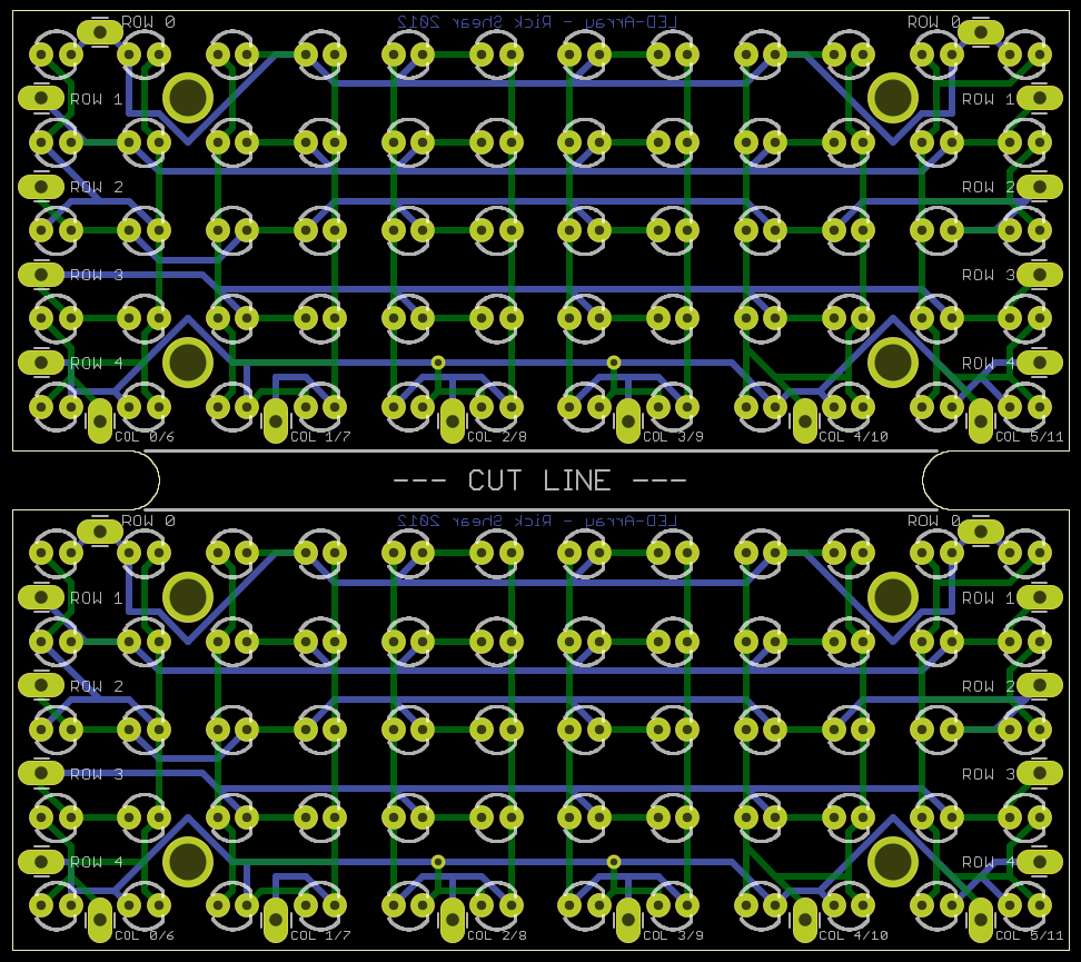
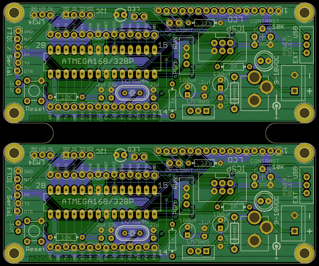
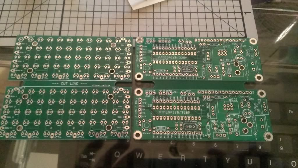
They definitely covered a lot in that pdf. Looks like they went out of their way to show as many different ways to mount various components they could. Not too bad of prices there either. I hope their board works out better for you. On another note, Sunday I ordered some of the LED Array panels and a condensed version of my basic board. I panelized them to fit two on a 10cm x 10cm board so I could effectively get 20 boards for the price of 10. I'll just have to figure out a way to cut them apart w/o damaging them. Here are the design's I sent out Sunday. 1st the LED Array Panel:
Then the Basic Dev Board:
I just hope they get fabricated and shipped before Feb 5th when everything shut's down for 2 weeks for the Chinese New Year holiday. Rick |
|
January 22, 2013 by Ralphxyz
|
I sure like the look of your boards. I have to learn how to use Eagle. I like the led array but of course I still have not gotten around to playing with your other LED array yet, I have a couple of them to get working. Ralph |
|
February 05, 2013 by Rick_S
|
New boards are in... I got my project board with the port expander and the LED-Array driver boards. I'll have to build them up this weekend if I have time.
I love new toys... Rick |
|
February 05, 2013 by Noter
|
Your boards look good. I'm going to have to give iteadstudio a try soon. They sure have good prices. |
|
February 06, 2013 by Rick_S
|
Thanks for the compliment, I've tried to pay attention to detail as much as possible. I can't wait to build one of each up this weekend to try them out. You should give it a go. I can't tell you how rewarding it is to see something you designed, laid out, and routed come to life in a real board. My only regret is that I wish there was a board fab house stateside that could even remotely compete with iTeadstudio. However, to get the boards made I just got, it would have cost me 6X as much or more, and not had to travel half way around the world to get here. I don't know if it's EPA regulations, cost of heavy metal/chemical disposal or recycling, higher wages, or a combination of all the above and more. It's just a regretful time in that respect. At least the folks I've dealt with at iTeadstudio have been honest, professional, and have resolved any issue I've had to my satisfaction. That and their fab pricing is the main reason I keep returning. Sorry to get a bit off topic there... Rick |
|
February 06, 2013 by Ralphxyz
|
Really in this day of automation with robots to do all of the dirty work you'd think there would be a cheap profitable fab house in US. Rick your boards look really great, lots of details. Does iTeadstudio have an access program where I could just get reprints of your boards or would I have to up load the files? Ralph |
|
February 06, 2013 by Noter
|
Rick, When you made your eagle files for the two-up basic dev board, is there an easy way to duplicate in eagle or do you just have to manually double everything in the schematic and then do the layout again too? |
|
February 06, 2013 by Rick_S
|
Ralph: No, as far as I know there is no provision on iTeadstudio to purchase another person's design. You'd have to get the files then upload them yourself. Paul: That was what I thought originaly, that I'd have to have two copies in the schematic. But then I learned a trick. After you have the board designed the way you want it, save everything and exit the project (I usually just close Eagle). Then create a folder in the project folder and copy just the *.brd file into it. This will be a rogue board only file that has no ties to the schematic. However, the original schematic and board are still tied. The advantage here is that you can edit the board file in the folder without effecting your "master" files. Open the board in eagle, then select all and copy. Move the copy where you want and now you have two copies of the original layout on one board. That's how I did the boards above. I'm eager to see how they turn out, but with the Chinese new year going on now, I don't know if they'll make it out of China. Their current status is processing at the HK Post office. I'm not sure if their post office shuts down for the whole period of the holiday or not... Rick |
|
February 06, 2013 by Ralphxyz
|
Rick would you send me exactly what you uploaded to iTeadstudio. Or do you want to sell me three of your Nerdkits components boards. Ralph |
|
February 06, 2013 by Rick_S
|
Ralph, I want to build one complete 1st to make sure it's 100% what I expect and that everything fits properly. I hope to do that this weekend. After that, we can talk. I'm assuming you are talking about the large board right?? Rick |
|
February 06, 2013 by Ralphxyz
|
Yeah, definitely. With all of the problems I have, I do not want a untested PCB. Ralph rhulslander gmail |
|
February 06, 2013 by Rick_S
|
I was using the freeware version of Eagle, but I now actually purchased a license for Eagle so now I can legitimately sell my designs if I choose. I got the lite version (It's only $69 +Tax) and has the same limitations as the freeware version but allows you to sell. I confirmed this with Cadsoft. I am looking forward to the next batch of boards so I can build the array complete. Should be fun. Rick |
|
February 06, 2013 by dvdsnyd |
This is really cool Rick! Those boards look really nice. I am excited to hear how they turn out once populated. How did you determine the trace width and spacing? Also, you're project board looks larger than what the freeware version allows, unless I am remembering incorrectly. What is the max board size you can make? Recently I have been using KiCad, but may jump ship and go to eagle, based on what I am seeing here. David |
|
February 06, 2013 by Rick_S
|
Max area for components is 80mm x 100 mm (3.15" x 3.94"). The board can be bigger though. My layout is at the limits for the components with the ICSP sockets at the 3.15" limit. You can have silkscreen and any non schematic additions beyond as you can see. |
|
February 07, 2013 by dvdsnyd |
I see. That is why I like KiCad. No board size limit. It definitely has some quirks however. One other question. Are you using load capacitors on your crystal? David |
|
February 08, 2013 by Rick_S
|
There are provisions on my board for them. I typically put 18pf to 22pf caps there depending on what the crystal manufacturer recommends (or sometimes depending on what I have on hand As for the board size, I really haven't run into much of a problem with space. I don't plan on designing a motherboard or anything really large and If I were to need more space, I'd have to break things up into two boards or go with SMD components (like I did on my led-array LED-Panels above). I've never even seen KiCad up and running so I really can't preach the benefits of Eagle over it, or the benefits of it over Eagle. I just know there is a wealth of information and tutorials for usage of eagle from many sources such as Sparkfun, Adafruit, and many private individuals. Plus the Adafruit and Sparkfun libraries are great freebies for providing good footprints for many common devices. Rick |
|
February 09, 2013 by Rick_S
|
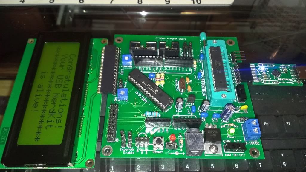
Well, I've built the Dev board and so far it seems to be passing the tests. 1st test: Load Nerdkit bootloader via 6 pin ICSP with USBASP Programmer.
2nd test: Load Initialload program via serial connection.
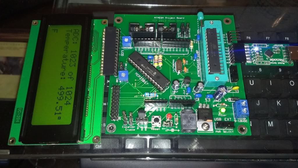
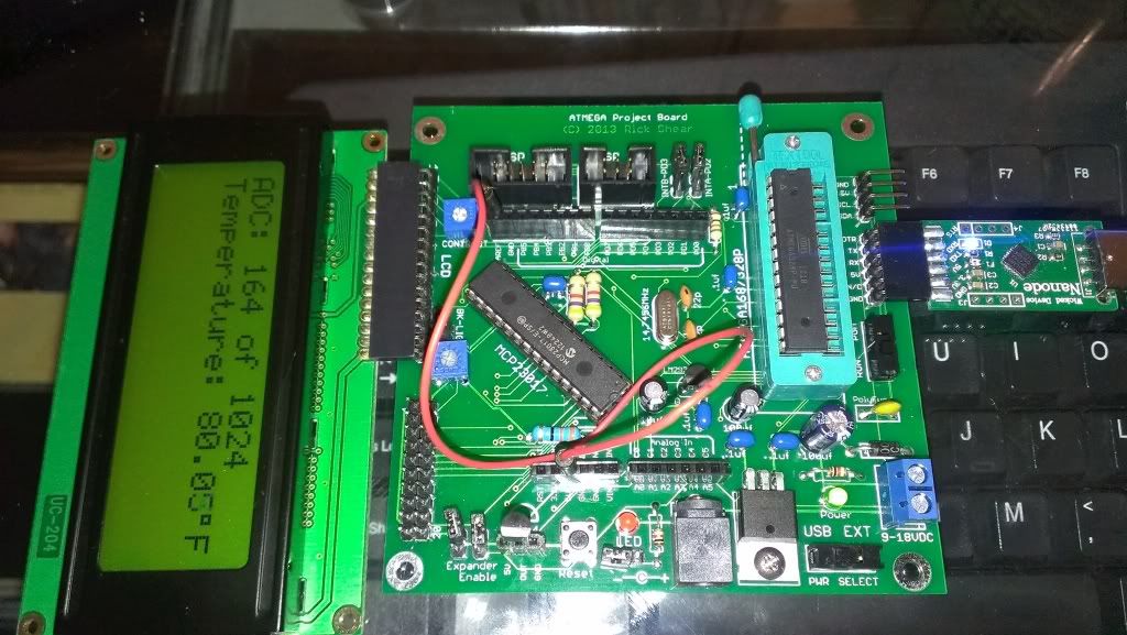
3rd test: Install LM34 and load Tempsensor program via serial connection.
At first I had a problem in that I couldn't get a temperature reading from this board. I plugged the programmed chip in one of my other boards and it worked fine. Then I realized I needed to tie AREF to 5V or program the ADC to use VCC. After I tied AREF to 5V, it worked as expected.
Well that's my progress so far. Rick |
|
February 09, 2013 by lnino 
|
Hi Rick, how could it be possible that I missed this thread. :-) In this thread everything is included what I have been looking for. You did again an excellent job. Congratulations. May you can share your eagle files of your lastest Project Board 2013 with the MCP23017? It is awesome that we use the same compoments. |
|
February 09, 2013 by dvdsnyd |
Looks good so far Rick! I think when I read your response about the size of the board you can have in Eagle the first time, I read it as 3.15x 2.94... 3 inches by 4 inches is actually a pretty good size board. Eagle, like you said, has so many tutorials. I may have to give it another shot. Keep us posted on your progress! Thanks, David |
|
February 12, 2013 by lnino
|
Hi Rick, some time has passed since my last pcb design. I think tooo long. After I thought some time about what I would like to have on my personal evalution board I think it would be a great project to design one in eagle. I have drawed right now the eagle library for MCP23016. So I can start now. I will keep you up with my progress. If someone is interested in the eagle library I can share it. |
|
February 19, 2013 by lnino
|
Hi guys, I have now finished designing my evaluation board. Here you can see an eagle3d view of the pcb. What do you think about it? I added a piezzo and a reed contact. I have also placed a female header (7 slots) for a 3x4 keypad matrix. Every Port of the ATMega168 is wired. I solved it completely drawing all the lines on the bottom side. I like the challenge. :-)
|
|
February 19, 2013 by Ralphxyz
|
Wow lnino, that graphic is great. Did you do that in Eagle? Do/can you work in three d view or is that just for illustration? Ralph |
|
February 19, 2013 by Rick_S
|
Looks like your voltage regulator and the jumpers by the heat sink tab are on top of each other. Of course if the regulator is stood up it wouldn't matter. Looks good! Rick |
|
February 19, 2013 by lnino
|
Thanks for the reply. @Ralph: I'm sad to say that you are not able to have a 3d view when you are drawing lines and making the schematics. But when you are done with doing the board you can run with the tool pov-ray for windows a rendering process which shows you how the board will look like. It's a really nice feature. @Rick: The view of the voltage regulator is a bug. As you can see on the picture the 7805er is a little bid to high and far away from the soldering pads. I think there went something wrong with the rendering, or I chose the wrong package in eagle. :-) I have now designed some addon boards for my evaluatin board to talk with the MCP23016 over I2C. First I made the 1Byte 8LED Portexpander Test. I am sure you can remember how hard we tried to get this working. I thought it would be also nice to control a 7 digit display with my MCP23016 over I2C. Let's have a look if it works, when I get the pcbs. What do you think about that?
|
|
February 19, 2013 by Ralphxyz
|
lnino, have you gotten input working with the MCP23016 or just output? Ralph |
|
February 19, 2013 by lnino
|
Hi Ralph, it has been designed to use only output on the MCP23016. But when I get my pcbs from factory, I will definatly give it another try. This will be my next upcomming project. I will design another addon board with some tactile switches to be ready to start the Input Project when the pcbs arrive. I will keep you up with my working progress on the MCP23016 Input. |
|
February 20, 2013 by Rick_S
|
Well, my latest toys have arrived. Now I just have to cut them in half. I'm thinking I could possibly set them up on my router table and just run them through to remove the center web.
Got a lot going on at home right now so probably won't get much play time for the next couple of weeks. Rick |
|
February 20, 2013 by lnino
|
Hey Rick, really nice boards. They look great. Are those pcbs also from your china store? It seams that they are making really good quality for that low price. |
|
February 20, 2013 by Rick_S
|
Yep, iTeadstudio. I've been quite pleased so far. |
|
February 28, 2013 by lnino
|
Hey guys. Today my pcbs arrived. For the case you are interested I have uploaded some photos. If it's okay for you Rick I will keep you up with my recents updates of my evaluation board in this thread. If I shall open a seperate thread with my pcb, just give me a note. It's definately no problem to do that. The pcbs are not that high quality like yours of china. I purchased them from Swizzerland. The pcbs were made in a day and arrived at my home within 3 days. Costs: 22 USD
|
|
February 28, 2013 by Rick_S
|
I don't think they look all that bad for a 1st run, especially for the price. It looks like they got the silkscreen off a bit in places, but that's just cosmetics. Hopefully they work out well for you. I've had several "learning" lessons in each version of the board I make. Whether it be part labeling, part placement, schematic/connection errors, or the placement of connectors, each board has taught me something new. I've come to think that good board design is 1 part circuit design, 1 part proper electrical layout, 1 part proper mechanical layout, and 1 part proper silkscreen/labeling. Each part is very important to making a fully functional, well designed board. With each version I've made, I get one step closer to having the board fulfill all those parts. Enjoy your new boards, and post some photo's of them built up and working. New toy time is always fun time!! Rick |
|
March 09, 2013 by lnino
|
I am back now with my finished pcb evaluation board. It looks really great, but I think I made some wiring mistakes because ISP Flashing and the Portexpander won't work. Now I have to check the wirings in eagle. There has to be a failure. But the display test was successful. :-) And the addon board looks quite cute. What do you think about it?
|
|
March 09, 2013 by Rick_S
|
Looks good. Don't fret the non-working parts... First generation boards often have some issues. Just look how many I've gone through. ;) |
Please log in to post a reply.
|
Did you know that Morse code is a compact way to transmit human-readable text over binary channels? Learn more...
|


Copyright © 2013 by NerdKits, L.L.C.

 .
.


 but at least it's working.