NEW: Learning electronics? Ask your questions on the new Electronics Questions & Answers site hosted by CircuitLab.
Everything Else » two black bars no matter switch position
|
November 07, 2012 by Ralphxyz 
|
Once again I am having to ask for help for a "simple" but often asked problem. I have been trying to use a PCB in place of using the breadboard like JimFrederickson has suggested. I also am trying to use the Mad Scientist business card. And I tried to use Rick's protoboard but I am getting two black bars no matter the switch position. I have gone through all of the threads that mention the two black bars (there are a lot). I know it is something simple and of course something I am not doing, or maybe am doing? Here are some pictures of my board do you see anything I am missing?
If you would like to see larger pictures: I sure hope someone spots something, this is the first rainy day I have had in a long time and being able to play er ah I mean work with my Nerdkit. Well I did get some time the other day but didn't run the generator 24 hours a day during the Super Storm, I can not imagine what will happen when we actually get hammered with a full blown Cat 2 or above Hurricane. The MCU is new from Nerdkits and works on the regular breadboard. Thanks again for the help. Ralph |
|---|---|
|
November 07, 2012 by dvdsnyd |
Hi Ralph! I am having a tough time making out what is going on in the pictures. But this gave me a bit of an idea that may or may not help you out... Maybe take your project and stick it in the drawer for a little bit and draw up the schematic from your notes and datasheets and then compare to your project. Sorry if you have already done something similar and that I am not more helpful. Good Luck David |
|
November 07, 2012 by Ralphxyz
|
Hi David, thanks for the reply. Essentially I "think" I have wired it up exactly the same as the Nerdkits breadboard. Ralph |
|
November 08, 2012 by Ralphxyz
|
Geesch, talk about missing details to help solve my problem. Using the Mad Scientist board as a ISP Target to do ISP programing (is that redundant) I can set the fuses but cannot program! I use Atmel Studio 6 and I can see (verify) the signature of the mcu and I can set the fuses (much improved in Studio 6) but I cannot program the mcu. Ralph |
|
November 08, 2012 by Ralphxyz
|
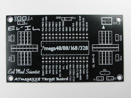
Here are pictures of an empty Mad Scientist business card
Ralph |
|
November 08, 2012 by Noter 
|
Have you checked continuity on all your connections with an ohm meter? Looks like a pin on the regulator is not soldered. Seems strange that you can set the fuses but not program. Electrically the circuit is identical for those functions and it's just a matter of a different data stream from the programmer. But fuse data is very small compared to program data. So if you had a poor connection it might be ok for a short burst setting fuses but then cause corrupt data on the larger program load. |
|
November 08, 2012 by Ralphxyz
|
Ok, I figured out my problem with the voltage regulator so I reinstalled the MCU and LCD header on the breadboard (and used a new voltage regulator). I get the same two black bars with the breadboard so I really suspect it is the LCD header I am trying to use. Of course that has nothing to do with not being able to do ISP programming. Here are some images of the frontside and backside of the breadboard:
I'd really like to have a neat LCD header and to know that no wiring of the mcu can get knocked loose. Ralph |
|
November 08, 2012 by JimFrederickson |
Hello Ralph, Sorry to hear/see that you are having problems with this. Probably now, any comments may not be of use to this specific problem since it seems things may have become more "catastrophic"! (Glad to hear your eye was spared! An Tantalum nearly took out mine one time, luckily just the forehead. Although later an "ice cude explosion" did cause me some grief...) I don't have any connections on the backside of the board I use. Things that I see, that I try to avoid are: 1 - I try to avoid putting components on the underside of things, which includes under chips, just because I like to be able to get the "big picture" as easily as possible. (I am old too, so sometimes I forget about things I don't see! :) ) 2 - I am a pretty big advocate of adhering to +/- conventions. It seems from what you have you are using some "red wire" as "general jumper/signal wire"? It works better, at least for me, to make sure that I ONLY USE red/black wiring for actual voltage/bus wiring. Then for jumper/signal wiring I always use some other color. Some of the things that I see as potential problems: 1 - It looks like something is not soldered on your programming switch. (Look at Picture ms2 top right quadrant. Maybe that is not important/necessary.) Also I can't tell from the picture if the programming switch is connected to the MCU, or not. 2 - Also in picture ms2 on the middle right hand side there may be a solder bridge that is not supposed to be there. It looks like the bridge could be between the VCC and GND bus. 3 - I can't tell from the picture if the 5 volt regulator pins are connected properly, but I can't see how the regulated power is getting to your bus? Nor can I see how the regulated power is getting to the VCC and GND that is already wired onto the card? (There does appear to be some red jumpers that may be doing that?) I didn't use any decoupling capacitors on the crystal. The only capacitor that I use is a 100 microfarad electrolytic for mostly power filtering. (In my playing around it have NEVER been a problem for me by not having the more common/recommended 3 capacitor filtering setup. NOTE: I do have a 7,500 microfarad capacitor off-board for buffering of the incoming power to the 5 volt regulator. Literally, using that setup I generally have like 15 seconds to unplug my AD Adapter and plug it back in if necessary.) I didn't include anything on my board that made it specific to connecting the LCD. That way I can use the same board for applications with the LCD or without the LCD. (Although I do take the power from pins 7 and 8 on my single inline female header that the LCD, or others things, do connect to.) That was intentional for me since these boards are just used for prototyping and playing. That way they are more flexible. (At least for me.) |
|
November 08, 2012 by JimFrederickson |
One more thing I was going to add, but now realize that I hadn't! Since my initial board setup is "non-lcd specific", I can very easily see if the Microcontroller is running, by loading in an LED flashing program, and just hooking up a could of extra components to the board. As for programming, I have had issues where the IDE seemed to be talking to the Microcontroller, but really wasn't. (At least to the extent that programming to would work.) I have found that the AVR ISP needs to be attached before power is applied to the Microcontroller. Then I usually read the Microcontroller Type before doing anything else. (Although I am not sure of the exact selection because I don't have any access right now since I am traveling, and that has become pretty much "autonomic" for me now.) I have only used the v5 IDE as well. Often, most of the time, I can leave the ISP plugged in while the Microcontroller is running without any issues and then reprogram without reconnecting anything. (If I don't use any of the pins on the Microcontroller that are necessary for programming, I don't exit the IDE, and I don't unplug the AVR ISP... Any of the above the conditions not being fulfilled can cause me an inability to program the Microcontroller.) |
|
November 09, 2012 by Ralphxyz
|
Ok, I got the breadboard to work. I had to replug the LCD pin 2 power line a couple of times and power off the mcu and it started working!! So my LCD header does work!! It's interesting that if I unplug the LCD pin 2 power line while the display is working and replug, that I get the two black lines and no longer the display!! I have to power down the mcu in order to restore the display. So just wiggling wires will not fix the display if it is showing the two black bars so I have to wiggle wires and power down then power up to see if my wiggling has any effect. I can not find any bridges or shorts with my continuity tester (speaking of which, does anyone have a good circuit for a continuity tester? The multi meter testers I use are not 100% reliable they sometimes are not sensitive even to touching the probes together). This wire wiggling is exactly why, like Jim, I want to have a dependable working solid base that I know I can count on working every time I turn it on and not have to worry about moving it around. Good eye Jim, man it is good to have a extra set of eyes. The programing switch is a DPST so the unsoldered pin is not used but I had neglected to bend the pin over to contact pin 14 on the mcu. This doesn't help the two black bar problem as without the switch pin 14 is floating which is what it does in RUN mode. But definitely it is needed for USB programing. I did not use any red wire for signal wiring just as power line jumpers. I only have a resistor on the bottom of the PCB plus jumper wires for +/-. The PCB does not have provisions for a reset switch or pull-up resistor. I kinda like Atmel Studio 6, especially compared to Studio 4! Especially for fuse setting. Of course now my Windows computer has completely died it now refuses to even boot, so I no longer have Windows or Ubuntu. Well I do have XP in a Parallels virtual machine on my Mac mini but I do not have Studio 6 installed on it. I sure made a mistake in thinking I could "build" a high end Windows computer on my own. I used a top of the line Intel quad processor and 8 gigs of memory with 3 500 gig harddrives, that was four years ago and I have had to replace the motherboard four times, now it has died once again. I have a new HP computer due next week. But then I'll have to deal with Windows 8. Ralph |
|
November 09, 2012 by Noter
|
I've never use Atmel Studio, is it better than avrdude for setting fuses? |
|
November 09, 2012 by JimFrederickson |
Part of the issue with the LCD and not just coming online, after a problem, by "wiggling the wires", is that it is intelligent and has a "software reset protocol". If the "software reset protocol" is not followed after powering it up then I don't think the LCD Controller will communicate at all to the Microcontroller. The "2 black lines" seems to be a "default state". Since the Datasheet is somewhat sparse it is hard to tell exactly what that means. I "THINK" that is means that the onboard LCD Controller is powered up and working properly, but I wouldn't be at all surprised to learn that it ONLY MEANS that the LCD and the board has been powered up. (Regardless of whether the LCD Controller is actually working or not!) So that doesn't surprise me. I did send the Evil Mad Scientist people an Email regarding a few things that I think would make the board better. They were VERY CORDIAL, but I didn't get the impression they were going to make any changes. (A reset switch, adding a solder pattern for a 78xx style power regulator, and a power LED were three of them!) I opted not to have a reset switch. I have a power button, and that does it for me. As I noted, I mostly leave the AVR ISP Programmer plugged in all of the time when I am working on code. Reading the program, or reprogramming will both cause resets! As far as "building a computer", that often can work well! The most important points for "longevity" is to make sure that you have good ventilation, and a good power supply. (Also, if you have any power issues where you are, a good UPS on the outside is important as well!) Through the years, I have found it much more "cost effective" to stay in the "mid-range" of "performance"! "Cost vs Performance is "non-linear" and "costs tend to rise with a much higher multiple than performance after about the "mid-range". I have had good luck with HP's in the past. (Although it really have been decades since I have personally purchased a "Manufacturer built desktop", I have purchased numerous laptops.) I also, firmly believe, that Computers tend to "fail when you want them to work the most"! My little HP Laptop FAILED, about 4 days before my current trip. (I am not complaining, at it was about 7yrs old and was beginning to have some issues but I didn't think it was quite so close to the end either!) So I had to scramble to get a new laptop to have some connectivity while I was "out and about"! Hopefully, when you get your NEW COMPUTER you will be off and running again AVR-wise! |
|
November 09, 2012 by Noter
|
Instead of relying on the Mad Scientist folks to change their design you could layout a custom board in eagle and have it manufactured quite reasonably. I've been using OSHpark and they are $5/sq in for 3 boards, shipping included. So a little board like this would be around $35 for 3 of them or $11.66 each and you get exactly what you want. If you're not already fluent in eagle this board would be a good place to start. |
|
November 09, 2012 by JimFrederickson |
There are other options besides this particular board. I had brought it up on these forums originally, because it is the ONLY board that I found that was general purpose enough and still quite cheap that seems to be well made and thought out. (Some people may have found other boards that suite them better, but for me this one works quite well.) Admittedly you cannot solder and de-solder for as long as you own the board, like the good'ole 1/8" I think, boards of yore without the pads delaminating. In defense though, are there really any boards outside the commercial/industrial sector that you can do that with anymore that anyone here would be willing to afford? The board is small, but not so small where soldering for any ordinary person is an huge issue, it is organized well, is has the majority of what is necessary for the core of a Microcontroller Project, and EVERYTHING is very clearly, nicely, and accurately labeled... Anyone here, can purchase one, and I find having the "core Microcontroller Hardware" setup more-or-less permanently and "breadboarding off of that" to be very helpful so that the "core Microcontroller Hardware" does not need to be continuously verified. (loose jumpers, missing jumpers, bad connections points on the breadboard, etc...) How much time have people here wasted tracking down problems that really had nothing to do with their "project", but was simply something that had gone wrong in the connections with their "core Microcontroller Hardware"... I haven't, by any means, been "relying on the Evil Mad Scientists to change their design". I purchased their board, multiples, and trotted on off down the road of Microcontroller Projects with it in hand. I gave my comments to them that I thought may be helpful to other people as well in a generalized sense. Similar to comments I gave to Hyundai in 1986 for not backing their CRT Warranty! "I will never purchase another Hyundai Product again for as long as I live"! (Albeit, not as generalized but exactly the same sentiment as well as reason as with Maxwell a few years before...) While the cost of "custom boards" has gone down considerably, at $3 per board, $2.75 if you purchase 10 or more (25 for instance :) ), it is still MUCH CHEAPER. (And I think that most people here are not quite ready to produce custom boards, everyone here though has already proven they can order online! :) ) For custom boards, I like supporting Sparkfun. (A company whose philosophy is based on selling "open hardware" as much as possible. In fact I think EVERY board they produce they have the Eagle Schematics for online!) I like here for the forums, and I do still purchase things from Nerdkits as well. It, both the company and those here, seem to be a great group. |
|
November 09, 2012 by Noter
|
Could you tell us about some of those other options? Maybe one of those would work better for Ralph? |
|
November 10, 2012 by Rick_S 
|
Hi Ralph, I wish I could help more, but I can't really quite see what's going on in your photo's. That's something that would be a bit easier to follow if it were right in front of me. I was kind of suspect of the black blob at the start of the header for the LCD, but it seems you may have somewhat worked your problem out. I was wondering what issue you had with the board I sent? I was hoping that would solve a lot of these problems you are having. I'm still contemplating a different or updated version. I just haven't been messing around with my electronics side of things much as of late. On another note, how's the cleanup/power situation going? Every time storm coverage pops up on our news, I can't help but think of you, because you are the only point of reference I have for the NYC area. Rick |
|
November 10, 2012 by Ralphxyz
|
Hi Rick, I'll have to see if I can find the thread we were talking about your development board and the problem I was having. Yeah your boards are exactly what I need maybe I will try another one, you sent me three. It looks like I had your board working and then changed the LCD header and it stopped working. Now these boards were from your first run I believe (NKDEV_1.0 (C) RS)
Do you remember what I need to do to work around those errors? Ralph |
|
November 10, 2012 by Noter
|
Hey Rick, I just looked at your dev board that you designed - nice job! I like it. Paul |
|
November 11, 2012 by Rick_S
|
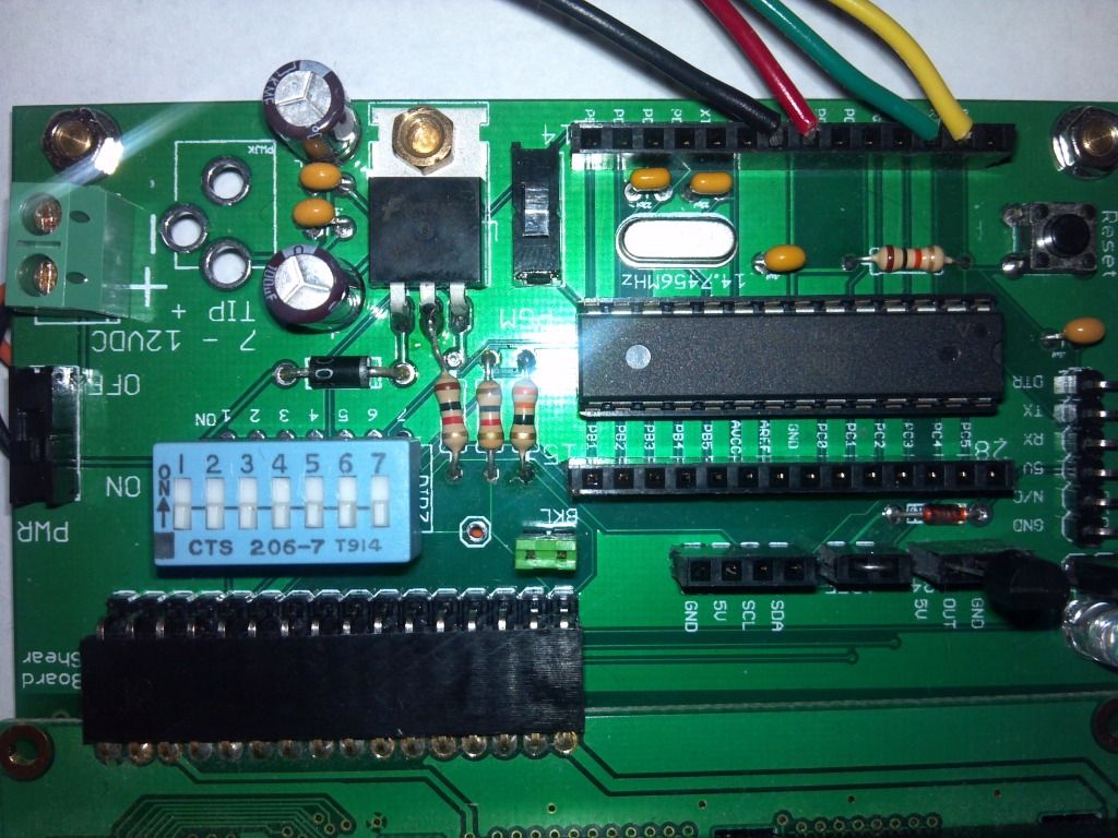
Thanks for the compliment Paul. I initially wanted to try to build a platform for the NK Guide. Other than the issues Ralph mentioned, it was pretty successful. The board provides the ability to do all the guide projects without most of the worry about wiring on the breadboard. There is a built in LED for the blink project, a socket for the dip switches, breakout for the LCD, Temp sensor, etc... all connected to the micro as the guide shows. I then added a prototype area (That I forgot to keep the lacquer off) and headers in case people wanted to jumper to a breadboard. I have a newer revision I just haven't had made yet that fixes the problems. Ralph, The USB power issue is only a problem if you try to use power from a USB/Serial adapter like a ft232 board. If you wire the NK adapter directly to the pins, it should work the same as on a breadboard, you would just not want external power applied in that circumstance. As for the contrast resistor, that is an easy fix. Just keep the regulator end of the resistor out of it's through hole and solder it to a leg of the regulator as shown in this photo.
That fixes that and makes the board functional. I use my board often and have had no problems whatsoever with it. Rick |
|
November 11, 2012 by Rick_S
|
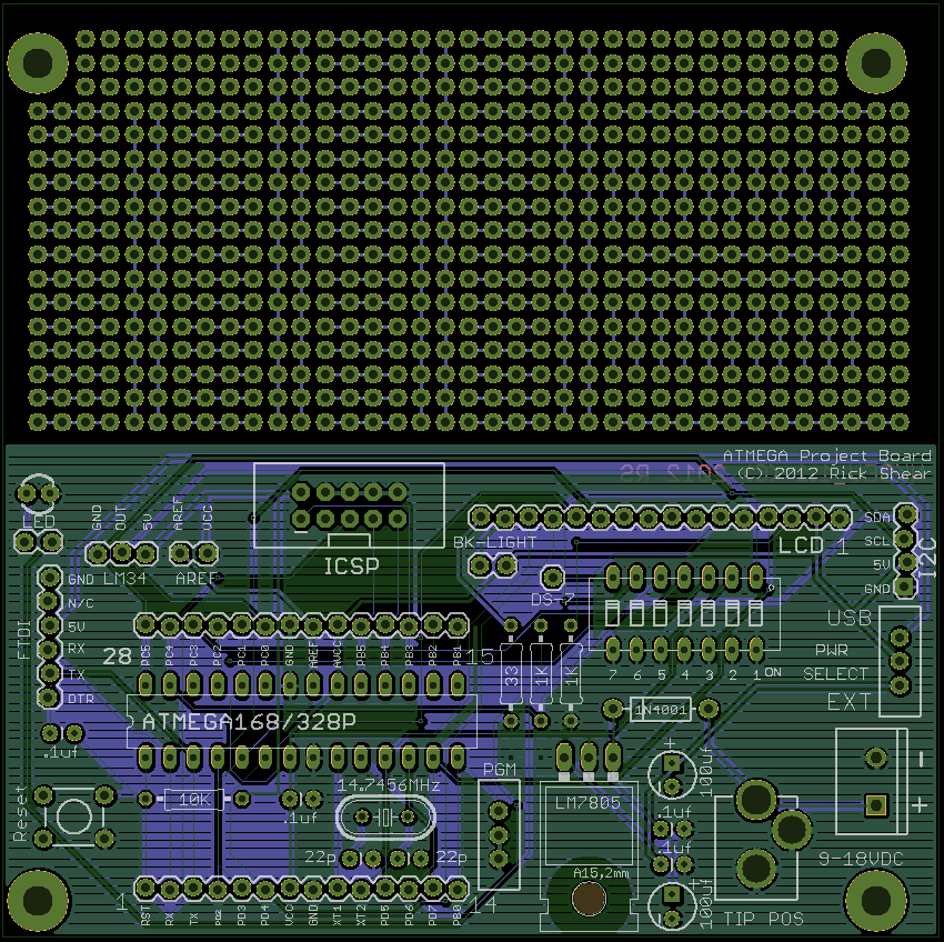
In case anyone else is unsure, this was the last revision I was working on. It fixes the issues I had as well as provides for an ICSP programming header.
Anyone have any suggestions for improvement?? If not, maybe I'll order up a set. Rick |
|
November 11, 2012 by Rick_S
|
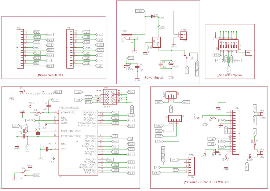
Here's the schematic:
|
|
November 11, 2012 by Noter
|
What do you think about a variable resistor for the contrast and brightness instead of fixed resistors? That would make changing displays (type or mfg) easy because most need different ohm values. And it would provide adjustment on the brightness of the back light. Maybe the kind with a screw on top like this.
Also, maybe I should know, but what are the three large holes for where the label says TIP POS? Paul |
|
November 11, 2012 by Noter
|
I just saw the schematic, did you use eagle? If so, how do you make those little tags for the signal lines? Paul |
|
November 11, 2012 by Rick_S
|
The vacant holes were for a Tip Positive coax power jack. I just never mounted one. I could add a trimmer pot or two, but I was trying to keep the 'non-NerdKit' parts to a minimum especially since it was meant to be built with NK components per their schematic. As for the schematic, I did use eagle. The signal lines are tagged with the label function. Rick |
|
November 11, 2012 by Ralphxyz
|
For one thing it is graphical so you see what you are doing. You can either select each individual step or just enter single hex value (which didn't work well in prior versions). One of these days I hope someone will do an Nerdkits Community Library article on how to use avrdude to set fuses and a step by step instruction on using the command line in general. Like using avrdude for ISP programming I have never seen a concise listing of steps or commands. Ralph |
|
November 11, 2012 by Noter
|
Ralph, avrdude is pretty well documented. I think the documentation is in the avrdude install directory on your PC but usually it's quicker for me to find it online - avrdude user guide. It's good for command line (makefile use) and terminal mode but doesn't get very deep into describing the configuration file. I occasionally use terminal mode when debugging my isp programmer or if I just want to view fuse values but not much really. Thanks Rick for the info. I'll try out the label command soon because some of my schematics are pretty busy with lines going everywhere. Paul |
|
November 12, 2012 by Rick_S
|
That was why I started using them. It became difficult to see what was going where. The labels also help to segregate sections better. |
|
November 12, 2012 by JimFrederickson |
For me, I am with Ralph on this one. I had started with the Atmel Studio many years ago, because that was really the ONLY practical way for a long time to program AVR's. (The Command Line tools were a bit too cumbersome and annoying to use.) The tools that Nerdkits has employed are nice though. (I do all of the programming through those now.) I like them ALOT. For now giving up the Graphical Control of the Fuses is not something I am prepared to do. I find it especially nice when switching back and forth between different MCU's. There is ALOT less chance of me making a mistake. Ultimately, I will have to switch simply because I have pretty much "given up on Windows". (I suppose it may be possible to run the Atmel Software in WINE on Ubuntu, but just for the fuses? Probably not, but then again?) MOST of my computers are running Ubuntu now. Compiling for the AVR on Ubuntu works well. I haven't done anything on the "chip programming side" though... |
|
November 12, 2012 by Noter
|
I use an online fuse calculator to get values for the features I want and then put it all in my make file. I have only a couple of configurations on the 328, one for an external crystal and one for the internal 8mhz oscillator. The 168 fuses are still in the make file but I never use 168's anymore. Then the fuse values are set automatically depending on which MCU and F_CPU combination I set earlier in the make file. Then I have an option in the make file to only set the fuses which I typically will only do once with new chips. Using the command "make fuse" will set the fuses. "make verify" will complete successfully only if all the fuses match otherwise it fails on the 1st one that is different. If I really want to know current fuse values I will run avrdude in terminal mode and use the dump command. This is the most convenient way I have found to set fuses with avrdude. |
|
November 13, 2012 by Ralphxyz
|
Wow thanks Paul, I am sure I would eventually figured out how to set fuses by reading the avrdude user manual which I did go through a couple of years ago but didn't really comprehend much. Well I didn't have a need at the time and was mostly just curious so I didn't try to apply what I was reading. The user guide is a great document. Just your Make file above with a little explanations would make a great Nerdkits Community Library article. Seeing what you are doing makes me more curious about what can be done and how to do it so thanks again. Hey Rick re:
I am going to start a new thread dedicated to suggestions for the Nerdkits projects board. I have a couple of ideas that if I was doing it I might incorporate Ralph |
|
January 04, 2013 by Ralphxyz
|
RE: Not being able to do ISP (programming) using Atmel Studio 6 with my AVRISPmkII programmer. The answer was to speed up the programmer in Studio not to slow it down!! So ISP finally works (I think, I have unsuccessfully played around with ISP for two years now never getting it to work until now. I always set it at the slowest settings because of the warning "The ISP clock frequency must be lower than 1/4 of frequency the device is operating on". Oh well live and learn. Now I still am fighting with the two blackbars a real pain. Ralph |
|
February 08, 2013 by Ralphxyz
|
This is sooooo irritating. Now three of my different breadboard and PCBs that were working fine two days ago are stuck with the two black bars, they no longer run a program. Of course now my Mad Scientist PCB which I noted above was getting the two black bars is now working correctly. Well maybe the Mad Scientist board did work before only I was having problems with Atmel Studio and ISP programming because I had the programming clock set to slow. I made some additions to one of my PCBs so that might be the answer for that board but I cannot detect any shorts or problems besides being stuck with two black bars. The mcus program but do not run the program (LED Blink and tempsensor). I know others have had problems with getting the two black bars but for me they persist, I have never found "the solution". I'll make up a new PCB (wish I had one of your new ones Rick) I still have one of Rick's original Nerdkits Component boards and another Mad Scientist business card and also one of the Protostack boards. Ralph |
|
February 08, 2013 by Noter
|
If you can successfully download a program to the chip, the black bars usually mean there is something wrong with the program and it has failed for whatever reason to properly initialize and clear the LCD. If you go back and download the nerdkits initialload program and it still doesn't work then either the download wasn't really successful, or you have a wiring issue with the lcd, the program switch, or the reset pin. I suppose your chip could be bad too but that is unlikely. |
|
February 08, 2013 by Noter
|
One more thought, the program mode switch is only applicable if you are using the bootloader. If you use your isp programmer to load a program then probably you have wiped the bootload off the chip. |
|
February 08, 2013 by Ralphxyz
|
Thanks again Paul, I keep a original Nerdkits mcu for testing so I know I always have a good mcu. I usually go back to initialload in fact before I load a new program I always load initialload to make sure everything is running. I have programmed the mcu on a black bar board and moved the mcu to the Mad Scientist board where it runs so the chip is getting programmed correctly! I can successfully load the mcu with my programmers or the bootloader but all that works today is the Mad Scientist board two days ago it was working on Rick's component board, the protostack board (I have not touched Rick's board, the protoboard I added some headers, I can not detect any faults or shorts), and a extended breadboard. I didn't test the protostack board immediately before adding the headers but it was running fine the day before. Well we are heading into some messy winter weather so I'll have some time on my hands to put together another board. At the moment I only have one PCB board working of course I can always throw together another breadboard. It is strange that a extended breadboard that I have used for at least a year stopped working yesterday also. Ralph |
Please log in to post a reply.
|
Did you know that multiple MOSFETs can be used in parallel to switch bigger currents on and off? Learn more...
|


Copyright © 2013 by NerdKits, L.L.C.


