NEW: Learning electronics? Ask your questions on the new Electronics Questions & Answers site hosted by CircuitLab.
Project Help and Ideas » Optocouplers
|
January 17, 2012 by sask55 |
I have a general question about when it would be advisable to use of optocouplers in a circuit design. I have incorporated optocouplers in several circuits in the past to protect the parallel or serial ports of the PC. I wanted to protect the PC from possible stray VMF that may have originated from high voltage motor controls and relay coils that I was controlling from the PC. In most cases I made those circuits before I discovered the Nerdkit and how useful a micro can be for that type of control from a PC. I have noticed that virtually all commercially available, and I assume professionally designed, stepper motor control units stipulate that they have optocoupler protection incorporated in the design. This feature is usually stated as protection for the computer and peripheral equipment not for the components of the controller itself. Larger stepper motor control circuit make use of two voltage supplies. A 5 volt low current supply used to power the logic and control components and a higher 12V to 36V supply used to energise the motor coils with much larger current. The very nature of the motor coils with there reactively low resistance with considerable inductance will lead to back EMF and current/voltage surges within the high voltage parts of the circuits. It seams wise, if not essential, to isolate most of the more sensitive components from this source of potential noisy and potentially damaging spikes. What I am attempting to design is a three axis CNC control unit using AtMega micros between a PC and the stepper motor control chips. The stepper control chips will handle all the high voltage higher current power and also use a separate 5V power source for thier logic circuitry. The Micro need only supply 5 V low current control signals and read the state of various 5V output pins on the stepper motor control chips. My plan is to use 3 mcu chips a master and two slaves, one for each of the three axes. Each mcu will be control and monitor a separate stepper control chip as well as monitor the readings returned from the digital callipers and the limit switches associated with that axis. The master mcu will handle communications via the uart with a PC as well as print information to the LCD screen. If I am able to handle all the time sensitive communications in software my hope is that the PC will send movement control commands to each stepper motor and the micros will return position and other information to the PC. I will also require control of the 24V power supply to the stepper chips to enable me to accomplish a proper start-up and shot down sequences for those chips. I am having difficulty deciding on what level of otocouplers protection I should include in the design. The simplest and most risky option – none at all, just build the circuit and hope all goes well. Considering most bought controls incorporate some level of isolation this option seams unwise to me. I do not know If the USB serial cable from Nerdkits offers any level of projection to the computer. I could incorporate a couple of optocouples at the UART pins on the master mcu and protect the computers USB port. I don’t know if that is a sensible option. I could use a opticoupler in each and every connection both input and output between the mcu’s and the control chips. That option should insure that the micros, callipers and computer are protected from whatever is going on in the control chips. That would require a lot of extra components and there is no indication that it would be required on any of the data sheets. Seams like too much to me. Then there is the 24V control, I am leaning towards a relay setup but also considering a large MOSFET. In theory a 240 watt supply could push up to 10 amps if there were a number of motor phases using high current. Should I consider isolating this 24V switching device from the mcu with a opocoupler? If anyone has any experience with what level of protection is adequate or what is typically done in the industry I would appreciate any comments or suggestions. Darryl |
|---|---|
|
January 17, 2012 by hevans (NerdKits Staff) 
|
Hi sask55, I have no experience in industry in anything like what you are describing, so I'm not at all an expert here. Seems to me your stepper motor control chips aught to do most of the safety things you need in terms of protecting your chip. As far as isolating your computer electrically from your circuit, that is probably a good idea. At the end of the day, a stray voltage spike or wiring mistake that takes out a $5 chip is not a big deal, but a several hundred dollar computer is a much different story. Humberto |
|
January 17, 2012 by hevans (NerdKits Staff)
|
Hi sask55, I have no experience in industry in anything like what you are describing, so I'm not at all an expert here. Seems to me your stepper motor control chips aught to do most of the safety things you need in terms of protecting your chip. As far as isolating your computer electrically from your circuit, that is probably a good idea. At the end of the day, a stray voltage spike or wiring mistake that takes out a $5 chip is not a big deal, but a several hundred dollar computer is a much different story. Humberto |
|
January 17, 2012 by sask55 |
Humberto You are have a good point about protecting the computer. I think I will start by trying to set up the uart serial connection thru a couple of optocouplers. On that point, would it be acceptable to drive the internal LED of the optopcoupler directly from the uart pin? Will I require a current limiting resistor in series with the optocoupler LED or will the internal effective resistance of the mcu pin limit the current? I have the same question about the output from the USB/serial converter cable supplied with the Nerdkit. Will it drive a optocoupler directly? Will it supply the modest amount of current required by the LED and resistor in series or should I be using a transistor or mosfet to insure adequate current to the optocoupler LED? Is it safe (in terms of damaging the cable ) to try driving the led in series with a resitor directly from the cable? Darryl |
|
January 18, 2012 by sask55 |
I believe I have determined what type of optocoupler will be required to electrically isolate the computer USB connection from the Nerdkit board. The optocoupler chips I have on hand are too slow ie switching time is too long to keep up with the UART. I still don’t know what the output specifications of the Nerdkit serial cable are. It is describe as having TTL voltage levels so it will drive the TTL Schmitt trigger IC that I am using to invert the output from and input to the cable. That IC is electrically located on the computer side of the optical isolators and powered by the USB. It is required because the signals are inverted at the optical isolator chips. I have ordered a few faster optocouplers. I am just waiting for parts. Darryl |
|
January 24, 2012 by sask55 |
Electrically isolated the computer and its peripherals from the Nerdkit circuit board. Optocouplers will separate the USB cable from the Nerdkit circuit board, in such a way that there is no electrical connection of any kind between them. This circuit should protect the computer and the peripherals from any voltage spikes or unexpected EMF that may occur on the Micro board for any reason. ICs used DN7414N Hex schitt trigger (inverting) H11L1VM-ND optocoupler Schmitt-trigger The circuit is working well I have tested it with a number of two way serial communications between the PC and the micro.
Darryl |
|
October 23, 2012 by sask55 |
Electrically isolated the computer and its peripherals from the Nerdkit circuit board. Optocouplers will separate the USB cable from the Nerdkit circuit board, in such a way that there is no electrical connection of any kind between them. This circuit should protect the computer and the peripherals from any voltage spikes or unexpected EMF that may occur on the Micro board for any reason. ICs used DN7414N Hex schitt trigger (inverting) H11L1VM-ND optocoupler Schmitt-trigger The circuit is working well I have tested it with a number of two way serial communications between the PC and the micro. I would change the values of the resistors on the 3.3V side to maintain approximately the same current levels.
|
|
November 20, 2012 by Ralphxyz 
|
Hey Darryl, could you make you schematic printable? It prints but very light and unreadable. I figured most of it out but what the heck is IC7P the component in the lower left. I can not read the notations. You never mention a IC7P what does it do? If you print out the schemtic you will see the problem I am having, thanks. Ralph |
|
November 21, 2012 by sask55 |
Ralph I just noticed your question now. IC7p is the showing the power and ground pin connections to the DN7414N Hex schitt trigger chip. That chip is powered by the connections from the USB cable from the PC. Basically all of the pin connections to the DN7414 chip are pins 12 and 13 on the USB RXD side, pins 10 and 11 on the USB TXD side, pin 7 to the USB ground and pin 14 to the USB 5 volt power source. Therefore there are six pins in use on that chip, Eagle shows it that way on the schemtic I never changed it. I have to go to work I will try and produce a better printable version when I get home. Darryl |
|
November 21, 2012 by Ralphxyz
|
Is that Pin 14 VCC and Pin 7 GND? Thanks Darryl, Ralph |
|
November 21, 2012 by sask55 |
Ralph Pin 14 is labelled VCC by eagle, because pin 14 is the power input pin for the 7414N chip. In this layout we are electrically isolating the USB from the Nerdkits board. The data is passed internally from one side of the optical isolators to the other with inferred light. The optical isolator invert the data signals, highs end up as lows and lows end up as highs. We are using two of the six schitt trigger inverters on the DN7414N chip to re-invert the data so that the software on the PC and micro will be able to recognize the data and communicate. The DN7414 chip could be placed on ether side of the optical isolator chips. The VCC and ground used to power the DN7414 should come from the same side of the opto couplers as the data signals are coming from. I have the DN7414 on the USB side of the optical isolator therefore I am using the +5 volt power supply (red wire) and USB ground (black wire) to power the DN7414. You could move the DN7414 to the board side of the opto couplers and then use the board VCC and board ground to power it. The important thing is to keep the two sides eclectically isolated so no stray voltage can pass from one side to the other. Eagle had assigned the DN7414 chip the arbitrary name IC7. Since there are six inverters in the DN7414 chip eagle adds a letter A,B,C,D,E or F unto the end of the chip name shown on the schematic. The chip also has the two power pins, VCC and GND that must to connected, those connection show up with a P after the name. When laying out the schematic we can place the individual inverters and power connections anywhere we like, ignoring the fact that they are all in the same chip. I have changed the schematic somewhat. I renamed the DN7414 chip to IC_HEX_INVERING_. I am posting my new schematic here and on the library posting. It is darker and should be easier to read I hope. Let me know if you have any other suggestions of how to improve it further.
Darryl |
|
November 23, 2012 by Ralphxyz
|
Thanks Darryl, now that I can see the pinouts I understand what was happening with the IC_HEX_INVERING_. It is always "best" practice if one is uploading graphics and code to always download the image and print it out and to download your code and compile it. This dull image happens often with schematics and the number of times that "working" code has been posted but failed to compile when down loaded goes on and on. Ralph |
|
December 25, 2012 by Ralphxyz
|
Darryl, I have your optoisolator circuit built but it is not working :-( If I bypass the circuit and go directly to pins 2, 3 & GRN it works fine and I can program a mcu. When I try to use the optoisolation circuit the programmer does not connect, I end up with the not a butterfly error. Any ideas on how to troubleshoot this? Any ideas on where to start would be appreciated. I'll make up some yellow/green LEDs to see if I can make them flash. Ralph |
|
December 25, 2012 by sask55 |
Hi Ralph. I have a few of these working and never had a problem. If it was me I would start with the oscilloscope, that may be partly because I am always looking for something to do with an oscilloscope. It should be fairly straight forward to check the output of the two optical isolator and the inverter chip with a VOM or a LED and resistor in series. For starts I would disconnect all of the data connections both to the micro and the USB adapter. So with only the red and black wire connected on the USB side and the VCC and GND connect on the Micro side. Then do a few voltage tests. Check out the USB RXD half of he set up. With only the red and black wires connected from the USB there should be +5 Volts of power measurable from pin 7 to pin 14 on the 7414 inverter chip. There should also be +5V from pin 5 to pin 6 on the optocoupler OK1 that is connected to the USB RDX thru the inverter. If you have power to both these chips then you could verify that they are working (at least very slowly working). For the purposes of clarity I am going to assume that the pin connections you made on your setup are exactly the same as the shmantic shown on this thread. Since there is no voltage connected to pin 1 of the optocoupler from the micro to internal LED is not active. Resistor R6 will pull up the voltage to pin 13 on the inverter chip. You should read +5 volts from pin 7 to pin 13 on the 7414 chip. The inverter chip should be inverting this signal therefore you should read near 0 volts on pin 12 of the 7414 chip. Now if you connect the wire that is shown connect to pin3 on the micro to VCC you will supply power to the internal led in OK1 thru the current limiting resistor R2. Now that the LED is active the OK1 chip should be pulling the output to pin 4 low. Recheck the voltage at pin 13 of the 7414 it should be near 0V with respect to the USB GND . Recheck the voltage at pin 12 of the 7414 it should now be near +5 volts respect to the USB GND. If all this checks out it would seam that the USB RXD chips are ok at least at very slow speeds. Check out the Micro RXD half of the setup. Again with only the two independent power sources Vcc and the red USB wire and the two independent grounds connected. No data connection at this time. The USB red wire will be supplying power to the 7414 chip the Nerdkit board power supply will be supplying the OK2 chip each with its own GND. First connect pin 11 on the 7414 chip to the USB GND just to be sure it is not floating to a high state. Now with pin 11 low the 7414 should invert that signal and pin 10 on the 7414 should be +5 volts above USB GND. With pin ten high it should by supplying voltage to the internal LED in OK2. with OK2 conducting the voltage on pin 4 of OK2 should be pulled low near 0V with respect to the nerdkit GND. If this checks out then connect pin 11 on the 7414 to the 5V red wire supply from the USB. Now pin 10 of the 714 should be near 0V to the USB GND. And pin 4 of OK2 should be near +5V with respect to the nerdkit GND. If all that checks out then you know that the chips are working at slow speeds. After that I would really have to resort to a scoop to determine were the singles may be getting lost in the high speed connections. I hope this helps Darryl |
|
December 26, 2012 by Ralphxyz
|
Wow thanks Darryl, I was trying to picture how to test, that should get me going. It doesn't surprise me that I am having problems, besides the fact that I am always having problems, I had a really hard time assembling the circuit on a protoboard area on one of Rick's Nerdkit component boards. I should have assembled the circuit first on a breadboard and gotten that to work. I was thinking, hey, this will be a good problem to finally get around to using my oscilloscope to solve a problem, I still know absolutely nothing about using a oscilloscope. But so far my attempts a trying to see anything on the scope has failed, I need to start from scratch with the oscilloscope. Thanks again, I'll keep you posted. Ralph |
|
December 27, 2012 by sask55 |
Hay Ralph If we were going to start to talk about problems or general weak points my communication skills would be near the top of the list. I cannot ever recall doing well on a spelling test, I do mean ever. When I reread a lot of my posts I am amazed and embarrassed how many really stupid errors I missed before posting. I sometimes wonder how anyone is able to make senses of some of it. Maths, sciences and other subject matter often have come intuitively to me. Spelling and often grammar often seem ridicules and unexplainable to me. Darryl |
|
December 28, 2012 by Ralphxyz
|
Ok Darryl, first problem: Line 19 from above
I have voltage at pin 1 of OK1 with no power to the mcu just USB power. I also have no voltage at pin 1 of OK2 Which were you speaking of OK1 or OK2? Ralph |
|
December 28, 2012 by Rick_S 
|
Ralph, one thing, I don't know if you noticed or not, but the proto area of those 1st gen boards have connections between certain pads. It's kind of hard to see with the lacquer on there. The connecting traces are on the underside of the board. If you were un-aware of them, this could lead to problems building on that section. I can post an illustrated layout of the connections if you need them. Rick |
|
December 28, 2012 by Ralphxyz
|
HI Rick, thanks. I finally did figure out there were traces. I had used my Dremel to break them but had missed this particular one. I have that fixed, no longer voltage to pin 1 OK1!! I still have a (more) problem I would not be surprised to find another trace. This is a good exercise in tracing down board faults and hopefully learning more about using my osciloscope. I also made up a neat LED Logic Probe, of course it is just a led and a resistor so it loads the circuit but it is a lot easier to use than my multi meter probes. Darryl made up such explicit debug steps I should be able to track this down. Luckily it is cold enough outside that I can get away with not going outside to work. Ralph |
|
December 28, 2012 by Ralphxyz
|
Ok next step/problem I have 5v on OK1 pin 4 when I have pin 1 energised. per Darryl pin 4 "should" be pulled low. I also have 5v on pin 13 of the 7414 while pin 1 of OK1 is high (5v). I have 5v on pin 4 when pin is not pulled high (5v) and pin 13 of the 7414 is high. Yeah hey Rick please post that illustrated layout of the proto board connections. Ralph |
|
December 28, 2012 by Rick_S
|
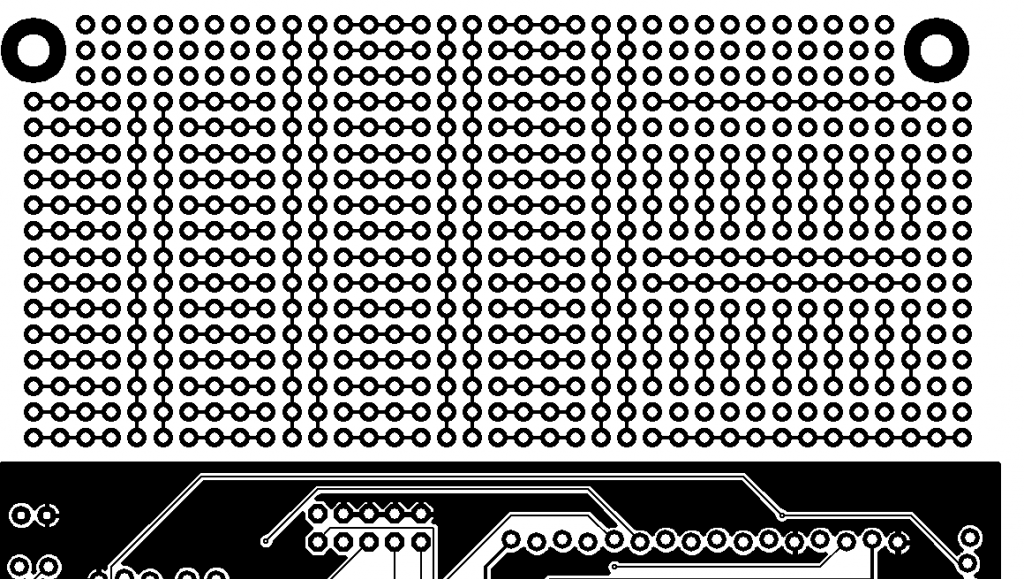
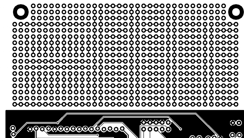
Here it is, This is the view from the top side. All traces are on the bottom of the board, I'm just giving you both views so you can see where components may conflict. My thought initially with the proto area was to have 'breadboard like' sections that IC's could be placed into and the two rails between could be used for power, etc...
Here is the bottom side as you look at it.
Rick |
|
December 28, 2012 by sask55 |
Ralph Because the setup is making use of two independent power supplies and two independent GNDs it is necessary to always clarify from where the voltage is being measured. If things are set up correctly there should never be a voltage measurable across either of the optocouplers . We always need to measure the voltage with respect to the correct GND. There would never likely be any problem connecting the two grounds but it would have no value either. To measure OK1 pin 1 and pin2 or OK 2 pin 4,5 or 6 we need to measure from the micro board GND. There should never be any possibility of a voltage reading from the other pins on these chips to the nerdkit GND. To measure OK2 pin 1 and pin 2 or OK1 pin 4,5 or 6 we need to measure from the USB GND. There should never be any possibility of a voltage reading from the other pins on these chips to the USB GND.. I would be very surprised if the optocoulper has failed or malfunctioned in a way that would allow that to happen since that is the fundamentally the underlying purpose of the optocoupler, ie to keep the two sides electrically isolated even at very high voltages. If any voltage is ever measured across the two sides of either optocoupler it is an indication of a miss connection external to the optocoupler on the setup OK2 is the optocoupker that on the MCU RXD (pin 2) and USB TXD (yellow wire) side of the setup. If there is no voltage on pin1 of OK2, is the hex inverter on working between pins 11 and pins 10 on the 7414 working? Whatever logic state you place on pin 11 pin 10 should be the opposite. There are also four other unused inverters in that chip that could be used if necessary. Basically we are checking both optocouplers and the inverter chip to confirm that the data state is always inverted or flipped from the input side to the output side. In the case of the optocouplers the logic state is inverted as well as the power supply and GND are also changed. 7414 pins13 is an input pin and pin 12 is the corresponding output pin. 7414 pin11 is an input pin and pin 10 is the corresponding output pin. H11L1M pin 1 is the input pin pin 4 is the output pin. You can verify each chip individually if required, ie disconnect any connection from the data pins involved in the test in order to isolate the input and output single to the chip . In that way you can be certain what factors are influencing the input single and the output readings It seams you must still have some missconections that you have not nailed down yet you must be getting close. Darryl |
|
December 28, 2012 by Ralphxyz
|
Thanks Darryl, my head is kinda swimming around. Currently I have a common ground between the USB and the micro should I break it? Thanks Rick for the layout pictures! I didn't realize until I was half way through assembling the circuit that there were traces so I really hacked up the proto area with my Dremel. I am sure I am still missing some traces but now at least I know where they are. Ralph |
|
December 28, 2012 by sask55 |
I would not us a common ground. It should not make any real difference if they share a ground, certainly not under normal circumstances. I setup the insulation circuits with independent grounds because it is just as easy and completely removes any possibility of any stray voltage crossing over from the board to the USB or vice versa. In reality it may be unlikely if even possible to cause any problems on either of nerdkit board or the USB adapter with voltage that may be inadvertently applied to the ground from the other side. However I do have a number of boards set up with 120 Volt AC on part of the board. I will likely be putting together other setups with high voltage with relatively high current capacity in the future. I can be absent minded and distracted at times it is certainly not impossible that I may short out the board and subject the ground to line voltage at some point. I am not certain what the consequences of such a mistake would be for the USB adapter or the computer but with independent grounds I should never have the opportunity to find out. Also independent grounds may be somewhat easier to trouble shoot since it is straight forward to confirm the two sides are not connected. |
|
December 29, 2012 by Ralphxyz
|
I think troubleshooting will be easier with separated grounds so I will separate them or I am thinking about just starting over with a new board luckily I have three of Ricks's original Nerdkit Component boards two of which I have attempted to use so I have one clean one left and now I know how the traces in the proto area run so I will not have to fight with them. Of course I should be building my own PCBs but I just have not gotten to that point yet. Ralph |
|
December 29, 2012 by sask55 |
Ralph I think the major advantage for me in having the USB isolated from the Nerdkit board is when doing any development of a new setup both hardware and software. This is especially the cases on projects where there is high voltage and current within the setup and I am doing USB communications between the PC and micro. I can feel confident that I can leave the USB connected all the time and will not damage the USB or computer no matter what goes wrong on the Miro side of the setup. |
|
December 29, 2012 by Ralphxyz
|
Yeah Darryl, there is a certain reassurance there, protecting the PC from mishaps is important. Now this is strange when I power pin 1 of OK1, 7414 pin 4 stays high, you had said that it should be pulled low. I disconnected R6 the 270 Ω pull-up resistor. With the USB powered OK1 pin 4 is low both when pin 1 is high or low so it appears to be being pulled high all of the time by R6 when it is connected. How is your weather? Ralph |
|
December 29, 2012 by sask55 |
Ralph weather is nice for this time of year -10C daytime high -18 nighttime low very little wind. I assume when you say "Now this is strange when I power pin 1 of OK1, 7414 pin 4 stays high" you meant the pin1 on the 0k1 chip which is not the 7414 chip but one of optocoupler H11L1M chips. If you are certain that you are sending power to that OK1 chip from the USB ie you can measure +5 volts from ok1 pin 5 to pin 6 and you are also certain that you are sending power to the input pin1 on OK1 ie you can measure +5 volts from pin2 to pin 1 on that chip then if the optocoupler is working pin4 on ok1 is low with respect to the USB ground if not the optocoupler does not appear to be working. |
|
December 29, 2012 by sask55 |
I should make a correction to my last post here. The voltage drop measured across the internal LED of the OK1 optocoupler , Pin2 to pin1 will not =5Volts. there will be some voltage drop across the current limiting resistor R2 that is in series with that internal LED. you want to check that there is 5 volts applied across that combination. Darryl |
|
December 29, 2012 by Ralphxyz
|
Damm I was going to setup a new circuit on a breadboard to test, I guess I'll have to setup the circuit to confirm, oh well I have some cold weather coming so I do not have to go outside to play, oh, er I mean work. Ralph |
|
December 30, 2012 by sask55 |
I hope not, but it would be possible to damage (burn out) the internal LED inside the optocoupler chips. If you had ever mistakenly connected pin1 and pin2 of either of the optpcouplers, ok1 OK2, directly across a 5volt source without the current limiting resistor in series with it. the high current flow would likely damage the chip very quickly. If you have a nerd kit type project board or even just a part of a board long enough to place a chip it should take just a few seconds to test each chip. you would nead to power the chip and connect a ground to the correct pins. for the 7414 inverting chip no resistors are required. Just connect a input state of 0 or 5 volts onto a input pin and test the state of the co responding output pin. in the case of the optocoupler chips you will require a current limiting resistor on the input side and a pull up resistor on the output side. this should take a minute or two to carry out. |
|
December 30, 2012 by Ralphxyz
|
I made up a Opto Isolation circuit on a bread board that actually worked the first try :-) so now I have a working circuit to compare with the one we have been discussing. I "think" I must have blown the Opto coupler on the proto board but now I can confirm. Thanks so much for your help and for the circuit, I really like the isolation concept. RE:
That is why I always put the resister on the ground side of the circuit, automatically firs thing whenever I am dealing with LED's or other sensitive components. I have blown LEDs just moving VCC wires around and just touching the LED anode, if I always have the resister on the cathode side I have not blown anything. Ralph |
|
December 30, 2012 by Ralphxyz
|
I replaced the OK1 optocoupler. Luckily I have a nice re-flow station so I was able to remove the chip without much bother. Now pin 4 on OK1 is behaving correctly. Ok1 appears to be behaving correctly. I am testing OK2. You say:
Pin 11 on the 7414 connects to the yellow USB wire. The yellow wire is always high (4.06v) can I/should I connect it to GRN? Won't that make a short on the USB? Ralph |
|
December 30, 2012 by sask55 |
The yellow USB wire is the the TXD from the USB adapter.and that connection to the computor may be pulling it to 4V. if you did connect pin11 on the 7414 pin to the usb GND then yes you would be shorting the adapter TXD to the USB ground. I dont know if that would cause a problem or not in the adapter cable, it is best not to find out. I meant that you should break the connection from the yelow wire to pin 11 and then make a connetion from pin11 to the USB GND. With your settup soldered in place on one of Ricks boards this may not be very easy to do. It would be best to disconect the yellow wire to test the inverter on the 7414 and the OK2.if the setup is not working. so with the yellow wire connected to pin 11 of the 7414 pinn 11 will be high, the inverter in the chip should be making pin 10 low, near 0 volts measured from the USB GND. This woulld mean that pin 1 of OK2 is near 0 volts, from USB ground and therefor pin4 of OK2 should be near 5 Volts with respect to the Nerdkit board ground. with the yellow wire disconected from pin 11 of the 7414 and that pin connected to the USB GND instead. the inverter in the chip should be making pin 10 high, near 5 volts measured from the USB GND. This woulld mean that pin 1 of OK2 is high measured, from USB ground and therefor pin4 of OK2 should be low with respect to the Nerdkit board ground. Darryl |
|
December 31, 2012 by Ralphxyz
|
?? with the 7414 pin 10 high, and the yellow USB wire at GRN, I have 5v. But at pin 1 of OK2 I only have 1.11v is that correct? Seems like 1.11 volts isn't enough to light the internal LED. Ralph |
|
December 31, 2012 by sask55 |
Ralph The low voltage drop of 1.1 volts across the internal LED (Pin1 and pin2) is not indicating a problem. This value is the forward bias voltage of the emitter LED in the chip. most of the voltage drop from 5 volts to GND is occuring through the reistor in series with the chip that is expected. The H11L1VM-ND optocouplers I am using are Schmitt trigger output type, basically the output will be in one of two states, nothing in between. According to the data sheet as little as 1 mA of input current (Pins 1 and 2) should result in the output pin(4) being pull low. The important thing to check is, if that 5 volt output from pin 10 on the inverter result in the change in the output from pin 4 of the optocoupler. Check that when the voltage of 1.1 volts (to USB GND) is measurable on pin1 the voltage on pin 4 drops to near zero with respect to the Nerdkit ground. |
|
January 01, 2013 by Ralphxyz
|
Hoo Weeee!! Well apparently replacing the optocoupler fixed the problem. I had also replaced the mcu power switch but it was not making contact (I'll speak to Rick about that) so that was messing up with my testing. Thanks so much Darryl for sticking with me, I apologize that this has taken so long to sort out, I am afraid I am getting kinda slow, But it WORKS!! Ralph |
|
January 01, 2013 by sask55 |
You're welcome Good to hear it is now working. Darryl |
Please log in to post a reply.
|
Did you know that you can control 120 LEDs with just 17 microcontroller pins? Learn more...
|


Copyright © 2013 by NerdKits, L.L.C.