Digital Calipers DRO (Digital Read Out)

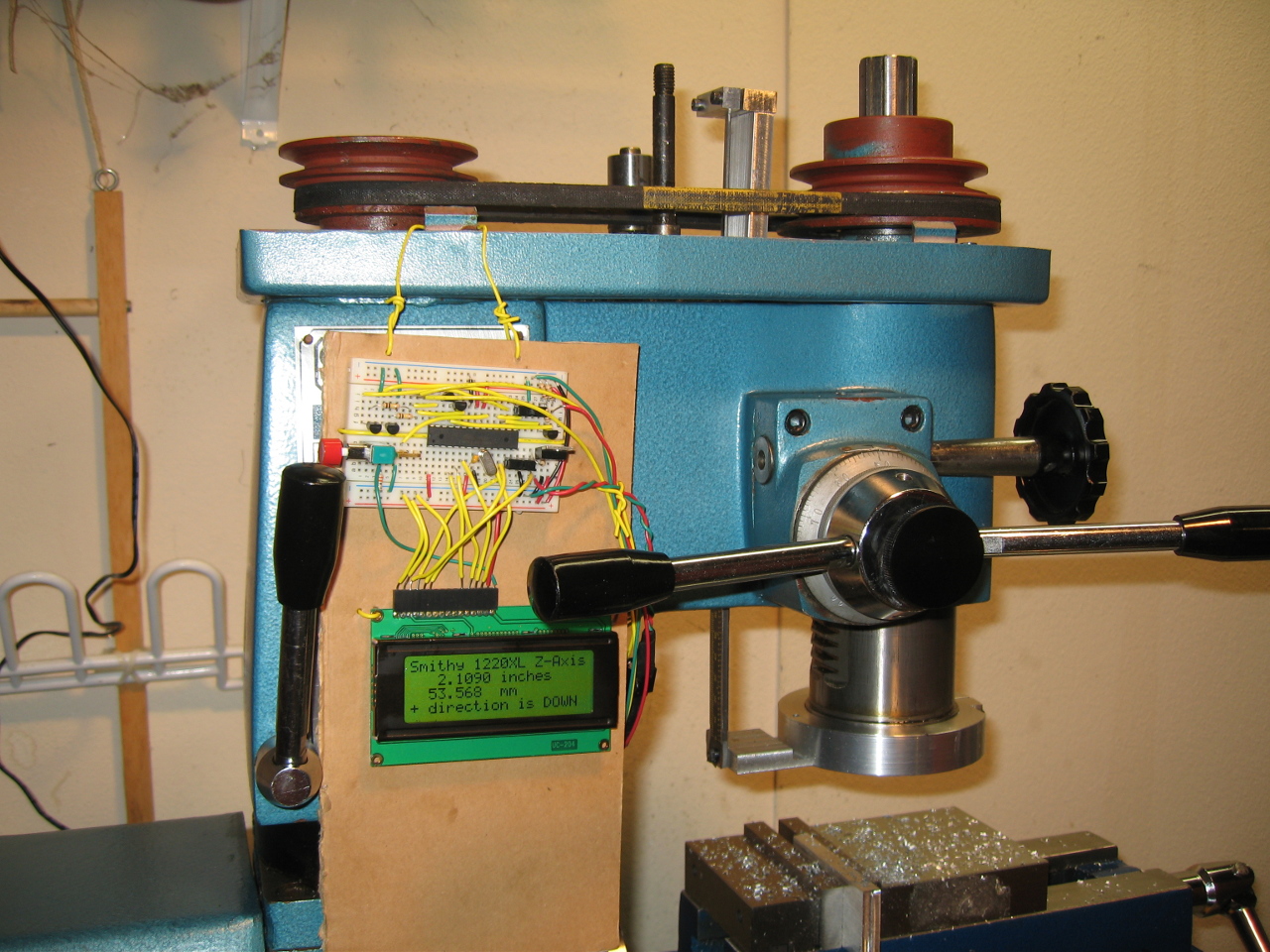
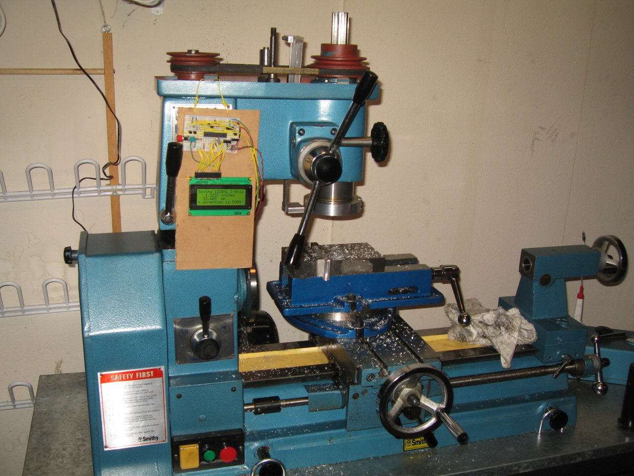
We recently got a Smithy 1220XL lathe / mill combo machine, but we quickly found that the 0.042" resolution ticks on the milling head's Z-axis were a big limitation. In this video tutorial, we show how we used a USB NerdKit plus a digital caliper to create a simple digital read out, or DRO, for this machine's Z-axis. The video above talks about how we built it, including the mechanical implementation, the code, as well as some electronics concepts such as how to interface buttons and switches to a microcontroller. Read on for more details!
Click any photo to enlarge:
Quick links:
Mechanical Design
In order to measure the vertical movement of the quill, we have to hold the caliper parallel to the quill and couple their movement rigidly, while trying to avoid the potential for misalignment and binding. Using the lathe and mill, we manufactured six aluminum pieces that together hold the calipers to the quill and millhead casting.
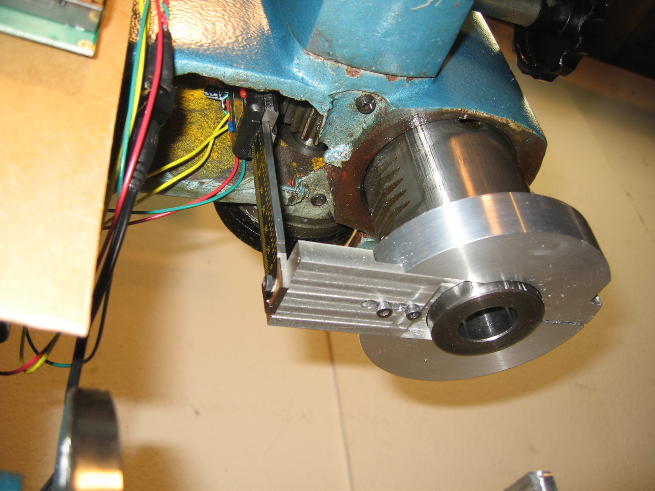
On the bottom side, we started with a 4" diameter x 3/4" thick round of 6061 aluminum, and turned it into a clamping quill collar. The outer diameter and thickness are essentially arbitrary. There are two bored inner diameters. The innermost bore diameter is a clearance bore for the rotating spindle. It must stay clear of the rotating spindle, but stay close in order to prevent metal chips from being kicked up into the tapered roller bearing that sits between the quill and spindle, just above the collar. The second and larger bore diameter which is a press-fit for the quill's 2.908" outer diameter, at a depth of about 0.350". We then made a radial slot through the piece using a reciprocating saw, and tapped two #6-32 holes tangentially through the slot. This lets us gently tap the collar into place with a rubber mallet, and then tighten the screws to securely clamp the collar in place. (We were inspired by Ned Seith's quill collar design for his Smithy Granite 1324, but his design may offer a bit more rigidity.)
Next, we started with 1.5"x3/8" aluminum 6061 bar stock, and machined an arm that comes out radially from the collar. In order to ensure that only a minimal amount of material protrudes below the spindle (to avoid hitting a workpiece, particularly when using smaller end mills in a collet), we used only 0.150" thickness for the part that interfaces with the collar, and machined a 0.150" deep channel in the collar to match. Only the screwheads protrude below the surface. A slot was cut into the arm and allows for about 1/4" of radial adjustment. There is a radial tapped #6-32 hole, which is where the end of the caliper beam connects.
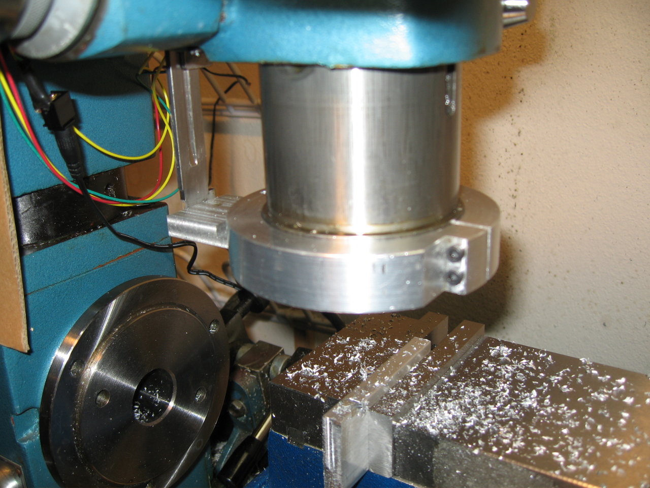
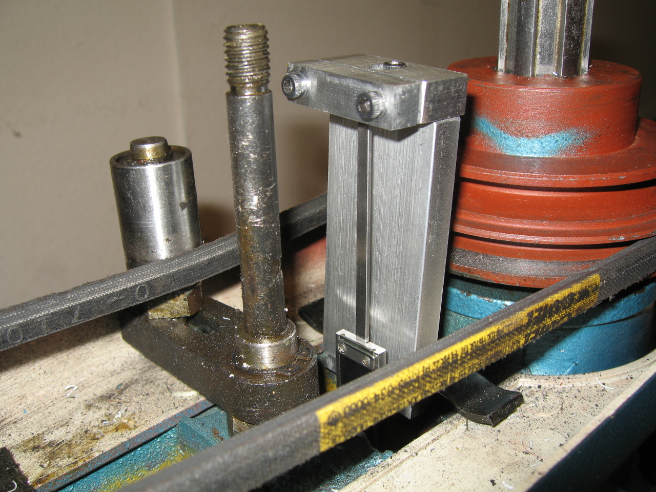
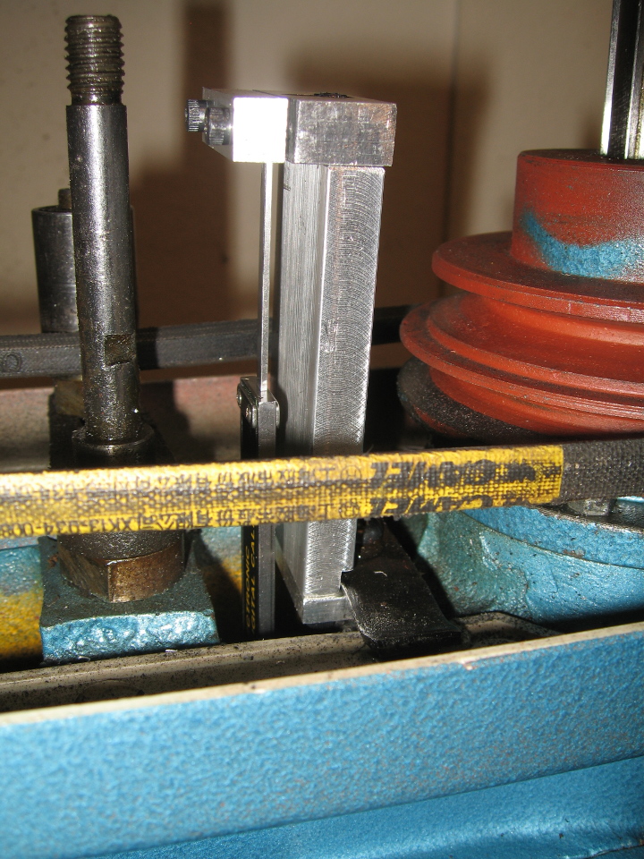
On the top side, we started with 1.5"x3/8" aluminum 6061 bar stock and machined a bracket and clamp in four parts, screwed together with #6-32 hardware. The bottom-most piece lies horizontally in a space that was previously unused, and uses a screw and clamp originally designed to hold the plastic milling head cover in place (see the 4th photo). A 3.050" long vertical bar lets raises the system high enough to allow full travel of the calipers, while just clearing the top piece of the plastic cover. Finally, a clamp is formed in two pieces, letting us secure the end of the caliper rod.
There are several points at which the various angles and distances can be adjusted, which allows us to make sure that the caliper beam is not stressed and will not bind before we tighten everything. However, there are two drawbacks that we recognize to this approach: one is that there is the possibility for a form of "cosine error" -- the caliper axis may not be truly parallel to the quill axis. Another is that we are clamping on a fairly small cross-section piece at the top, instead of on the reading head directly, so there is the possibility for deflection (buckling) along the length of the calipers. However, for a mill Z-axis, this is mitigated by the fact that essentially all operations occur as the quill is lowered, leaving the smaller beam in tension, where this deflection is limited to linear elastic stretching, without buckling (which can happen only in compression).
All in all, the mechanical implementation seems to work well, with no noticable added drag on the quill, and no noticeable backlash. While building everything, there were several occasions when which we wished we had the finshed DRO to help us in our work!
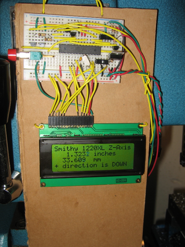
Buttons, Switches, and Pull-up Resistors
In this project, we are using one pushbutton and one switch to act as elements of the DRO "user interface". The pushbutton, when pressed, resets the counted distance to zero, which is a useful operation to zero off a surface during an alignment and machining operation. The switch toggles which direction is considered positive relative to the origin. (For this Z-axis application, the switch is not particularly necessary because all of the cutting on a milling machine goes "down". However, when we later consider X and Y-axes, switching the direction might be more useful. For the lathe mode of operation, switching between radius and diameter readout will also be very useful.)
So how do you connect a switch or button to a microcontroller?
A microcontroller's input pin reads a voltage, and decides to treat it as a digital 1 or 0. If you look at the ATmega168 datasheet, under Electrical Characteristics on page 304 you'll find definitions for VIL (Input Low Voltage) and VIH (Input High Voltage). When powering the chip from 5 volts, those limits are VIL = 1.5 volts and VIH = 3.0 volts. This means that any voltage at an input pin of 1.5 volts or less is guaranteed to be considered a logical "0", and any voltage greater than 3.0 volts is guaranteed to be considered a logical "1". (The range between these two voltages is intentionally left undefined in order to allow for some manufacturing tolerance and variation over other factors like operating temperature, or even hysteresis, in order to allow the manufacturer to make chips less expensive! The microcontroller will read the voltage as either as a 0 or 1 -- but the chip makes no guarantee as to which one.)
First, let's take a quick look at buttons and switches:
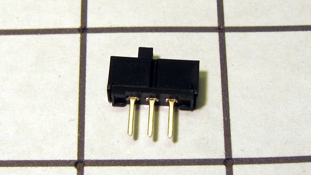
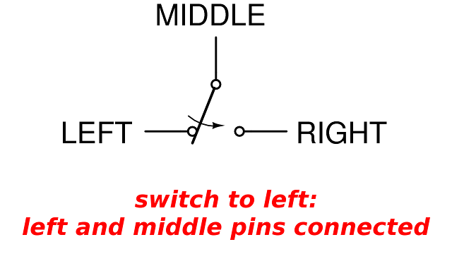
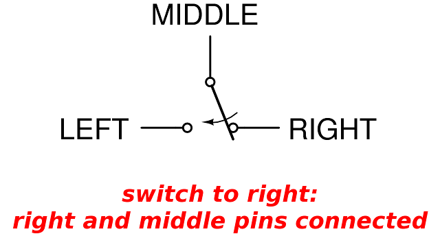
This is an SPDT switch, where SPDT stands for "Single Pole, Double Throw". This means that the mechanical action of the switch moves 1 terminal between 2 possibilities. One terminal (here, the center one) is a common terminal, and when the switch is moved left or right, that common terminal is connected to the corresponding side terminal.
(Other common switch types you may encounter are: an SPST switch ("Single Pole, Single Throw"), in which there is one connection point which is either connected to a second point, or not connected to anything at all. This would look like our SPDT switch above with either the left or right terminal removed. Another common type is a DPDT switch ("Double Pole, Double Throw"), which is like two SPDT switches which are mechanically linked together. This can be useful when there are two indepedent signals that should be switched at the same time -- for example, a stereo audio signal carried over separate left and right channels might be switched between two different sources using a DPDT switch.)
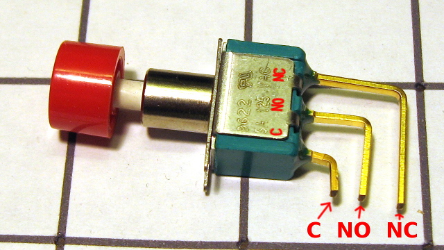
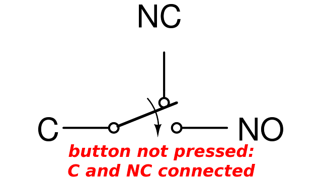
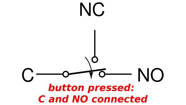
Here is a momentary pushbutton, where a spring is used to keep the plunger in one position when no force is being applied. This one is similar to an SPDT switch in that it has three terminals, but because the pushbutton has a spring and a "default" or "normal" state, these three terminals also carry special names and labels: NO for "Normally Open", NC for "Normally Closed", and C for "Common". The C terminal is like our middle terminal of the SPDT switch above. When the button is not being pressed, C and NC are connected (and NO is disconnected). When the button is pressed, C and NO are connected (and NC is disconnected).
Another useful datapoint is that the resistance of a typical mechanical switch, when closed, is generally much less than 1 ohm. (Membrane switches, like those found in keypads, may be significantly higher.) If this switch resistance is much smaller than the other resistances in your circuit, it can often be ignored, but if it's comparable to the resistance of whatever is being switched, then you must consider heating and voltage drop inside the switch itself.
Now that we've discussed how the microcontroller's input pin recognizes voltages as digital 1s and 0s, and how switches and buttons work, it's finally time to put the two concepts together and use switches as inputs to the microcontroller.
One option for connecting a switch to a microcontroller is to force a microcontroller pin's voltage directly to 0 or to +5V via the switch or button. For the pushbutton above, this would mean connecting the C terminal to the microcontroller pin, and connecting the NO to GND and the NC pin to +5V (or vice versa). For the switch, this would mean connecting the center terminal to the microcontroller, and the left and right pins to GND and +5V. This would work -- at every instant, the microcontroller pin is connected to one or the other (except for the brief transitions as the switch moves between its mechanical stops).
However, there's another way that's very commonly seen for connecting buttons and switches to microcontroller circuits. By using a "pull-up resistor" connected between the microcontroller pin and the high voltage supply, we can omit the switch connection to +5V. Now, when the switch is open (not connected), the resistor keeps the microcontroller input pin voltage high for a logical "1". When the switch is closed (connected), the switch resistance and the pull-up resistance form a voltage divider, but the switch resistance is so small in comparison that the microcontroller input pin's voltage is practically zero, allowing it to be read as a logical "0".
The primary advantage to connecting a switch or button with the pull-up resistor technique is that the switch/button is not required to be "double throw" -- it can simply be a make/brake SPST switch. This gives you a wider selection of possible switches and buttons. This also means that there are fewer wires in the circuit. Finally, the pull-up resistor itself doesn't need to be added as an external component. Each microcontroller pin has a built-in pull-up resistor that can be enabled by one line of code. According to the Electrical Characteristics in the ATmega168 datasheets, RPU is between 20 to 50 kiloOhms -- a perfectly good range for use with buttons or switches of sub-1 ohm resistance. When the switch is open, no power is consumed, and when the switch is closed, at most (5 volts)/(20K ohms)=250μA of current flows through the switch.
So after the discussion of buttons, switches, and pull-up resistors, the final implementation is actually quite simple: we connect one terminal of the switch or button to ground, and the other to the microcontroller's input pin! Then, we activate the internal pull-up resistor for that pin, and we're then able to read the state of the switch as a digital 1 or 0.
(There can be further implementation details, like "debouncing" a switch, but we'll save that for a future tutorial, because it isn't relevant to this application.)
Digital Calipers Communication Protocol
We started with an inexpensive 6" long digital caliper, similar to this one from Amazon.com. (We bought ours on eBay many years ago, so we can't guarantee that this one is 100% identical, but it looks very similar.)
These calipers output a synchronous (clocked) digital signal. The caliper periodically outputs a group of 48 bits, with a bit period of about 12μs. The first 24 bits are a signed integer representation of distance, with 20480 bits per inch. The relative timings are important because, although it is a synchronous protocol and each data bit is aligned with a clock edge, the relative times between clock edges (idle times) indicate when a new group of data starts. In particular, we wait for at least ~50μs of quiet in order to indicate that a new set of data is about to begin.
The specific details of handling the electronic interface to the scale is described below. A great reference for the protocol is available from Shumatech, which was very helpful during our development work.
Two's Complement Notation
In the code, we have the read_bits() function which reads every bit one by one and stores it into a 32-bit signed integer. When dealing with negative numbers in binary, particularly because we are building a signed integer bit by bit, we have to understand how the computer represents negative numbers in binary.
Humans represent negative numbers in decimal notation by putting a "-" sign in front of the digit. So if I had the number 42, I would represent the negative number as -42. When a number is represented in binary we do not have the luxury of just adding a negative sign, so we have to represent negative numbers using only the 1s and 0s we already have. Computers generally represent negative numbers using a system known as two's complement notation. Technically, the two's complement representation of a number is found by subtracting the number from two raised to the number of bits wide your data type is. So to find the two's complement of 4 as an 8-bit number, I would subtract 2^8 - 4 in binary, which would be 0b100000000 - 0b00000100, which would result in 0b11111100.
This system might seem needlessly convoluted, but it actually makes a lot of sense since it makes negative numbers behave naturally with all the arithmetic operations we would do with unsigned numbers. Two's complement numbers work perfectly if you just think of them as counting backwards. Say you start with 0b00000010 (2 in decimal) and start counting backwards, 0b00000001 (1 in decimal), then 0b0000000 (0 in decimal), so if I want to keep counting down I just overflow in the negative direction and get 0b11111111 (-1 in decimal) and so on.
This system might be confusing at first, but it allows the processor to handle negative numbers in the exact same way it handles positive numbers. This means it can add positive four and negative four and get 0 like you would expect (try it on paper). The same hold true for multiplication, subtraction, and the rest of the arithmetic operations. This concept is explained quite well in several different ways on the two's complement Wikipedia page
With two's complement notation however, you do have to be careful about sign extending numbers correctly when moving from one size integer to another. When dealing with positive numbers you generally don't have to worry about it because it just adds 0s in front of the number. For example if you had a 4 bit integer 0b0010 (2 in decimal), and you turned that into an 8 bit integer you get 0b00000010 (also 2 in decimal). However with negative numbers if you have a 4 bit 0b1110 (-2 in decimal) and make that into an 8bit integer you need to pad the extra spaces with 1s so that 0b1111110 (also -2 in decimal). This is what is happening in the read bits_function() at the end when we take a look at the most significant bit, and decide whether to pad the remainder of the number with 1s. The digital calipers are already giving us a two's complement number, but it is only 24 bits. Since we want to extend that number into a 32bit signed integer, we need to sign extended it based on the most significant bit.
Power Supply Circuit
In order to power the calipers themselves from the same wall transformer supply we'll be using for the microcontroller and LCD, we have to produce a roughly 1.5 volt output to replace the calipers' small button cell battery. Quick measurement with digital multimeters revealed that the calipers only consumed 10-20 μA.
The simplest approach to transforming one known voltage to another lower voltage is with a two-resistor voltage divider: two resistors in series between the voltage source and ground. In the image below, considering the input to be VIN and only considering resistors R1 and R2, the voltage at the midpoint is VOUT=VIN*R2/(R1+R2). However, that assumes that no current is actually drawn from that terminal -- clearly false since the calipers must draw some current to be useful! As more current is drawn from that middle terminal, the voltage decreases.
This gives us a chance to briefly talk about the concept of Thevenin equivalent circuits. The basic idea is that we can look at a circuit that's made up out of voltage sources and resistors, and consider any two terminals. We can then reduce it to simply one voltage source plus one resistor -- the Thevenin equivalent values -- and when only measuring from those two terminals, the original circuit and its Thevenin equivalent will be indistinguishable from outside. This means that if you put a voltmeter across the two terminals, you'll get the same measurement, and as you draw current, they'll still stay in sync.
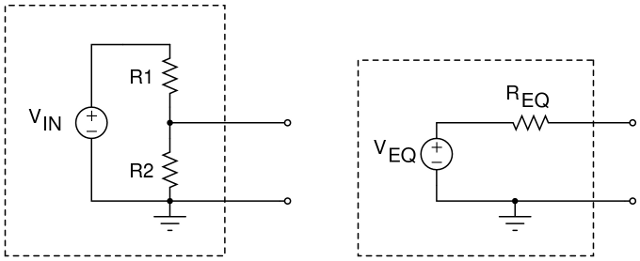
In the schematic above, we can choose VEQ=VIN*R2/(R1+R2) and also REQ=(R1*R2)/(R1+R2), and this will make these circuits behave identically. The concept of Thevenin equivalent circuits is powerful, because it lets us take one linear circuit and replace it with a simpler one, which makes it easier to construct an I-versus-V curve (like we discuss in The NerdKits Guide) or make other decisions about a circuit.
If we want to take our 5V source and use it to create a 1.5V source to act as a power supply for the calipers, we want to pick R1 and R2 (and specifically the ratio of R1 to R2) so that the first equation is satisfied and VEQ=1.5V. But a battery has a voltage that is fairly constant over a wide range of currents -- certainly beyond the 10-20 μA that the calipers draw. In order to be sure that the voltage supplied stays "close enough" to 1.5V, we have to keep REQ small, so that the voltage drop I*REQ stays small. We can certainly do that by making R1 and R2 arbitrarily small, and in theory, this will work to produce a satisfactorily "stiff" voltage supply.
However, by making R1 and R2 smaller resistances, the amount of current consumed goes up, even if no current is actually consumed by the calipers. This current is essentially wasted in just holding the circuit at its desired operating point -- and good engineers should attempt to minimize it if possible. This current is sometimes called "quiescent current".
Don't let the Thevenin equivalent circuit drawing above convince you that there is zero current consumed when the circuit is unloaded! The Thevenin equivalent can be helpful when we're considering what a circuit looks like from "outside the box" -- but "inside the box", R1 and R2 are still there forming a current path, and consuming current of VIN/(R1+R2) even when no current is heading to the external terminals. Our battery or power supply still has to provide this current, so making R1 and R2 arbitrarily small is a bad idea.
Instead of relying only on resistors, we can add one transistor, and ultimately we can get the benefits of low effective output resistance but still have low quiescent current!
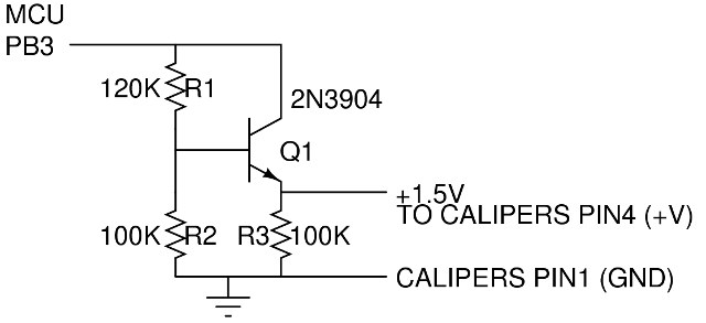
In the schematic above, we're using R1 and R2 as a voltage divider, but instead of being biased toward our desired 1.5V, we're aiming for about 2.1 to 2.2V, and the simple reason is that it's 0.6 to 0.7 volts above the desired 1.5V target. The 0.6 to 0.7 volts are just a very typical base-emitter forward voltage to a silicon NPN transistor, and its consistency is one of the benefits that makes designing with BJTs easy! But basically, over a wide range of operating currents, an NPN transistor's emitter terminal will stay at about 0.6 to 0.7 volts lower than its base terminal.
Next, since we knew that we were aiming for an operating current of about 10-20 μA, that meant that Q1 required a base current of perhaps 100 nA (the collector current divided by the current gain of the transistor -- perhaps 100). Now, the I*REQ voltage drop to worry about was reduced by a factor of the transistor's current gain! This may be a challenge to understand if you're new to looking at transistor circuits, but the big idea is that the effective output resistance has been basically reduced by a factor of 100 with essentially no extra power consumption! This works because extra current drawn from the emitter (to the calipers) requires only maybe 1/100th of that current to be drawn from R1 and R2. (This is a bit of a simplification, but it's quite good in this case.) Finally, R3 was added as a safety mechanism to assure that some current would be flowing to prevent the output voltage from getting too high on startup.
We also found that it important to add a bypass capacitor at the calipers. Without the battery, the sensitive analog electronics in the caliper head performed poorly and the output was very jumpy. We soldered a single 10μF electrolytic capacitor right at the caliper terminals to alleviate noise issues.
For another project where we dive further into the details and math of using an NPN BJT transistor, see our Piezoelectric Sound Meter tutorial.
Digital Level Shifter Circuit
As discussed earlier in the Buttons and Switches section, the microcontroller recognizes voltages lower than 1.5V as "0", and higher than 3.0V as "1". However, the digital calipers are outputting a digital signal that was only 1.5V for "1"! The signal is too small to interface directly to the microcontroller. We had to build a very simple level-shifting circuit to amplify the difference between the 0 and 1.5V levels up to being big enough for the 5V logic levels of the microcontroller:
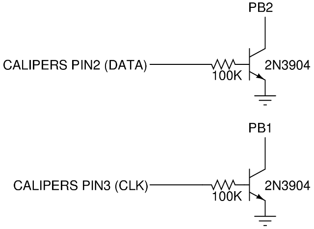
We simply used one NPN transistor and one resistor, plus the pull-up resistor integrated into the microcontroller's input pin. The pull-up resistor keeps the microcontroller pin voltage high when the caliper signal is low. When the caliper signal goes to +1.5V, the transistor is able to turn on, and with the base-emitter voltage of 0.6 to 0.7V, there's about 8 μA flowing into the base of the transistor. Because of the transistor's current gain, there's easily 100 times as much current flowing into the collector, which means 800 μA. This, combined with the 20 kiloOhm minimum pull-up resistance, means a 16 volt drop -- which is impossible when the pull-up resistor's other end is only connected to +5V via the microcontroller. This means that the transistor is actually in saturation, and the current gain is lower than the factor of 100 mentioned above, but that the transistor is firmly pulling the microcontroller pin voltage down toward about 0.2 volts.
There are certainly more complicated ways to go about level shifting, but this is a straightforward way that works for these relatively slow forms of digital logic. (For higher speeds of digital logic, we have to consider various capacitances in this circuit, and may have to tune the design somewhat to switch between states fast enough!)
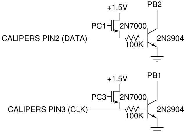
Hi-Speed Readout Mode Circuit
Per the advice on the Shumatech site linked to earlier, we discovered that it's possible to put the calipers into a special high-speed mode, where it provides output about 40 times per second instead of the default ~3 times per second. To allow our microcontroller code to automatically switch into that mode when powered on, we added two 2N7000 MOSFETs between the 1.5V power supply and the clock and data lines.
See the source code for details about how we toggle these lines upon startup.
Source Code
You can download the source code here.
More Videos and Projects!
Take a look at more videos and microcontroller projects!
Comments
|
Did you know that the microcontroller's crystal oscillator can be used to keep accurate time? Learn more...
|


Copyright © 2013 by NerdKits, L.L.C.