NEW: Learning electronics? Ask your questions on the new Electronics Questions & Answers site hosted by CircuitLab.
Project Help and Ideas » Pocket LED Array
|
May 19, 2010 by Phrank916 |
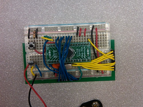
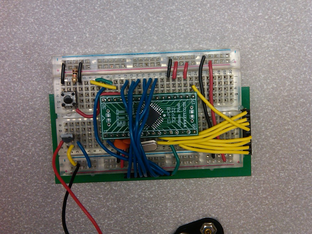
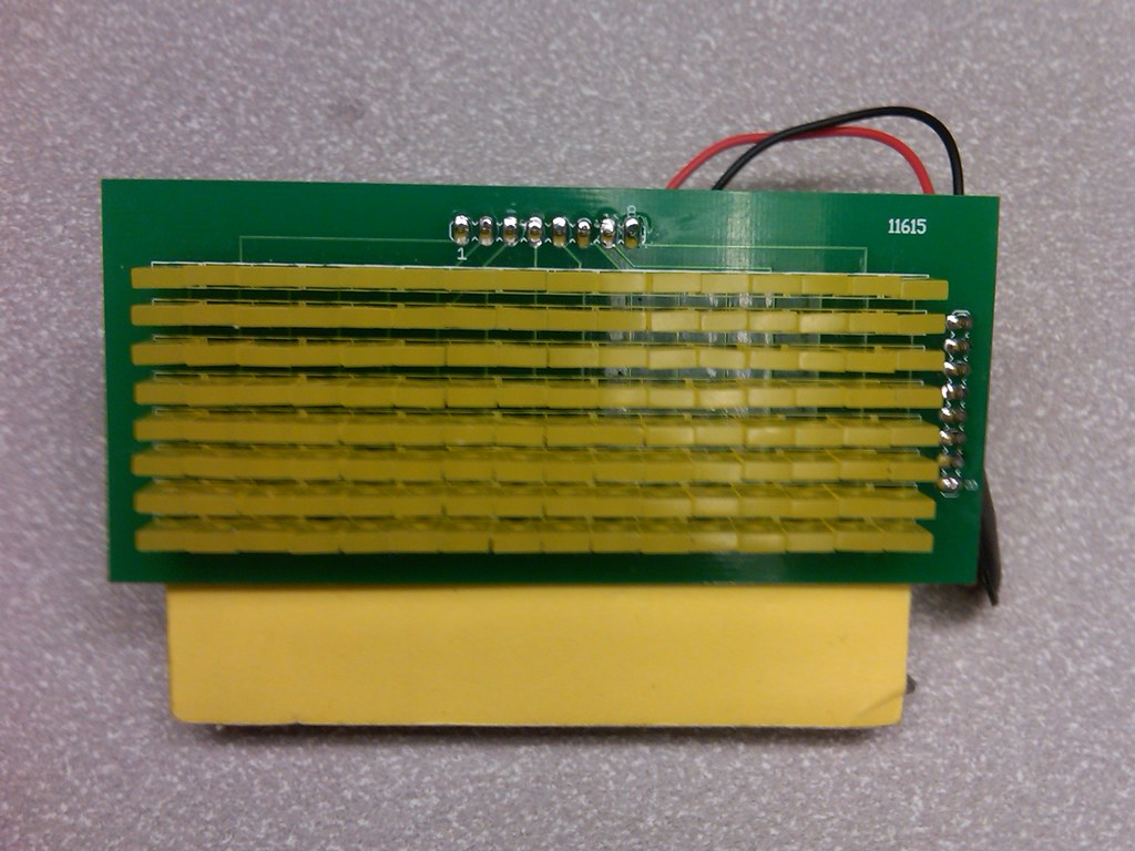
Hey Nerdkits friends! I haven't been posting much in the forums lately, life and all that, but I still have been plugging away at various projects when I have an hour or two. I recently made some more modifications to my 16x8 LED array PCB. I finally got ahold of a couple TQFP 328p MCUs and mounted one to the little breakout board you can see in the middle of the breadboard in the first photo. I tried to reduce the circuit size and the 16 array wires as much as possible. The plan next is to lay the circuit out in Eagle and use all SMD parts so I can make a really low profile board that attaches to the back of the array with headers. Once that is done I want to also add a mini-USB port so it can be powered off USB or battery and put it in a project case so it can be my portable "desktop" array and sit next to my computer spitting out RSS feeds or whatever. Should be fun if I can find the time and resources. Ted |
|---|---|
|
May 19, 2010 by mcai8sh4 
|
That looks sweet - really nice work! It'd be nice to see a little vid of this bad boy in action if possible. I would like to make a similar thing, (ie small led array) that can be embedded in a particular item of clothing for comedy reasons. |
|
May 19, 2010 by Phrank916 |
Steve- Thanks! The youtube vids off the original thread are the same exact array, just in the earlier stages of the circuit with the spaghetti wiring, etc. Check it out: YouTube link #1 Lately I've been putting it on the back of my daughter's bike trailer when we go riding at night with a message that reads "SLOW DOWN!! BABY ON BOARD!!!", heheh. I'll get a video of that later tonight if we go out riding. Ted |
|
May 27, 2010 by Phrank916 |
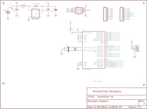
So, I'm trying to design a controller board for this array. I have been playing with Eagle and have come up with a schematic for this. I was wondering if anyone could give me any tips on this circuit. I know I have the USB connector hooked up wrong, I haven't researched that enough. I'd also like to add the PL-2303 chip if possible on the board so it can be directly plugged into any computer with just a mini-usb cable, as long as the Prolific driver is installed of course. The power supply incorporates a DC step up (NCP1400) so I can use a single AA battery to power it if I want to, but I think it will be mostly powered off the USB. Anyway here's the schematic: Ted |
|
May 27, 2010 by Phrank916 |
Also, just remembered that I didn't notate the value on some of the components. e.g. -the crystal I want to use is this one, which has a load capcitance of 12pf. I found a formula for figuring the value of the two decoupling capacitors but I'm not sure if it's right: Cᴸ is the load capacitance value and Cˢ is supposed to represent the "stray" capacitance in the circuit. I have no idea how to find this out but on the site where I found this formula it was stated that stray capacitance is usally 2-5pf. So, if I plug in 12pf for the load capacitance and add the stray capacitance of 3pf I get a suggested value for the decoupling caps of 18pf. So, would the standard 22pf caps be OK for this application? Ted |
Please log in to post a reply.
|
Did you know that microcontrollers have two different kinds of memory, program space (flash) and SRAM? Learn more...
|


Copyright © 2013 by NerdKits, L.L.C.

