NEW: Learning electronics? Ask your questions on the new Electronics Questions & Answers site hosted by CircuitLab.
Project Help and Ideas » PCB for LED array
|
February 24, 2010 by Phrank916 |
I got a whole bunch of 2mm x 5mm rectangular LEDs when I got those grab-bags of LEDs off eBay about a month ago. So, I decided I wanted to put them to use and play around with Eagle at the same time. So I've created a 2-sided PCB to create a small, almost handheld array with the LEDs basically all butted up against each other, no spacing. I've also decided to make it an 8X16 array with 128 LEDs. Check out my design, I thought it came out pretty good! The dimensions are 3.7" x 1.7"
I actually went ahead and submitted an order to BatchPCB for two copies of the design, which I should receive in about 3-4 weeks. I'll let you all know how it turns out! Ted |
|---|---|
|
February 26, 2010 by Rick_S 
|
How did the BatchPCB process go? I've thought of trying to put something together to order from them but wasn't sure my Eagle skills were up to par to have files they could use. Did the default settings in eagle do it for you or did you have to get a custom design rule file? Do you have a special project in mind for your new boards? Also, on another note, did you get the LTK tip yet?? How do you like it? Rick |
|
February 26, 2010 by Phrank916 |
Rick - I haven't got the boards back yet so I don't know the final outcome, I guess it can take up to 4 weeks. The process wasn't too hard, I found all the info on the SparkFun tutorials, which are now hidden for some reason, maybe outdated? This was about my third attempt at trying to create something within Eagle. I have been working on another small board for a TQFP ATmega32, but that's gonna take some time and more practice, so I thought I'd try and create something simple and I needed an excuse to use up some of these rectangular 2x5mm LEDs that I am up to my ears in. So yeah, I just followed the tutorials which you can now find by going to the embedded electronics ones, then click the little "breadcrumb" link at the top and that takes you back to the tutorial index where there will now be about 5 more that weren't there before. One cool thing I did, because I didn't have the SparkFun library on the computer I was using, was I created my own part from the standard library of footprints. That wasn't to hard, once you get an idea of how the parts are created, I made my own library and dragged a footprint from another library, then I had to grab the LED schematic symbol from the symbol library and then put them together and make the connections and voila, a new part. The not-so-fun part of this was lining up 128 LED symbols on a schematic, then doing it all over again on the board, making sure the A/K orientation was correct for each one. I hadn't planned on sending this out to BatchPCB, I was actually considering trying to teach myself the toner-transfer method and make my own double sided PCB. The problem with that is you can get pads on both sides, but they aren't plated-through, so I would've had to solder one leg of each LED from the top and one from the bottom, or let lots of solder wick through from the bottom to the top while soldering..and that doesn't sound fun either.. After checking the prices at the BatchPCB website and realizing it wasn't too awfully expensive, I honestly think it was just an impulse buy! I really want to see what they can do with my amatuer design! I don't plan on making anything in particular, I guess I'm just challenging myself to create a different aspect-ratio array. This one will be 8X16, and I've already created an 8x5 pixel font, and the code shouldn't be too hard to modify, since it's already setup with COLS and ROWS as variables, etc. If you do ever try and send something in to BatchPCB, definitely use the SparkFun CAM file because it seems to create the exact files you need for submission. The tutorials explain all that too. I am for sure planning to design and make some more PCBs in the future, it combines a lot of my loves: design, electronics, and meticulous perfectionism, ROFL, all into one! I am still very much interested in making my own at home using the toner-transfer or UV methods, one-sided at least! To answer your final question about the LTK tip, no I haven't bought that one yet. I still plan to. I'm using the one that's a 1.6mm wedge. it's between the LTK and the LTB. It's a little too wide for some things, but I have smaller ones too if needed. Well, I've rambled on enough. I'll post my new 8 pixel font a little later if you're interested. It includes lower-case letters! I'm still working on transferring it from graph paper to the font.h file though, so it might be a bit. Cheers! Ted |
|
February 26, 2010 by Rick_S
|
For single sided boards, you should go for it. I've made several. I use hydrogen peroxide and muratic acid for the etchant. It works great. Made one today as a matter of fact. I built one of THESE. Instead of sending the caps-lock, I sent the backspace. I figure this will drive my co-worker nuts. My real job is a CNC-Machine programmer. I use a program called MasterCAM to generate code that metal cutting mills and lathes use to make parts. My co-worker always has an internet browser open and we are always typing instructions for the machinists and operators for running the programs. I plan "attack" on April 1st. It's going to be hard to keep a straight face when his browser goes back on it's own or he's typing away and a character he just type disappears! I've thought of trying batchpcb, I just wasn't sure if I'd know how to generate all the files they need and how to check them to make sure they are right. You've given me some courage though. Maybe I'll give it a shot. Rick |
|
February 26, 2010 by mcai8sh4 
|
Sorry to jump in (I don't want to hijack this thread, but...) Rick, can you make a similar "caps-lock-thingumy" using an ATMega168? -Steve |
|
February 26, 2010 by Rick_S
|
I'm sure it could be done. However, I didn't make the initial program. All I did was modify the keystroke it was sending. I know the base USB code is used in the USBASP programmer and those run on mega8's and mega48's. Someone posted a comment on that page (near the bottom) saying they used an ATmega128. The code for the tiny45 uses the internal oscillator and adjusts it's own speed to synchronize with the usb clock. So it's code definately will not work without serious modification. Whether or not the 14.7456 crystal would work I'm not sure. I know people have used 16 and most commonly 12. Rick |
|
February 26, 2010 by mcai8sh4
|
Thanks for the info - gives me something to think about. </hijack> -Steve |
|
February 27, 2010 by Phrank916 |
Rick- You should somehow get video of your co-worker's reaction, I'm sure it will be priceless! I guess I'm gonna have to try my hand at making one of those and get my feet wet in home PCB etching. It looks like it's a lot of fun to get the finished product. Oh and on the Eagle files, that tutorial tells you exactly which ones they are gonna need, and they give a link to "Viewplot" which displays the Gerber and drill files like they are gonna be seen by the Chinese manufacturer. You should go for it, I've read on the forums where people keep ending up with double or triple their order because if a single board on your panel needs to be re-run, they re-run the whole panel of course and you reap the benefits of the extras. Kinda cool. Steve- QUIT HIJACKING THREADS! Just kidding, it's all good. No worries man. |
|
February 28, 2010 by pbfy0 |
I'm pretty sure 14.7456 mhz will not work because it doesn't divide nicely into 1.5 or 12 (speed of USB 1.1) |
|
March 15, 2010 by Phrank916 |
Just got an email saying my PCB has shipped. I should receive it in a couple days. I'll post pics when it arrives. |
|
March 16, 2010 by Phrank916 |
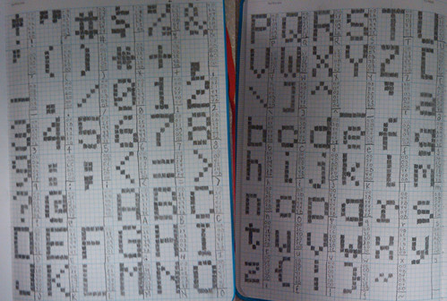
I've finished the new 5X8 font and got it all converted to hex. Here's a pic of my layout on graph paper.
And here is a link to my new font.c file. Let me know if anyone ends up using it, I'll be curious to know how it works out. Ted |
|
March 16, 2010 by bretm 
|
That's cool. It will probably come in handy. I noticed that the "t" came out like instead of what you show in the picture. 0x3E needed instead of 0x3D? |
|
March 16, 2010 by Phrank916 |
Good catch! You are absolutely right, that should be 0x3E. I did it all by hand and in my head, even the coding into hex, so I knew there would be some errors. I figured I'd see them later when I started trying to utilize the font. I'll update the file in a bit and re-upload it. |
|
March 16, 2010 by Rick_S
|
Wow, I bet it took a lot of time coloring in all those squares on the graph paper. You have more patience than I!! I can't wait to see your final project. I bet it'll be great! |
|
March 19, 2010 by Phrank916 |
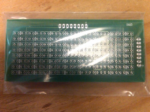
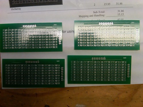
PCBs ARRIVED!
As I mentioned earlier in this thread, I've read about a lot of customers receiving double their order becasue if one single board on a huge panel gets messed up they have to re-run the whole panel, so I wondered if I'd get that lucky... YEP!
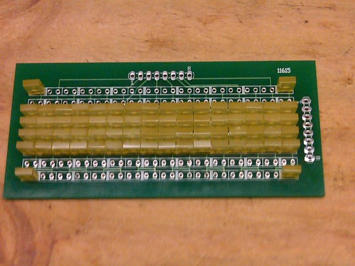
I started soldering LEDs last night beginning with the four corner ones and after 2 hours of soldering I am half done. 68 LEDs and 136 solder points so far, 60 LEDS and 120 points left!
I should finish the soldering tonight but I still have some coding work ahead of me. More to come! Ted |
|
March 19, 2010 by mcai8sh4
|
Ted, they look cool!!! You could make a light up belt buckle, or ANYTHING.... Don't forget to post your final result :) Nice one mate. -Steve |
|
March 19, 2010 by Rick_S
|
Eagerly awaiting the end result!! Boards look good and didn't take too long. |
|
March 19, 2010 by Solorbob |
It looks like a fun project. I can't wait to see how this turns out. |
|
March 21, 2010 by Phrank916 |
Well folks, here it is: The Mini-Array!! I was extrememly surprised at how easy the code was to modify once I got into it. It was really just adding a few FOR/ELSE loops to turn on the right row drivers since the pins had to be re-arranged a bit. I also added Rick's primary function of right to left scrolling, just had to change a few 23s to 15s and that function worked perfectly. I did come to realize that I had a really messed up font file. It has been renamed to font.h and I was missing closing semi-colons all the way down, LOL. I will post the final build of this modification tomorrow after I clean it up a bit along with the corrected font.h file. This was a really fun build, the soldering was excellent practice for me and making the new font was especially cool to actually see it scrolling across in lights! I have 3 of the PCBs left, not sure what I'll do with them yet, but if anyone is interested in this build, I can make the PCB public in the "marketplace" on BatchPCB and you can order a copy of it straight from them. Or bribe me for one of the extras, hehe! Ted |
|
March 22, 2010 by Rick_S
|
Ted, That looks great!!! Fantastic job. You should give yourself a pat on the back for a job well done. Did it end up using the same amount of pins on the micro-controller as the original?? Rick |
|
March 22, 2010 by Phrank916 |
Thanks, Rick. I actually used one less pin on the MCU from the original 5X24 array. In hindsight I wish I would have just used the same amount, then I could've added two more columns making it an 8x18 array. Removing the UART feed would also free up two more pins and allow you to make it an 8X22 display, but that would be more for turning it into something like a static-message, wearable sign like a namebadge or a belt buckle as Steve mentioned! :) I'm now dreaming up a design for a small single sided board that I can make at home and add to the back of the array. I want to power the array with USB power and control it with a TQFP MCU and a few SMD parts to make it as compact as possible and turn it into a cool little desktop toy with a micro USB port on the side, etc. I think I would also like to find a good source for the brightest 2mmx5mm LEDs out there. The yellow ones I used are a bit dim for a brightly lit room or outdoor viewing. Here is my final code with the corrected font.h file and the makefile included. Ted |
|
March 23, 2010 by Phrank916 |
Here's one more video clip of the array in a darkened room, running a full character test pattern. Ted |
Please log in to post a reply.
|
Did you know that you can use a transistor to interface between different voltage levels of digital logic? Learn more...
|


Copyright © 2013 by NerdKits, L.L.C.