NEW: Learning electronics? Ask your questions on the new Electronics Questions & Answers site hosted by CircuitLab.
Project Help and Ideas » pwm fan control
|
April 26, 2010 by justinvice |
i am using an atmeag168 microcontroller and would like to see an example of a pwm fan control....i can handle the programming, but i am not clear of how to setup my breadboard for testing. the servo controller is good stuff, but i could not get a good look at how to configure the breadboard. |
|---|---|
|
April 27, 2010 by hevans (NerdKits Staff) 
|
Hi justinvice, Take a look at our motors and microcontrollers tutorial It has more information about the electrical side of driving motors (most fans are just DC motors). Hope that helps. Humberto |
|
April 27, 2010 by justinvice |
i have seen that tutorial and (as i mentioned in my original post) the servo project. however, i still am not quite clear on how to configure my bread board |
|
April 28, 2010 by hevans (NerdKits Staff)
|
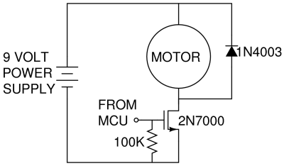
Hi justinvice, I apologize, when you said the servo project I assumed you meant the servo squirter project, it goes over the basic concepts behind using PWM to control servo motors. Our motors and microcontrollers tutorial does not use or cover any servo motors, just DC motors. Since you are trying to drive a fan (most likely a DC motor) you were in the right place looking at the motors tutorial, although I also recommend taking a look at the servo squirter tutorial, as it has a much deeper discussion of PWM. There are thousands of ways a breadboard can be wired up to still achieve same circuit, so instead of explaining a breadboard layout, you will get much more out of it if you can turn an electrical schematic into a breadboard layout of your own. The schematic to pay attention to is this one
The motor is connected with one teminal at the positive rail, and the other terminal connected to the drain of a 2n7000 mosfet. The source of the mosfet is connected to GND. The gate of the mosfet is connected to the pin on the MCU that is outputing the PWM (this is set by the code). This circuit will allow current to flow through the motor when the MCU is holding the pin high, and current will not flow when the pin is low, effectively giving you the ability to turn the motor on and off with your mcu. There is a diode connected across the leads of the motor, as well as a resistor from the gate of the mosfet to GND. The reason for these is explained in the tutorial. Let us know if some part of this doesn't make sense, or if something I said was unclear. I will try to do a better job at explaining it. Humberto |
|
November 20, 2010 by tkopriva 
|
I was reviewing the motor controls project and noticed two things: there is a resistor Connecting the RESET pin (pin 1) to the +5V rail (versus a wire like in the starter guide), and there is what seems to be a capacitor near the bottom left of the breadboard. Both these components weren't noted in the explanation. Can you expand on what they are used for? Thanks Tom |
|
November 20, 2010 by tkopriva
|
I guess the more specific question is I wired up the push button portion of the project with success, to power a DC fan, and would like to know if missing one of those two components is a dangerous thing. See below for my circuitry (my power source is 4 AA batteries). If anyone has any pointers I would really appreciate it! Thanks Tom
|
|
November 21, 2010 by Rick_S 
|
Not dagerous at all. The resistor on the reset pin is not an uncommon practice especially if you want to add a reset button to the micro. This allows you to connect (even though they don't have one in the tutorial) a momentary (normally open) switch from pin 1 to ground, with a pullup resistor from pin 1 to VCC. That way when the reset button is pressed, pin 1 is pulled to ground resetting the chip and the power rail, because of the resistor, is not direct shorted. The capacitor you see is by the regulator. If you notice, they are using a wall wart power supply in place of the battey. A non regulated wall wart dc supply often provides "noisy" power. The capacitor will help filter some of that noise out and fill the voids if there are minor drop outs that can be created in the AC to DC rectification process. With battery power there is no real need for this capacitor as the power is clean. Keep in mind though, powering a motor will drain your battery very quickly. If you look down at the bottom of this thread, you'll see a basic setup for the reset button I've used many times. It saves having to disconnect and re-connect the battery to re-program. Rick |
|
November 22, 2010 by tkopriva
|
Thanks Rick! As you eluded to the fan did drain the motor quickly I will need to go to a wall AC to DC converter, especially since I taking temperature readings that start to fall off as the power goes away. I have a wall AC to DC converter handy that is output rated at 12 VDC and 300 mA. Can you expand on how I would use a capacitor to filter the noise and fill the power voids (where it goes in the circuit and what size to use)? Tom |
|
November 22, 2010 by Rick_S
|
An electrolytic 10 to 100uf cap would be fine rated for 16V or more. Simply connect it near the regulator on the input side across the input +V and Ground. Remember that electrolytic caps are polarized so make sure the side marked as negative goes to ground. Rick |
|
November 22, 2010 by tkopriva
|
Great, thanks for the help! Tom |
|
December 04, 2010 by tkopriva
|
I attempted to integrate the LCD to get some real time feedback--like in the Motors and Microcontrollers 101 demo. However, when I use a wall power supply the first and third row illuminate without characters. The starter guide implies that this means, "First and third row of LCD turns on, but no characters are displayed. Diagnosis: This means the LCD is getting power, but not getting any data it recognizes." However, I can use a 9 volt battery and all is well...So I assume I need to modify the 1k resistor for the now 12V power supply. Any tips on how to fix this issue? Thanks Tom |
|
December 05, 2010 by hevans (NerdKits Staff)
|
Hi tkopriva, It is possible you are not hooking up your power supply correctly and that is causing a problem that is causing your chip not to run. The resistor should no need to be modified because it is placed between the 5V of the voltage regulator and the LCD. The 7805 will regulate the 9V of the battery and the 12V of the regulator to the same 5V. If you can post some pictures of your setup we might be able to help you debug the issue. Humberto |
|
December 06, 2010 by tkopriva
|
Hi Humberto, no problem, as is shown I am connecting power to input and ground to the common ground rail for both the battery and the 12 Volt power supply. For the battery the LCD works, for the power supply it does not....
Thanks Tom |
|
December 07, 2010 by hevans (NerdKits Staff)
|
Hi tkopriva, I don't immediately see anything wrong. I am a little concerned about your power connections on the right side of the breadboard. Are those extra wires going to the temperature sensor? I also can't see the contrast resistor so that might be in the wrong place. Do you have a multimeter around. Have you tried checking the voltage your AC adapter is putting out? What voltage do you get across the power rails when you are running the kit of the AC adapter? Humberto |
Please log in to post a reply.
|
Did you know that you can connect digital calipers to a microcontroller? Learn more...
|


Copyright © 2013 by NerdKits, L.L.C.