NEW: Learning electronics? Ask your questions on the new Electronics Questions & Answers site hosted by CircuitLab.
Customer Testimonials » Thought for additional component to NerdKit
|
November 22, 2009 by Rick_S 
|
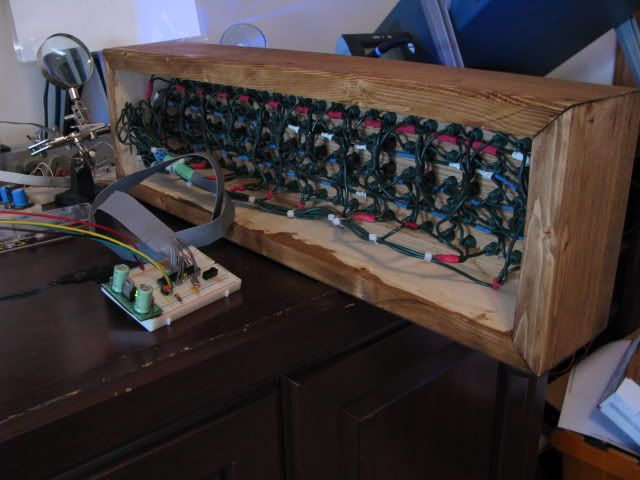
Have you guys tossed around the idea of adding a N/O tactile switch and 10K resistor to the kit for a reset circuit. You have the reset tied high. By adding the resistor and switch, you can program the chip without having to disconnect power. Just slide the program switch over, press the reset and it's now ready to load. This little addition came in very handy when I was testing my code for my marquee. You can see the reset button and resistor in this photo.
Just thought this may be an inexpensive but valuable addition to future kits. Rick |
|---|---|
|
November 23, 2009 by tech20 |
yes, that would be pretty useful on the nerdkit, but on the subject of additional components, wouldn't a few chips from the 7400 series and a LM358 be useful, just in themselves, those chips would be great, in use with the nerdkit, a few chips (even one) of each main logic type(and, or, nand, nor, xor) would be worthwhile, especially on the way to explaining on how logic works out. |
|
November 24, 2009 by Rick_S
|
While I agree that some additional I.C.s may be nice for some. They may not be applicable for many. There are several people who don't care to dabble in the world of analog signals and would have no use in an LM358 op amp. Basic AND, OR, NAND, NOR, and XOR logic can all be performed in the micro-controller program. While the use of these externals can come in handy at times, they would also require much more breadboard space as well as a higher current draw on the standard 9v battery. That was one of the reasons that I only suggested a simple reset button. This is a component that everyone with a Nerdkit could use right out of the box. It requires no learning curve. It's simple and straightforward. It requires virtually no additional breadboard space. It vastly simplifies programming. I agree the components you suggested would make a great addition. I think however, that maybe adding them to the store as an accessory pack would be a better option. That way those who are interested in expanding could make the purchase and those who have no need of them wouldn't have to pay extra for parts that will sit in a drawer. JM2C :D Rick |
|
November 24, 2009 by tech20 |
Oh yes, a additional pack would be better, and possibly a larger breadboard for sale with it. The switch is probably the best addition though, if it was the only one. A additional kit though, for those who want to learn more about the logic, or just use for other projects would be good to. |
|
November 24, 2009 by mcai8sh4 
|
I'll throw my thoughts in... I think an additional pack, containing useful/fun/informative items would be a nice addition to the store, then people who want to take it further can, plus since the parts are coming from Nerdkits (so everyone gets the same part), it will be easier for other members of the forums to help people like me (...what do I do with this?...) However it would also then lead to our fine hosts, Mike and Humberto, addressing these parts in some new tutorials. Anyway, the main reason I wanted to post to this thread... Rick_S : I really must congratulate you on your LED display - fantastic. Could you please explain the switch system to me a little more? I think I get the idea, but not 100%. Close-up pic may help with the wiring, but the general 'why' it works has me puzzled. Thanks -Steve |
|
November 24, 2009 by Rick_S
|
Pin one is the reset line of the micro-controller. With the default wiring of the kit, a wire is placed from the +5v bus to pin on thus pulling it high at all times. If that wire is replaced with a 10K resistor and a N/O (Normally Open) momentary (only contacts when pressed) switch is placed between pin one and ground then any time you press the switch, the CPU will reset. Thus to program the controller all you have to do is flip the program switch to program mode and press and release the reset button. This eliminates the need to disconnect and re-connect the power to program. The little red pushbutton switch you see in the photo above actually came off an old cable box control panel. These are all over the place in old electronics and can normally be easily removed and re-purposed. I'll see if I can get a pic up after I get home from work. (on lunch now :) ) |
|
November 24, 2009 by mcai8sh4
|
Rick : Thanks for the info - I get it now (almost)... why the 10K resistor? There's no need for the photo now, I appreciate your time and can picture the setup without you having to go to the trouble. Thanks again, nice idea that! |
|
November 24, 2009 by Rick_S
|
The 10k resistor is the pullup. Without that, when you pressed the button, you would short your 5v directly to ground. The pullup resistor reduces the current flow through the switch when pressed. |
|
November 24, 2009 by Farmerjoecoledge 
|
Okay, what position is the switch in? I mean the one that comes with. For programing normally, up to program, down to run. I appreciate this idea, so all you do is keep the switch up, leave it powered and just press the reset. No, you would flip the switch up and then hit reset, and then down again to run? Sorry for being so trivial, but i'm programmer less so can't test it. For anyone who doesn't quite understand pullup resistor, they "call" it a pullup not because of what it looks like, but because of where the 10k "regular" resistor is "placed" in the circuit.In this case it's before the switch, hence pull-up. |
|
November 25, 2009 by Rick_S
|
The program switch would stay in it's run position until you were ready to program. At which point, you would slide the program switch into the program position and press reset. This would re-boot the micro-controller in programming mode. Once programming is finished, you would slide the program switch back to the run position, again press the reset button and then the chip would re-boot in run mode. The reset eliminates having to power down/up to re-boot the chip. |
|
January 12, 2010 by Phrank916 |
I simply used the extra switch the kit came with to give my breadboard an on/off switch. I do like the idea of using the M/O switch though on the reset pin. My setup just has the positive lead of my old re-purposed LG phone charger going into one side of the switch then a wire from the middle post to the +5 rail. The other side of the switch is connected to nothing of course. I placed an order with Sparkfun yesterday and ordered 6 of their little M/O switches which fit breadboards perfectly. I'm gonna set one up as a reset when they arrive for sure. It's really only a smidgen easier than sliding my on/off switch, but I think it might be a better option and possibly a little easier on the MCU. You can sorta see my on/off switch in the top right of my breadboard in this pic. Ted |
|
January 12, 2010 by Rick_S
|
Switches like the ones you are getting are just what I was speaking of in my initial posting. That combined with a 10K pullup resistor on the reset line makes re-programming of the Micro-Controller much simpler. At least is is for me... :D I'm sure you'll find them useful as well. I snagged a half dozen or so of those off an old cable box control panel. I love harvesting parts off old electronics... it's amazing what you can find sometimes. Rick |
|
January 12, 2010 by BobaMosfet 
|
If there was one component that should be added, I think that would be of the most benefit to noobs and experts alike, it would have to be a diode. Yes, a humble diode to put between the power-supply and the regulator input pin (PIN 1). I'm thinking something along the line of a 1N5818. The point being to prevent someone's circuit getting torched if they get polarity backwards on the power-supply-- something all to easy to do, for someone who doesn't know anything about power, and just as easy to do by those of us who are confident in our abilities as well. I know it's saved me TWICE. I keep telling myself I know what I'm doing.... :D |
|
January 13, 2010 by Rick_S
|
Excellent point. The humble diode can be a life (or chip) saver! |
|
January 13, 2010 by Phrank916 |
I did that very thing the other day. Reversed the polarity of my power source when I was trying to move my little two position on/off switch to the other side of the breadboard. Luckily I caught myself before plugging in the wall wart! Rick, I had a question of clarification with the reset switch setup. So, if I understand correctly you replaced the wire from the +5 rail to PIN 1 with a 10k resitor. But then the button is connected one side to the ground rail and the other side ALSO to PIN 1? So when the momentary on switch is pressed the ground rail is connected too?! I guess I'm not understanding why you'd connect both rails to PIN 1. I know the 10k resistor is somehow preventing a short across that PIN but is enough current getting through the resistor when the switch is open to keep that pin high? Or am I totally confused and over thinking this? Ted |
|
January 13, 2010 by Phrank916 |
Oh, and I am with you on the part salvaging! I've totally been looking at old pieces of electronics and boards from old computers differently now. I'm now looking at them trying to see if there's anything interesting that I can put to good use. I can't wait to get a decent soldering iron and get to work with that and my solder wick pulling things apart. Sounds like good fun! Maybe someday I'll be able to afford a hot-air rework station :) Ted |
|
January 13, 2010 by Phrank916 |
P.S. - I'm so jealous of your "very recent model" digital Weller I can see in the background of the photo above! |
|
January 13, 2010 by Rick_S
|
You are correct that the 10K resistor replaces the jumper wire to the 5V rail. The N/O Momentary switch then goes from pin 1 to ground. This way when the button is not pressed, pin1 is pulled high with the resistor, when the button is pressed, pin one is pulled low through the switch. The purpose for the resistor is so that when you press the button, you don't create a direct short between the 5V and ground rails. The resistor restricts the amount of current flow. Pin 1 is a hardware reset line for the micro-controller. This line will reset the chip when pulled low. The reason for keeping it pulled high whether through a straight jumper or a resistor is to prevent it from floating. Which in theory could cause random re-boots of the chip.
As for the soldering station, it was a very generous gift from my boss at work for doing some side electronic work for him. I never would have purchased a station like that myself but WOW... is it nice. Heats up in seconds, holds it's heat well, couldn't ask for more. :D Rick |
|
January 21, 2010 by Phrank916 |
Thanks Rick, I got the switches the other day that I had ordered and set it up just like your picture. Works great! |
|
June 22, 2011 by Ralphxyz 
|
Hey Rick I have been meaning to ask you if it is just me. Well, you said at the beginning [quote] "By adding the resistor and switch, you can program the chip without having to disconnect power. Just slide the program switch over, press the reset and it's now ready to load." [/quote] Using my Mac mini I cannot not reset to programming mode. If I am in programing mode I can switch to "RUN" mode and hit the reset and run the program. But if I am in "RUN" mode nothing happens when I hit reset until I power off. From your description it seems as if I should be able to go back and forth without powering on/off. Ralph |
|
June 22, 2011 by Rick_S
|
If it's wired correctly and the reset button is still enabled, directly connecting it to ground will reset the micro-controller - regardless of programming environment. When the micro get's reset, the bootloader should take over as long as the switch is in the correct spot. You didn't by any chance put the resistor on the wrong side of the switch did you??? Rick |
|
June 22, 2011 by Ralphxyz
|
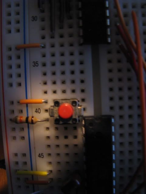
Well it works normally with pin1 pulled high as the Nerdkit User Guide illustrates. Here is a picture of the setup do you see any thing wrong?
How would one put the resister on the wrong side of the switch? I have the 10k resister between pin1 and Vcc (+). With a Normally open switch between pin1 and ground. On both my Mac mini and my Windows 7 x64 Ultimate I get the same results, I can not switch to programming mode and reset unless I power off. The reset switch does absolutely nothing in RUN mode, it doesn't even make the LCD flicker! It does exactly as you describe if I power off, switch to programming mode, power on in programming mode, switch to RUN mode and hit RESET it switches to RUN mode without having to power off. Ralph |
|
June 22, 2011 by Noter 
|
Maybe you are confused by what is shown on the display? When you switch to programming mode followed by a reset, the display remains unchanged but you can download because in fact the bootloader is running. Compared to when you power off and then switch to programming mode, the display has not been initalized and therefore shows the black bars. Either way, the bootloader is running and you can download. |
|
June 23, 2011 by Rick_S
|
I agree with Noter, wired the way you describe, the mcu has to reset. As soon as the reset pin is pulled low by pressing the switch, the mcu will reboot. However as Noter also stated, your display won't change because it's internal memory still contains valid data and has power. Did you try to upload a program and it fail? Remember, a 2 black line display does NOT mean you are in program mode, it just means the display hasn't been initialized. (Which happens to be the state it's in while running the bootloader after a power cycle) Rick P.S. Yeah, After reading that, I did just rephrase pretty much everything Noter Said |
|
June 23, 2011 by Ralphxyz
|
Well in theory I agree with Noter also. That is the way it is supposed to work. Actually I switched to a different breadboard and it does work as you both have described!!! TaDah!! I had had problems with the breadboard that was not reseting so had set it aside. Yesterday I thought I'd try it again and it was working fine using power on/off as the reset. Then I added the reset button and it didn't work on reset except when in programming mode. Now that breadboard is once again not working at all so I think I will just strip it and start anew. Its a large breadboard (3900 contact points) so there are a lot of jumpers. Thanks again for the help. It's interesting as I usually have to switch the yellow usb wire off after programing in order to run a program as has been discussed often here in the forum. So far I have not had to do that with the breadboard that is working with the reset. I have another large breadboard (one I made up) that I will also have to test with the reset button. I have had problems with using the large breadboards (multiple boards) they seem to work for a while and then start acting goofy. I do not have as much problems with the single board breadboards such as the one that is working with the reset button. Thanks again, Ralph |
|
June 23, 2011 by Noter
|
You can use 2N7000 mosfet transistors for Q1 and Q2 to eliminate that yellow wire problem.
|
|
June 24, 2011 by Ralphxyz
|
Thanks Paul, I have moved my questions to a new thread in Electronics as I do not want to hijack this important thread. It appears using the Reset button alleviates the problem I have had with the yellow wire keeping the mcu energized but I'd sure like to talk about your circuit. Ralph |
Please log in to post a reply.
|
Did you know that two resistors can be used to make a voltage divider? Learn more...
|


Copyright © 2013 by NerdKits, L.L.C.

 That's just because I think he's totally hit the mark on this.