LCD Backlight - Electroluminescent Inverter

There are two major types of backlights for LCDs: LEDs, which stands for light emitting diode, or EL, which stands for electroluminescent. EL backlights tend to be more efficient and have more uniform lighting than LED ones, but they require some tricky circuitry to drive. If you've heard of Organic LED displays, or OLEDs, that's basically an array of electroluminescent strips shunk down to the size of individual pixels.
Every kit shipped before 4/07/2009 has an LCD which actually includes an electroluminescent backlight. Kits shipped on 4/07/2009 or newer have an LED-based backlight, so this video does not apply.
Electroluminescent backlights are hard to drive because they actually require about 100 volts AC at around 150 Hz, and we're just running our logic off 5 volts DC. But we can use an inductor to generate these high voltages.
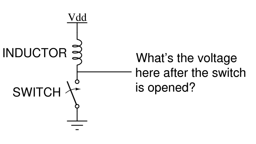
After a current is allowed to build up in the inductor, the switch is opened. The fundamental device law of any inductor is V=L*dI/dt, where dI/dt is the change in current per time. So if the current is asked to change from something to zero basically instantly, a huge voltage will be present. (For our actual circuit, we measured a 300V peak and roughly 100mA of peak inductor current, which means dI/dt=3,000,000 Amps/second, or switching off in about 33ns! This matches well to the 22ns rise time listed on the IRF730A datasheet.)
Schematic
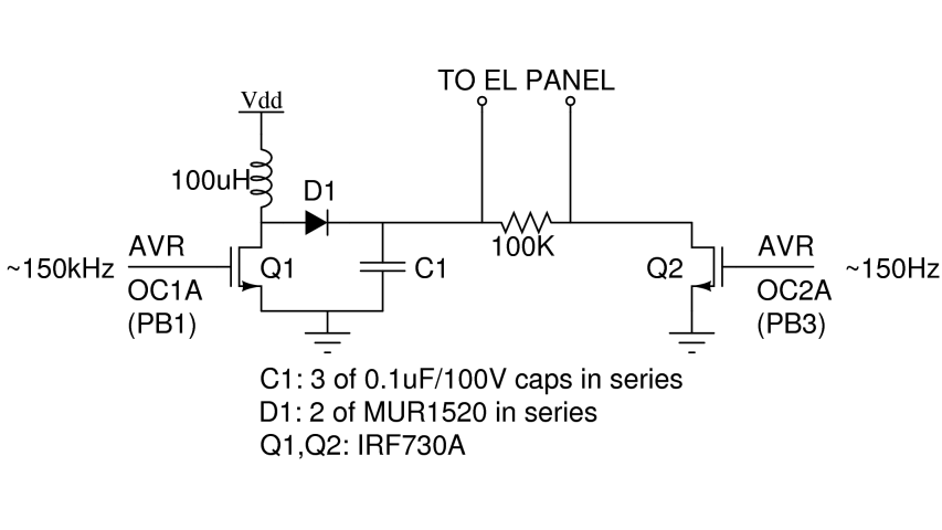
Q1 and the 100uH inductor are just the switch and inductor described above.
Whenever the voltage on the unconstrained end of the inductor is greater than the voltage across C1, diode D1 lets charge flow and further charge C1. This is basically a peak detector, finding the maximum to make a smooth DC signal.
The 100K resistor guarantees that if Q2 is open, the electroluminescent panel will have zero voltage across it, because the 100K resistor will discharge the very small capacitance (not shown) in the electroluminescent panel itself. The electroluminescent panel sees the high voltage across it only when Q2 is pulling the right EL wire down to ground.
The AVR microcontroller generates two square waves from its Timer 1 and Timer 2 units. The brightness can be varied most directly by adjusting the frequency driving Q1. A faster frequency means there is less time for current to build up in the inductor before it switches off, leading to a smaller dI/dt and therefore a smaller voltage spike.
Parts List
| Photo | Part | Quantity | Description |
|---|---|---|---|
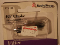 |
100uH Inductor, Radio Shack 273-102 | 1 | This was the only inductor for sale at our local Radio Shack... so that was an early design constraint! :-) |
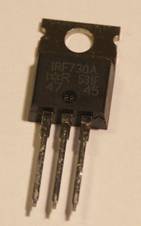 |
High-voltage n-channel MOSFET, IRF730A | 2 | We need two switches, Q1 and Q2, for our circuit. These MOSFETs in particular can withstand 400V before undergoing drain-source breakdown. This breakdown voltage is important, because it means that at a particular voltage (when the MOSFET is OFF), the drain-source will begin to conduct even though the gate is being held low. Since this is something we clearly want to avoid (as it'd discharge our capacitor at the wrong time), we need to find special MOSFETs like these with particularly high breakdown voltages. |
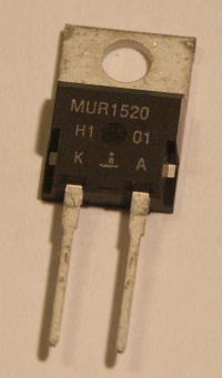 |
Fast switching diode, MUR1520 | 2 | These can withstand 200V of repetitive reverse voltage before breakdown, so we decided to use 2 of them in series to provide a total of 400V of reverse breakdown protection. (We originally used a 1N914 but destroyed it due to the high voltages imposed as we were testing the limits of our circuit.) |
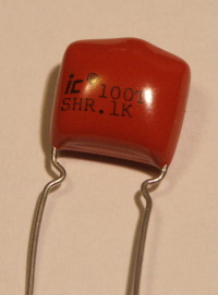 |
High voltage capacitor, 0.1uF @ 100V | 3 | We didn't have any high voltage capacitors on hand, so we used three equal capacitors in series to get a voltage rating of 300V -- the lowest in our system. You may know that capacitors in series produce a smaller overall capacitance, but that's OK here, because we really just need the higher voltage limit. So overall, we'll have 33.3nF of capacitance with a 300V limit. |
Step 1: Solder to the electroluminescent backlight
There are two terminals on the right side of the NerdKits LCD panel. Solder wires on to get access to them.
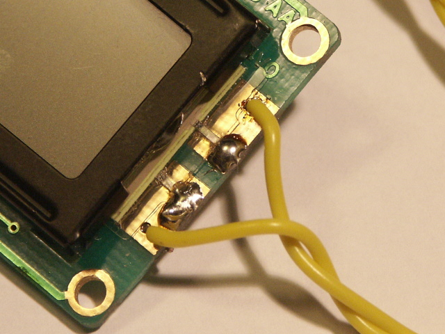
(click photo to enlarge)
Step 2: Use a DC Power Adapter
This circuit draws too much current to run off the 9V battery for very long. We used a 12V DC wall transformer, cutting off the connector. Measure the voltage at the end, especially to get +/- correct. Then, just plug it into the NerdKit where you currently have the 9V battery clip. Anything roughly in the 7V to 20V range will work.
We also added one 4.7uF and one 0.1uF capacitor across the power rails to help reject voltage ripple from the transformer.
Step 3: Build the circuit
Following the schematic above, build the circuit. Here's what our's looked like:
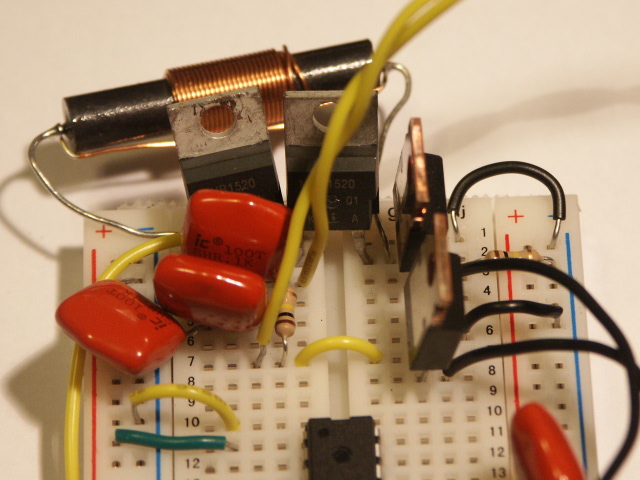
(click photo to enlarge)
Note: One end of the inductor is connected to "Vdd" and not +5V. In this case, connect it directly to the input of the 7805 voltage regulator -- which comes directly from the wall transformer. This helps make for a bigger output voltage, and also helps by significantly reducing the power that needs to be dissipated by the 7805.
Step 4: Upload the software
Download the source code, and then make a new NerdKits project just like you would any other -- starting from a template project included with the kit and modifying the Makefile.
More Videos and Projects!
Take a look at more videos and microcontroller projects!
Comments
|
Did you know that a NerdKit can be used to build an iPhone-controlled R/C car? Learn more...
|


Copyright © 2013 by NerdKits, L.L.C.