NEW: Learning electronics? Ask your questions on the new Electronics Questions & Answers site hosted by CircuitLab.
Basic Electronics » Need help with electronics using a op-amp
|
August 12, 2010 by Ralphxyz 
|
This is in conjunction with my thread about tying a strain gage to the MCU:. I have tested a strain gage (transducer) and find that I am getting a tenth of a milivolt variable signal. For 20# .5mv 30# .6mv 40# .7mv and for 70# I got .8 mv. Now I want/need to tie the output to the Nerdkit MCU ADC. I am not a electronics engineer, I am not even a electronics hobbyist. I am just a curious unemployed guy (not strange, just curious about all this wonderful technology surrounding us) who needs some understanding about a op-amp. Actually I do not even know if a op-amp is the best way to go. Any way I need to amplify my tenths of a millivolt signal up to a millivolt or even 100 millivolt signal to read in/on the MCU. I have a LM324N Quad OP-Amp I got at Radio Shack but that seems to want Vcc between 15 - 32 volt. This doesn't seem to fit my design criteria which of course I haven't the slightest idea what I am doing but it just seems like a lot to ask to just multiply a millivolt by a 100. I also have some 741 op-amps and I'll gladly order some thing else from Mouser or other suppliers if needed. So what might be a op-amp that i could use the same power supply as the Nerdkit? I have a great supply of wall warts with multiple outputs so I am flexible in power supplies output. I use a 15 volt power supply that probable came from a PDA or even a portable computer for my everyday Nerdkit experiments.
How about adding a couple of op-amps to a Nerdkit grab bag wouldn't that be great. Thanks for all of the help I really need it. Ralph |
|---|---|
|
August 12, 2010 by mongo 
|
OP-amps are very useful. Most use dual-ended power supplies but there are a few that will work well on voltages as low as 3V, single-ended. Dual end power supplies are usually two 9V batteries in series with the common connection between them as the ground. This gives you a +-9V supply. I'll sketch up a circuit and post it in a bit that should give you the desired results. I like to use the OP07 chips because they work at the lower voltages on single-end power supplies. The LM324N is one of the chips that will work on a lower voltage single supply so you have a good start already. It is certainly capable of amplifying the signal you are working with. |
|
August 13, 2010 by Ralphxyz
|
I am trying to use the LM324N op-amp. Just using one op-amp. I have Vcc+ at 4.95 volts, Vcc- to ground, Pin 2 Inverting Input to ground, Pin 3 Non-Inverting input to the white wire from scale and Pin 1 output connected to the ADC on the Nerdkit MCU. When I power on I get a 3.65 volt reading on Pin 1 output. This is without any signal/voltage from the scale. Another general electronics question why do I see 62.5 mililvolts on my multi meters after I have powered off? Thanks again for the help, I'll be gone over the weekend so I will be checking back in on Monday. Ralph |
|
August 13, 2010 by BobaMosfet 
|
ralph- On one sentence you say 'Pin 1 output' but in another you say 'on Pin 1 output'. Can you add a few more words, please? BM |
|
August 13, 2010 by mongo
|
You need to include a gain/feedback circuit. In this configuration, it is nearly infinite gain. (as far as the chip can do anyway). To do what you want it to do, it will need to be configured as an instrument amp. Here is a very educational link from Texas Instruments that goes into all kinds of applications for single and double-ended power supplies. |
|
August 16, 2010 by Ralphxyz
|
Thanks for the replies, BobaMosfet sorry, does this read better? "When I power on I get a 3.65 volt reading on Pin 1 (output)". mongo, thanks for the link I'd figured I would have to do something with feedback. I am pleased/surprised that the LM324N works off 5 volts single ended Vcc+ the spec sheet says 15-32 volts. Thanks agin, Ralph |
|
August 16, 2010 by mrobbins (NerdKits Staff) 
|
Hi Ralph, When I take a look at the LM324 datasheet, on the very first page they list features, including "output voltage swing 0V to V+ - 1.5V". This is just about what you are seeing on the output pin -- 5.0 - 1.5 = 3.5 volts, close to the 3.65 you've measured. The output is saturated at the high output. This makes sense based on how you've connected it, with the inverting input to 0 volts, and the non-inverting input to something like 2.5 volts. Mongo is correct when suggesting that you need a feedback circuit of some point. On our Digital Scale project page, we recommend the AD620 instrumentation amplifier, which conveniently has the feedback circuit internal to the IC. However, it's certainly possible to build something like that yourself. I would also warn you to be careful because of the "low input offset voltage: 2mV" of the LM324. 2mV is still much bigger than your signal! The input offset voltage reflects the fact that the two inputs aren't exactly the same to get a zero output voltage. There's a slight offset, which adds to your signal. That offset should stay relatively constant for a given part, but might vary over temperature, supply voltage, etc. (This is why lots of older amplifier equipment has a bunch of potentiometers inside to "trim" away the offsets to zero.) I will try to post later on your Strain Gage tied to MCU forum thread with some ideas about how you might go about trying to read from the strain gauge! Mike |
|
August 17, 2010 by Ralphxyz
|
Mike re: "and the non-inverting input to something like 2.5 volts." The non-inverting input is in tenths of a milivolt not 2.5 volts sorry I must have mixed things up if you saw 2.5 volts. If I was getting 2.5 volts I woud not need the op-amp. I am getting @ .5 milivolts at 40#. Ralph |
|
August 17, 2010 by Ralphxyz
|
New real basic electronics question: How do/should I ground the transducer when trying to connect to the op-amp? This is probable obvious but I really do not know. I have .73 volt between the red+ and black- wires. I have a variable tenth of a millivolt between the white+ and black- wire (@ .5 millivolt at 40#) So if I connect the white wire to the input of the op-amp should I connect the black wire to the ground of the op-amp circuit? Can there be a common ground between multiple power supplies (the scale has a 3 volt power supply the op-amp would be powered from the Nerdkit power supply)? There has to be a reference point in order to see anything on the white wire, right? Or would connecting the black wire to the inverting pin of the op-amp give the reference? I am so over my head on this project, it seems so simple, take a sample voltage and connect it to the Nerdkit MCU then display the voltage (scaled) on the LCD. That really should not be so hard in this day and age. It probable isn't, if one knows what the heck they are doing. So thanks again for the help. Ralph |
|
August 19, 2010 by hapshetsut |
"How do/should I ground the transducer when trying to connect to the op-amp?" i have done a few experiments with low voltage transducers somewhat similar to this and what i have found works best (for me, anyway) is having your output lines (from the transducer, which looks from the Strain Gauge page like 2-in 1-out devices I have seen in things i’ve taken apart!) go into a unity gain differential amplifier (an offset-trimmed 741 works really well) with the second input as a reference voltage(ground, +5v, whatever is most convenient), and then into the actual amplification phase. It sounds like what you want to do is take the white wire as the input, and have the second input to the diff-amp be ground. BUT if you want to get the voltage across any two of the 3 wires, you can put those two as the inputs, and the output will naturally be the voltage difference between them. As for the common ground part of the question, i would say you should almost always keep supplies with safe levels (i.e. 9v batteries) grounded to one line, or else your device might not work. i usually setup my boards with a common ground before i even start building! Again though: BUT if there is a potential source of harm to the MCU (high-V or high-I) from a supply i try and isolate the systems, in this regard, opto-isolators and relays are useful (but you have to be careful with them, too!) I've never had a problem with any common ground system with my nerdkit, but i have fried some other logic chips. The best advice i’ve gotten is to just think carefully about what is going on in the circuit and provide a means for protecting the MCU if something goes wrong. You say you're in over your head, but it sounds like you are doing pretty well to me! Has anyone suggested 'the Art of Electronics' yet? They have an excellent chapter on exactly this kind of stuff called 'Digital meets Analog' which is super helpful, and my constant reference! Good luck, hope i’ve been helpful rather than harmful! |
|
August 19, 2010 by Ralphxyz
|
Thanks everyone for the great support. I have completely isolated the strain gages from the scales electronics so that simplifies things. From my other thread "we" are working on the wiring, I'll need to get that set. Hasn't anybody got anything to say about changing a linear stretching motion to compression? Thanks again, Ralph |
|
August 24, 2010 by Ralphxyz
|
I really need some help with the op-amp! Just measuring S+ (Sense +) to S- (Sense -) from the Wheatstone bridge I have 0 volts with no power and then I get progressive tenth of a millivolt as I add weight. This is what "I" would expect. Now how would I hitch up a op-amp. I have played around trying different feedback resistors but never get repeatable readings and they are still variable millivolts or if I do get a volt reading it does not change with different weight. I have a LM324, some OP07's and some 741's op-amps. I am using single Vcc+ power supply. Ralph |
|
August 24, 2010 by mongo
|
I'll scribble something up for ya to get something started. I had planned to get one up for a couple of days but got tied up on other things. |
|
August 25, 2010 by Ralphxyz
|
Well I been doing a lot of reading about op-amps and playing around with the LM324. You would think with only three pins involved I would be able to come up with something that worked. I am trying to set it up as a differential amplifier using various resistors as the feedback but I do not get any reasonable amplifications of S+ and S-. Sometimes I even get a negative reading. Ralph |
|
August 25, 2010 by Ralphxyz
|
Now this is progress. Using the LM324 op-amp: I am using the Nerdkit tempsensor project for code without any modifications so I am seeing temperature not weight or voltage on the LCD. It seems when I was trying to use a meter to read S+ and S- at the inverting and non-inverting pins on the op-amp my meter was causing a imbalance, without any meters connected I am now getting some reasonable readings. At power on I get 334˚ with no weight on the scale. Now get this as I move my hand toward the scale the temperature rises 335˚ 336˚ 337˚. The scale has become a capacitive touch sensor. Now this might be cool if I could use this to turn the LCD back light on and off. That is what the scale did originally, I do not know if they used this "feature" any way that will be a future question. As I add weight the temperature decreases. I have to be careful as I am using the glass scale body and cannot bang my dumbbells around.
If I press down on the weights (approximately 40 more pounds I zero out the temperature so apparently this arrangement would only be good for 130#'s or so. The original scale measured 0 to 400#'s. mongo I really need your feedback on this. I haven't the slightest idea what this means. Well I am pleased that I at least got something to work, thanks to all of the help I have received. Ralph |
|
August 25, 2010 by Ralphxyz
|
Here are the readings in voltage which probable makes more sense. I was rushed this morning. LM324 op-amp 4.90 volts @ Vcc with a 1meg Ω feedback resistor between non-inverting input on output (pin 1 and pin 2) with the 1meg Ω resistor between them. This leads to more questions like are the voltage readings going down coming from the op-amp while measuring the Wheatstone bridge directly they go up. Is there a way to stabilize the readings or will I just need to use "between" in my code? I will look at and integrate the Nerdkit scale project code. Ralph |
|
August 25, 2010 by mongo
|
A couple of things you might want to watch out for. One is mechanical interference. If anything aside from the weight touches the platform, it can cause erroneous readings. Even something brushing on the edge can cause errors. Another is vibration and rocking. Anything that can shake the platform can also affect the accuracy. There will always be a little drift and fluctuation in the output but most can be dealt with by adding feedback and dampening to the circuit. That will be included in the sketch that I will be publishing later this evening. Averaging the results through software can also help in making the final display fairly stable. MW |
|
August 25, 2010 by mongo
|
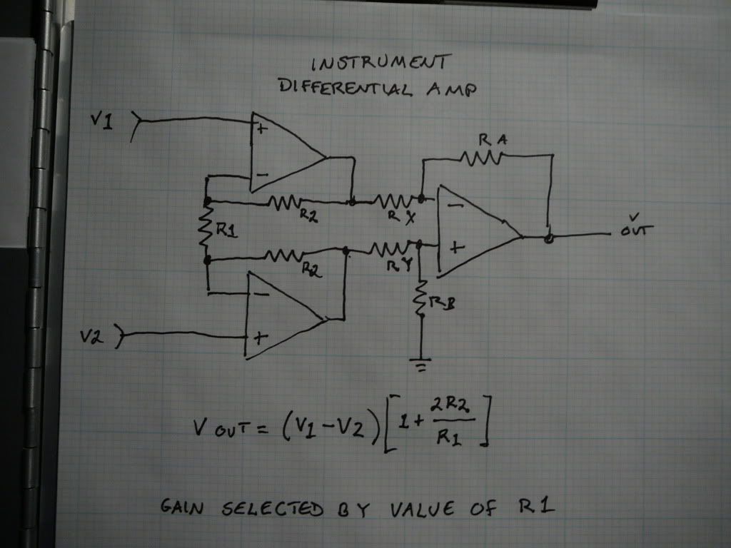
OK, first picture. A typical Differential instrument amp
|
|
August 26, 2010 by Ralphxyz
|
Wow, thanks mongo. What are/would be the typical resistor values? Ralph |
|
August 26, 2010 by mongo
|
Resistor values can run the range. The voltage divider can be a pair of 10K's. Gain resistor can be a 100K pot. The ones under the amps would be around 100K. the rest can be 10K. The gain is adjusted by the pot but as the gain increases, so does the noise. If the resistors on the final stage are about the same, you gave a little gain there. If the last one to the right (feedback on the final stage) is larger than the other two, gain increases as well. A small capacitor between the inputs of the final stage might also dampen fluctuation a bit. Lots of things to try there. I used all 100K trim pots when I was experimenting because they can be virtually anything from almost zero to 100K |
|
August 30, 2010 by Ralphxyz
|
Well I tried, but never could get dependable, repeatable results. I had to use a 1meg Ω as the gain resistor and it almost worked sorta. I tried a simple differential amplifier using a LM307 op-amp with a 410k Ω feedback resistor. It appears to work great! Using anything less than the 410k Ω was unstable and using a 1meg Ω feedback resistor is real solid but I cannot read a 10# weight which is my minimum. Using the 410k Ω feedback resistor I can read a three pound weight. I'll keep playing, possible I'll try something in between 410 and 1meg but I believe the sensitivity might be lost. I sure have learned a lot on this project, besides learning MCU programming, I had to learn about op-amps and now python to see the results. Thanks so much for the help, Ralph |
Please log in to post a reply.
|
Did you know that using an alternating excitation voltage can reduce the noise in many sensor measurements? Learn more...
|


Copyright © 2013 by NerdKits, L.L.C.

 This circuit generally needs a dual supply with the common ground as reference.
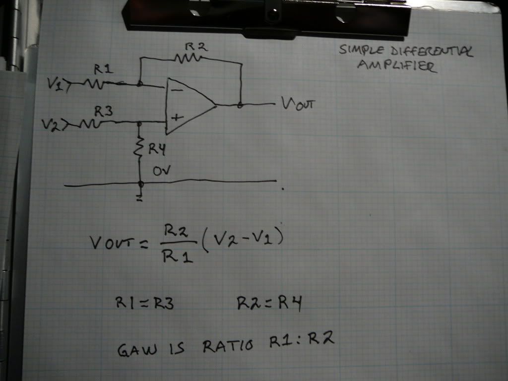 This is a basic amplifier that can be a base for expansion.
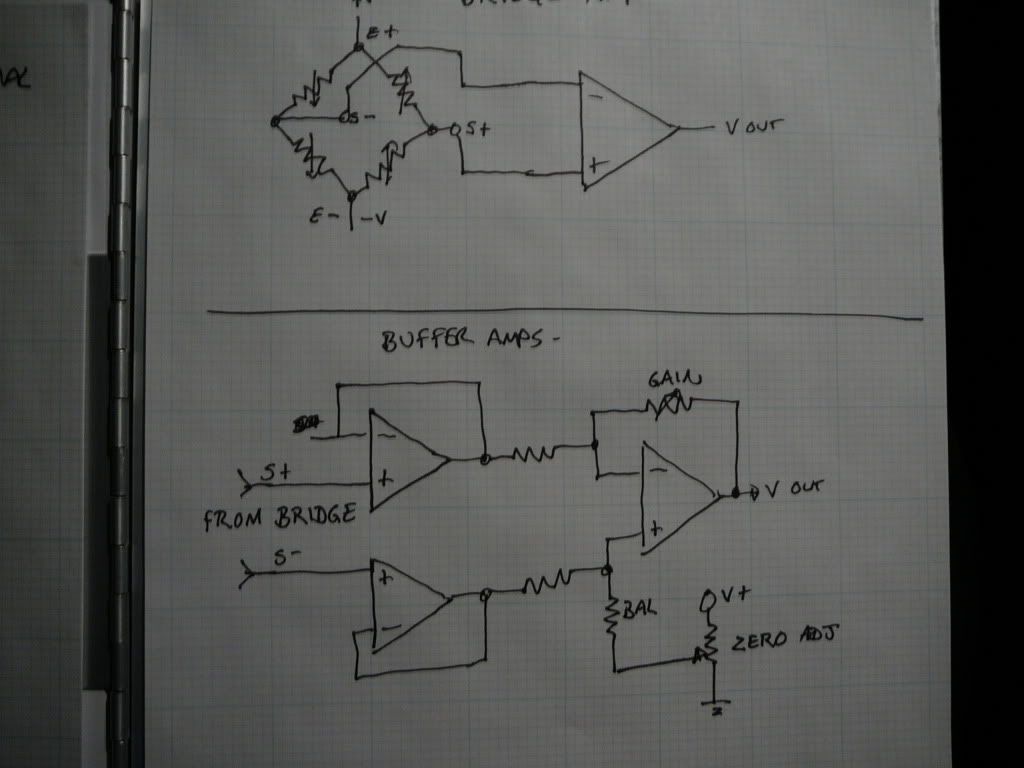 Buffer amps on the inputs prevents voltage feedback going back into the bridge.
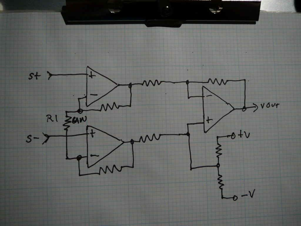 Buffered instrument gain amplifier. Single supply operation. Note the voltage divider for a pseudo reference point.