NEW: Learning electronics? Ask your questions on the new Electronics Questions & Answers site hosted by CircuitLab.
Project Help and Ideas » Strain Gage tied to MCU
|
August 10, 2010 by Ralphxyz 
|
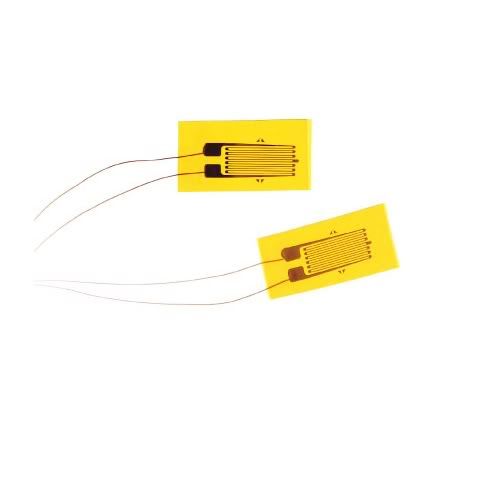
I am really getting dangerous here so I really am going to need all of your help. I need to build a load cell using strain gages from a electronic scale. I have opened up the scale and I have four strain gages with red, black and white wires. They used red and black wires for the power supply so I assume red and black going to the strain gage are power. Well you know what happens with assumptions so my first question is what are these wires? Here is a shot of the controller board Across the top on the left are the power and the two right hand stress gages. On the bottom left the left hand ones. There is a S+ and E+ on the top and S- and S+ on the bottom. Now Mike says in the Nerdkit weighscale tutorial that S is sense and E is excite. This makes sense but he has four wires connected to a wheatstone bridge. Do you think I could hit the strain gage with 6 volts and see a voltage on the white wire when the strain gage is under load? Here is the strain gage (1 of 4).
Now another question, will I need to use all four strain gages in my load cell? I suppose I could stack them and using the tempsensor program code add the individual values or do you think just one would be enough. They certainly appear to be stout. The scale had a 0 - 400# range which I will need. I could not believe the price of load cells and none that I found give me the 0 - 400# range so I might just have a comercial product here if it works as I have planed. I sure appreciate your comments. Ralph |
|---|---|
|
August 10, 2010 by mongo 
|
From the looks of the circuit board, I would be inclined to think that the little cell is actually just have of a Wheatstone bridge and it takes two cells to make a complete bridge. If this is the case, then two pairs make up two bridges and they are balanced out in the circuitry. The load cells that you would find that handle 400# are expensive. There is a way to use lighter units but it involves mechanical leverage and multiplication to do the job. If you have a 10:1 leverage multiplier, you can get away with a 40# cell. |
|
August 10, 2010 by mongo
|
Additional info... The little cells are probably two strain gauges in series. The sense wire would be the junction between the two. Typically, they are mounted to the substrate so that when a load is presented, it causes one strain gauge to stretch across a known point while causing the other one to contract across the same point or a mirror of it. Strain gauges are really just a very thin conductor that runs back and forth from end to end where the middle section over a number of passes are subjected to the strain being measured. As the filaments are stretched, even though very very slightly, across a lot of them the stretch adds up. This increases the resistance between the terminal connections. The opposite also applies, as they are compressed, whereby decreasing the resistance across the circuit. By putting them in series, you have a voltage divider that acts a lot like a potentiometer, which uses deflection of the substrate in place of a wiper and knob. A full load cell has at least four strain gauges in the typical Wheatstone bridge configuration and gives a differential output rather then a voltage output in reference to the supply voltage. The differential output is more stable and more tolerant of voltage fluctuations. Generally, the higher quality cells also incorporate temperature compensation and distortion compensating strain gauges alongside the rest of the setup. Wheew! I hope it makes sense... I'll add a sketch to give it a visual reference if you like. Here is a sample of what strain gauges look like:
|
|
August 10, 2010 by Ralphxyz
|
Thanks mongo, what little cells are you speaking of? Here is a side view of the strain gage. As you can see the center is raised and would be compressed to produce the strain.
What about the three wires? There is a Quarter Bridge that uses three wires but all of the illustrations show just one strain gage with matching resistors. The scale supposedly measures 0 to 400# so that is why it is of interest to me. There is no lever on/in the scale so all four strain gages are just being compressed. I'll see if I can get some readings with my multi-meter, what should I look for? Ralph |
|
August 10, 2010 by mongo
|
Could be just a single strain gauge and a resistor network just as easily. I can't really tell from the picture. If so, yeah, it would take all four to make a complete bridge. It makes some sense though as the "cornering" would be more consistent. That is when you place a known test weight at each corner one at a time and see if they all repeat. Even then, there would still be 3 wires, just as if they were two strain gauges in each. The little cells are like the picture showed... but now I don't see the picture... The little bump is the load point and the wide area around the outside is the support. There is probably a little difference in elevation between the center and outer edge. When used like this, there is no need for levers or other mechanicals. They are direct reading. They can likely handle twice the load they could ever see. In another lifetime, I worked on scales and balances. Some so sensitive they could weigh down to 10 micrograms. (that's like weighing a hair). They worked on a different principle altogether (magnetic levitation and differential capacitance) but the industrial scales used the good ol' load cells. Some use a single cell like in the Fairbanks platform scales, some use four like the Toledo and others. Some are custom built and fit right on the legs of a silo but that's a whole different thing altogether. |
|
August 10, 2010 by mongo
|
BTW,,, Most strain gauges I worked with were in the area of 300 ohms. (or was it 30?) |
|
August 11, 2010 by Ralphxyz
|
Great, thanks once again. Now re: 300 ohms or 30 ohms, between where/what? each strain gage has three wires Red, Black and White. Where would I start looking red to black, black to white? I'll try to get some live measurements I'll solder some leads onto the circuit board. I started probing around with my $12.00 Radio shack multimeter and I do not see any voltage between the red and black coming from the strain gages. I was hoping the 8 red and black were power and the 4 white wires were the Excite+, Excite-, Sense+ and Sense-. The scale is powered on with weight being applied so there has to be a on off function coming from the strain gages. Well I'll keep probing. Here is a shot of the full scale:
Ralph |
|
August 11, 2010 by mongo
|
Ahhh.. I see. Gotchya on the 9-9 thing. It has been a long time since I played with strain gauges so I am working from mostly a rusty memory. They range from around 120 ohms to 350 ohms in most cases but there are some up to 1K as well. These are raw strain gauges by the way, unmounted and no resistors in the circuits. All I can suggest is to see what you have between the black and red wires and that all four of them are the same. I think there is some pretty good info at www.omega.com, that has lots of information on strain gauges and how to use them. |
|
August 11, 2010 by Ralphxyz
|
I have some Ω readings between the wires. These readings really look like a potentiometer's readings. I can put some pressure on a strain gage with a C clamp to see what the readings are under load. I would really like to just tie the strain gages to the Nerdkit and not use the scales PCB or electronics. I wonder if I'll get a variale voltage off the white wire like a pot's wiper? Ralph |
|
August 11, 2010 by Ralphxyz
|
Oh yeah, Omega has some great stuff but nothing I have seen so far addresses 4 strain gages using 3 wires. I have found a 3 wire Quarter Bridge using 3 wires but only one strain gage in the Wheatstone bridge. I am still looking but thanks for your help so far it really helps me understand what the heck I am doing. Ralph |
|
August 11, 2010 by mongo
|
I have been looking at various specs. I think the four disks you have would more accurately be describes as transducers. They seem to use a single strain gauge and probably a little balance network or something similar. They most likely give a specific voltage at the 'signal out' wire, which is likely the white wire. The voltage should be relatively linear and something like 10mV/Lb or similar. With four individual units, the outputs are probably averaged in the circuit to give a constant result regardless of the position of the load being weighed. Opposite corners probably offset each other so if the weight is placed closer to one, the other subtracts the difference. |
|
August 12, 2010 by Ralphxyz
|
Exactly what I was hoping to hear!! I "should" be able to tie the white wire to the ADC on the MCU and average the voltage. If I get 10mV/Lb I would not even need a OP-AMP. For my specific project the load would be always linear (narrow straight line) so I might be able to make up 4 load cells. I paid $24.00 for the scale so I am looking at a very low price 0 - 400# load cell. Mongo thank you so much for your time and help. Now of course I have to figure out how to transfer the load from a cable to the transducers. Ralph |
|
August 12, 2010 by Ralphxyz
|
Okay I finally built up enough nerve to attach some wires to test what was happening. Between the Red and Black I get a steady .735v. Between White and Black I get a variable tenth of a mili volt scale. For 20# .5mv 30# .6mv 40# .7mv and for 70# I got .8 mv. This is only reading one transducer. I am weighing dumbbells on the glass scale so I have to be careful. I am getting a bouncing reading when I try to weigh myself between .4mv to .7mv I do not know what this means. I'll wire up the other transducers and hitch to my Nerdkit. Possible with a tenth of a milli volt I'll need some sort of amplification. Any one have a simple op-amp circuit I could use? I have some 741 and some quad op-amps that I have never wired up. I have multi sensor code from the tempsensor project so I'll be able to read the four transducers maybe then I can figure out the logic of what I am seeing. Anyone have any insight or words of wisdom? Ralph |
|
August 16, 2010 by mrobbins (NerdKits Staff) 
|
Hi Ralph, Based on the information you've provided, this is my best guess as to what each strain gauge is:
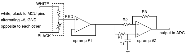
I don't know whether the variable part is between black and red or white and red, but it doesn't really matter, so I just placed it arbitrarily. White and black are the "excite" wires, and red is the "sense" wire. We did recommend the AD620 instrumentation amplifier for our Digital Weight Scale project, but in that case, we had two sense wires. We had to read the voltage difference between the two sense wires. However, in your case, you only have one sense wire, so there's no real "difference" to be taken -- you are just taking the difference with respect to a calibrated zero position. This might actually make the circuit easier! If you get a chance, can you tell me the exact make/model of the digital scale that you have? Other people have had similar questions about the 3-wire strain gauges, so maybe if we get some free time here at NerdKits we can re-do the weighscale tutorial with these strain gauges. As far as how to go about reading from it, here are two ideas at least in "sketch" form: Potentiometer + instrumentation amplifierHave a potentiometer connected between +5 and GND, set to roughly 50%. Then follow along with our Digital Weight Scale project, with the potentiometer wiper terminal as the second "sense" wire. This will work, but it's probably overkill to use the instrumentation amplifier in this situation. DC-coupled op-ampsIt's possible to amplify a small DC voltage using op-amps dealing with only DC. However, doing it in a single-voltage-supply way is not trivial and adds a lot of parts, since your signal should be centered around 2.5V, not ground. You can pursue this route, but you will basically end up re-creating an instrumentation amplifier! In any case, that's fine, but I'm going to jump forward to what I think is the right way to do it. AC-coupled amplifierInstead of worrying about voltage offsets and subtraction, you can use AC signals to actually solve this issue elegantly despite the fact that your signal isn't centered around ground. Here's my circuit sketch:
At the output of op-amp #1 (which is simply a voltage follower, or buffer), you'll have a square wave centered around 2.5V, whose amplitude will vary with the compression of the strain gauge. Then, choose R1 and C1 to form a time constant much slower than the square wave -- perhaps R1 = 100K and C1 = 10uF, for a 1 second time constant. The non-inverting input of op-amp #2 is now automatically centered at the average value of the square wave! R2 and R3 form an inverting amplifier, so overall, the circuit will have gain of -(R3/R2). I will toss out the values of R2 = 1K, R3 = 100K as a possibly-reasonable starting point for you. Then, the output of op-amp #2 goes to your ADC, and you sample the high and low points of the square wave and subtract in software. This is what we did in our project video, so you might actually be able to use our digital weight scale code as-is. If you need more gain, you might have to string together extra amplification stages instead of just increasing the ratio R3/R2. That's because of the "gain bandwidth product (GBP)" of the op-amp. For example, a 1MHz GBP means that if you're trying to amplify by a factor of 100, the bandwidth drops to about 10kHz -- which might be close to your square wave frequency. Hope that helps get you pointed in the right direction! Mike |
|
August 17, 2010 by Ralphxyz
|
Boy, this is unbelievable I am sure getting a education on the Nerdkit forum thanks so much. I sure wish I knew what I was doing. The forum help is just amazing. Between Red and Black I get a steady .73 volts while under varying load. Same for Red and White (.73 volts). White + and Black - I get variable tenth of milivolt depending on load. This is probable the scale I got from Amazon. I got a My Weigh élite but I paid $24.00 and this one list at $21.00. Mind is also green not black. I see there is a $16.00 My Weigh scale also, I would assume it uses the same technology but you just never know. Now Mike you say "White and black are the "excite" wires, and red is the "sense" wire." On the pcb the red wire is labeled S+, S-, E+ and E- Looking at the bottom: S+ goes to bottom left. S- goes to bottom right. E+ goes to top left. E- goes to top right. This is such a fascinating thread I sure hope others are enjoying it and getting a lot out of it. Just for the record these are the other threads I have in conjunction with this thread. Thanks again to everybody, I literally could not do this with out your help. Ralph |
|
August 17, 2010 by mrobbins (NerdKits Staff)
|
Hi Ralph, I am guessing that the 0.73 volts is coming up because it's roughly half of a 1.5V battery voltage, although there are other possible explanations. I'm a bit confused because I was assuming that you were going to disconnect the strain gauges from the original scale's electronics board and mechanics, and just use it totally independently. If I were you, I would de-solder one of those strain gauges (red, black and white). Then -- on a totally separate system, like your NerdKits breadboard -- connect black to ground, and white to +5. You should then measure about 2.5V from red to black wires. In this configuration, the three-wire half bridge is acting as a voltage divider, with a voltage ratio on either side (red to black and red to white) that is equal to the resistor ratio. If your multimeter has enough digits, you may see a tiny change when you apply force to the strain element. Can you give that a try and see what happens? At that point, I think we'll be working from the same starting point, and my op-amp ideas might make sense. Otherwise, you've got to try to fight/accomodate whatever the scale electronics board is already doing to drive the strain gauge! Mike |
|
August 17, 2010 by Ralphxyz
|
Wow Mike you are asking a lot. My intention as you say is to do away with the scale's electronics. BUT I hadn't buit up the nerve to cut the cord. I agree isolating the strain gage would make things simpler but I was not sure how to power it. Using the Red as the sensor wire is starting to make sense as it is labeled S+, S-, E+ and E- on the pcb. Do you think I can use one strain gage or would I need to use all four? Like mongo had said maybe they use a averaging method in the electronics. Are they making up a Wheatstone Bridge? Where would the S & E plus and minus come from if not? Using a single transducer would be fine with my project idea, I specifically need two strain gages tied to one Nerdkit. All right I can do it, I can cut the cord (after all I delivered three of my children at home and had to cut their cords and they are doing fine). Once again Thanks everybody, wish me luck! Ralph |
|
August 17, 2010 by Ralphxyz
|
Mike the scales power supply is two 3 volt button batteries ( 6 volt). Knowing that will help me connect 5 volts to the white wire, I was a little leery as the highest voltage I see is only .73 volt. Ralph |
|
August 17, 2010 by Ralphxyz
|
I isolated one strain gage from the scale and hooked it up as Mike suggested: Black to ground White to 4.93 volt Reading Red to Black (ground) I get 2.463 volts with no load. When I put a load (@ 50#) on I get no difference I still get 2.463 volts. I can not see the strain gage possible it is not getting compressed I'll rig up a C-clamp to compress it and see what I get. What should I see? should the voltage increase or decrease? Could the change be so small that I need to use the op-amp to increase it enough to see? Ralph |
|
August 17, 2010 by mongo
|
Try red to +, black to - and see if the white wire changes with the load. |
|
August 17, 2010 by Ralphxyz
|
That gives me 4.89 volts without a load there is no change with a load. Ralph |
|
August 18, 2010 by mrobbins (NerdKits Staff)
|
Hi Ralph, I'm not too surprised that there is < 0.001 volts of change. Your C-clamp idea seems worth trying, though of course you don't want to break anything. From your earlier measurements, it sounds like you have a multimeter capable of reading tenths of millivolts (0.0001 volts), and that you saw changes with load previously. Can you make a static second half bridge, such as with two equal resistors, or a potentiometer, or even a second one of your strain gauges, to create a relatively constant supply also around 2.463 volts (Vsupply/2)? If so, then you can try your multimeter on its most sensitive scale between the red wire of the strain gauge and the center tap of this constant second bridge, and see if that relative voltage changes with applied force. Mike |
|
August 18, 2010 by Ralphxyz
|
Mike could you sketch out a schematic on what you are suggesting. I'll need to machine a holder for the strain gage in order to use a c-clamp so that will take a bit. Here are some new resistance readings with the strain gage isolated from the scale. White to Black 2.004 kΩ no load White to Red 1.002 kΩ no load White to Red .999 kΩ under @40# load Red to Black 1.001 kΩ no load Red to Black 1.003 kΩ under @40# load I am getting some variance under load for resistance but I can not see any voltage change, the change would be minuscule at best. White to red appears to decrease resistance under load while red to black seems to increase resistance. Once again thanks so much. I have a really great project in mind if I can get all of my threads answered. I am surprised no one has anything to say about changing a linear stretching motion to compression isn't that a Physics 101 exercise (of course I never took physics). Ralph |
|
August 18, 2010 by mongo
|
I have been thinking about how these are wired in the scale... It is really starting to sound to me like you need all four connected to be a full Wheatstone bridge. It may be much simpler than I originally thought. he square wave concept that Mike mentioned is the same that one of the major manufacturers uses. (Fairbanks Scales) It is a good way to do it but difficult to keep in calibration. It uses an integrator circuit and some other methods to get a linear signal. The bathroom scale seems to be an instrument amp circuit doing a DC conversion to digital out. |
|
August 18, 2010 by mongo
|
A little more info needed here... On the PCB, there are 8 pads on the top row and 6 pads on the lower row where the cells are connected. Can you identify their names all the way across? I can only read a couple. With those, are the three wires to each cell together geographically? Are any of them connected together through the PCB? With that, I can put together a schematic that makes a little sense and maybe get an idea which direction to go here. |
|
August 19, 2010 by Ralphxyz
|
Ok mongo here ya go, I stripped the pcb from the scale.
re: "there are 8 pads on the top row and 6 pads on the lower row where the cells are connected." The first two on the top left are power - and +. You are calling the individual strain gage/transducer a cell correct? Not sure what you mean by "are the three wires to each cell together geographically" But cell 4 is the top left on the PCB 4B, 4R and 4W which on the scale is the bottom left cell looking at the back. re: "It is really starting to sound to me like you need all four connected to be a full Wheatstone bridge" That is what it would appear to be I could only find a 3 wire quarter wave bridge using a single strain gage with some critically matched resistors. I would suppose the 4 cells would be critically matched, or there might be some compensation on the PCB, I just do not have any idea how to wire it. to start testing. Ralph |
|
August 19, 2010 by mongo
|
Geographically was meant that all three leads for each unit are together as a group.It appears to be so. It sure looks to be four elements of a Wheatstone bridge. The active elements are between the red and white wires. The black wires appear to be a temperature compensation network. The red wires are Excitation and the white wires are Sense. E+ looks to be the power supply, E- looks to be common ground. I see S+ for the top two white wires and S- on the lower two white wires. The black wires appear to be connected corner to corner and seem to be used as heating elements as they are connected across the power supply in series. After all, resistors are just another way of generating heat. Some cells do have heaters to maintain a stable temp and compensate for other variables that can happen in these circuits. I'll draw up the schematic and post it shortly. |
|
August 19, 2010 by mongo
|
OK, here is a quick sketch of what I can extract from it so far. Each little disk appears to be an individual element of the Wheatstone bridge configuration. The white wires are the sense leads and connect to a differential amplifier somewhere in the circuit. I think the black leads are just to maintain a stable temperature at the cells to prevent drift. Reading resistance across a strain gauge is really not very easy. Chances are that it only changes a few thousandths of an ohm from one extreme to the other. That is why it is part of the Wheatstone bridge. Across four elements, the voltage differential between the sense leads is accumulated so it can more easily be read into an amplifier circuit. They are offsetting in the sense that if one point has more load than the opposite one, the differential between them remains the same. This makes for a pretty stable weighing system for a minimum of parts.
|
|
August 19, 2010 by Ralphxyz
|
mongo, I believe the Excite and Sense wires are the red ones.
Definitely 1R S-, 2R E- and 3R E+ are so labeled it looks like the 4R S+ label was moved to the right because of that connection point to the left of the label. The other three labels fall directly in line the S+ is offset from the W4 just a bit. Ralph |
|
August 19, 2010 by mongo
|
That would make better sense. Otherwise they would not offset each other if not evenly loaded. It should have no other effect. With that realization, I will revamp the sketch and see how it turns out. |
|
August 19, 2010 by mongo
|
Ok, here it is with the corrections to the terminals.
Sorry bout the blur... I think I moved a little when I pushed the button. |
|
August 20, 2010 by Ralphxyz
|
mongo, thanks for the Wheatstone bridge illustration, I actually understand what you illustrated except for the resistors you added. Would these resistors be critical (1%)? What value would these resistors have? Do they have to match the cells Ω (2kΩ is what I get White to Black )? What is that mark on the 2nd left hand resistor.
Ralph |
|
August 20, 2010 by mongo
|
Ralph, Those are the same as what is shown earlier in the thread. I think they were all around 1K each. Maybe 880 ohms. At any rate, they are what are already in the little disks. 1K for the active element and 1K for the internal resistor. Total 2K. Red wire is at the junction between the two. White wire is from the active element, Black from the resistor. The mark in question was a slip pf the pen. No meaning at all. Remember, it was just a quick sketch while a cat was trying to help. |
|
August 20, 2010 by Ralphxyz
|
Ah, you mean this:
That was Mike's "best guess" of the cell configuration based on the wire readings I gave. So I am going to test in a Full Bridge Wheatstone configuration.
Don't pay any attention to the math which actually should be correct I just got the math when I glommed onto the image from a reference found on the web. I suppose reading S+ and S- I will see something in the millivolt range or possible in the tenths of a millivolt as I was seeing on the scale. Ralph |
|
August 20, 2010 by mongo
|
Yup. Exactly like that, only these have the resistor in series with the active elements and they act as voltage dividers, presumably to keep the signal somewhere near the middle of the power supply range so a differential amp can use the signal better. The differences measured between the S+ and S- leads is larger than trying to measure a single cell and provides a nice differential voltage to measure. You can see where I drew it up with the Excitation and Sense leads are in the middle of the networks rather than the corners.... That is only to keep each cell identified as a unit but electrically, it is still the same. |
|
August 20, 2010 by mongo
|
BTW... I may have gotten the active and passive elements switched. So many possibilities here, but it works the same either way. |
|
August 20, 2010 by Ralphxyz
|
It works, It works, unbelievable it actually works. I have the cells placed back in the scale, with the scales electronics removed. I get a -.1 or -.2 milivolt with no load if I just touch the scale I get .1 milivolt and it progresses up as I press harder on the scale. Pressing hard on the scale I get up to 1.3 milivolts which is around 40# pressure. The S+ and S- appear to be reversed but that could be my wiring but it works. Now I'l try adding the Nerdkit Digital Scale Strain Gauge Weight Sensor code to my MCU. I am sure I will need to use a op-amp to bost the signal for the ADC, I have that thread working also. mongo, thank you so much what a great help and asset you are to/for the Nerdkits forums. Thanks to Mike and everyone that even read the threads and wished me luck (I needed it). Well the next time someone ask about strain gages or a Wheatstone bridge I'll be all over them with my "expertise". This is so much fun, I can not believe I took a electronic scale apart and am connecting it up to my Nerdkit, from there it could connect to my PC. Did ya'll see the recent Bluetoooth thread. Now that would be interesting to have my scale readings sent wirelessly to my pc. I have a project in mind to use the cells from the scale as a load cell but I need to have a good method of changing a linear motion to compression. Thanks again everyone, Ralph |
|
August 20, 2010 by mongo
|
Cool! Now it's just a matter of scaling the signal to an intelligible one that humans can read. Are you reading the differential between the S- and S+ lines for the 1.3mV? I'll draw up a simple schematic for an amp that should work well for you. Just a basic one for the idea but it should get you headed in the right direction. |
|
August 20, 2010 by Ralphxyz
|
I bought some of the OP07 op-amps I could not find any of the AD620s Mike used. I sure could use a schematic, I tried doing a feedback with the LM324N but that didn't work. I did some playing around with the 741 op-amp twenty years ago and had a pretty good handle on op-amp operations but now it is just a blank wall. But I haven't done anything with electronics for the past twenty years, so it is not surprising you know use it or lose it. I looked at the Nerdkits weighscale project code and between that and the tempsensor project the coding "should" be easy. Of course I need to convert linear motion to compression in order to implement my particular project, but just tying a different scale to the Nerdkit MCU and then to my pc is really neat. That Bluetooth module is growing on me. Yes I am reading between S+ and S-, Ralph Ralph |
Please log in to post a reply.
|
Did you know that the sparks present in motors can be dangerous for your microcontroller and other electronics? Learn more...
|


Copyright © 2013 by NerdKits, L.L.C.


 .
. My web server is only up between 9:00 a.m to 9:00 p.m. e.s.t. so the pictures are not always available sorry.
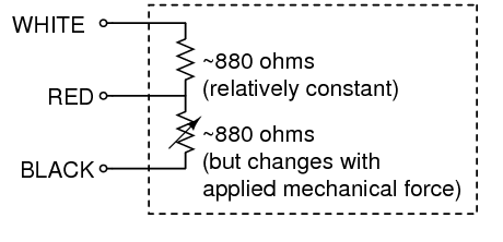


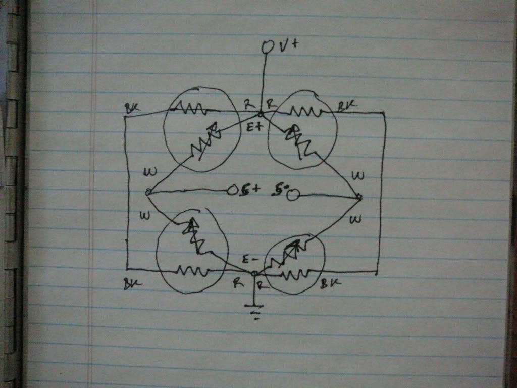


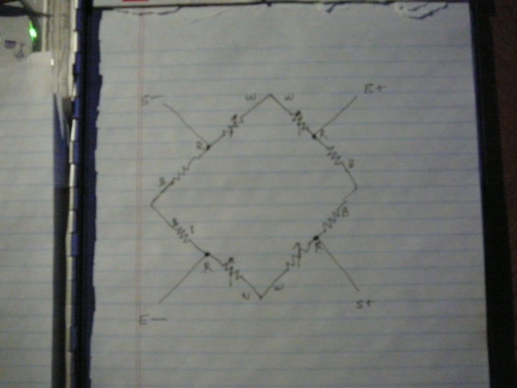 I made the element between the white and red wires the active one in each node but the red/black can also be active in this config. It is still in the Wheatstone arrangement but no longer uses the lines as heating elements as originally speculated.

