NEW: Learning electronics? Ask your questions on the new Electronics Questions & Answers site hosted by CircuitLab.
Sensors, Actuators, and Robotics » Driving a DC Motor in Making or Buying an H-Bridge
|
April 19, 2010 by mosfet |
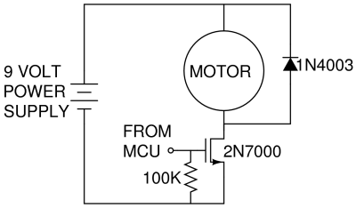
Hi all, I need an H-bridge to run a dc motor both directions. The basics of the H-bridge seem trivial and very cool: H-bridge at Wikipedia. But it seemed less trivial where the flyback diodes should go. Driving a motor in a single direction is simple enough with the flyback diode shorting the momentary high voltages across the motor: But with an H-bridge, the application of flyback diodes seemed less trivial. But I've found this article, and they get to flyback diodes toward the bottom, just before the last image. The arrangement of flyback diodes is cool; try going through the through the thought experiments of the motor being turned off from running each direction. Even cooler, is that it seems the mosfet's built-in diodes handle this. Now to actually implement this, I'm looking for assistance on what components to buy. The article mentions that "N-Channel Mosfets are much cheaper than P-Channel Mosfets". So does it make more sense to buy a pair of P-Channel mosfets or just an H-bridge chip? I plant to PWM my motor at 12V. It's unlabeled and a little bigger than a 35mm film canister. It's very weak at 5v, but is decent at 12V. Brick source = 12.1V, while running motor voltage drops to 10.7V, using 185ma. ~2W. How does one select an H-bridge chip? The Intersil HIP4082 seems more than sufficient, based on voltage and current: http://www.intersil.com/products/deviceinfo.asp?pn=HIP4082&js=n http://www.intersil.com/data/FN/fn3676.pdf But what's going on on page 3, "Typical Application (PWM Mode Switching)"? It looks like |
|---|---|
|
April 19, 2010 by mosfet |
Well, that was a big oops. An accidental keystroke posted my message while I was editing the title and not done with the body. Ah well. So, for bidirectional DC motor control, is the Intersil HIP4082 a decent choice? (given my motor info mentioned above). And I'm confused by the "Typical Application (PWM Mode Switching)" illustration on page 3 of the pdf. It looks like, connected to the load, there are somethings/mosfets(?) outside of the HIP4082 chip? I was hoping an H-bridge chip incorporated the 4 mosfets, and that just a pair of leads on the H-bridge chip would go to the pair of motor leads, giving you bidirectional motion. Any help? |
|
April 19, 2010 by mosfet |
I've also stumbled upon the TI L293 and L293D and they seem like a simple lower-cost option: http://focus.ti.com/lit/ds/symlink/l293.pdf The L293D seems so appealing I'm about to buy one. The block diagram is on page 2 of the pdf. Here are my newbie guesses: It seems pin1 enables half-H's 1 & 2 to function. Half-H 1 seems to be controlled via on/off signal on pin2, creating output on pin3 of Vcc2-or-0V to motor lead. Half-H 2 seems to be controlled via on/off signal on pin7, creating output on pin6 of Vcc2-or-0v to other motor lead. Please correct me wherever I'm clueless or off-base! Also, it appears one must use external flyback/protection diodes with the L293. But it seems the L293D has flyback/protection diodes included. "Output Clamp Diodes for Inductive Transient Suppression (L293D)" The pdf makes it seem Vcc2 is the output voltage/supply, for all 4 Half-H outputs. Yes/no? I'm confused, because this page makes it seem that Vcc1/pin16 is the output voltage/supply for Half-H's 1 and 2, and that Vcc2/pin8 is the output voltage/supply for Half-H's 3 and 4. Does this contradict the pdf? And of course, what exactly is Vcc1 for? For others' benefit, could someone post the L293/L293D's block diagram and logic diagram? I don't have a site to host captured pics. Any help is greatly appreciated! Thanks! |
|
April 19, 2010 by Rick_S 
|
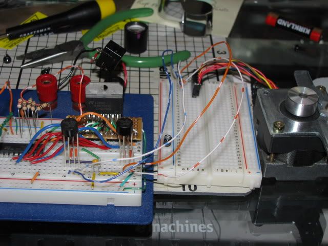
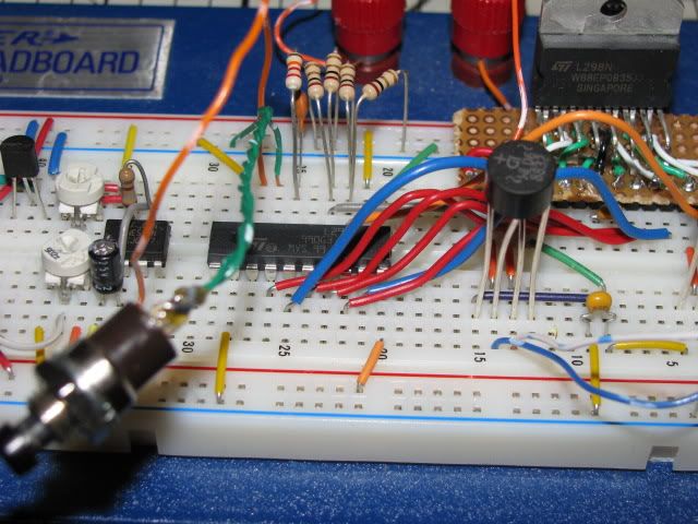
I've been messing around with L298's. As a matter of fact, I have one setup right now that I've been playing with stepper motors with. The L298 is a dual h-bridge with up to 2 amps output. My first test was to drive a simple hobby motor which worked great. Since then, I've been playing with steppers driving the L298 with an L297 and a 555 timer. I'm just experimenting right now to get a feel for the chips. So far, I'm pleased. I got the L298's from a guy on e-bay for $4 each shipped. Here's some pics of the setup.
I haven't tried the other bridges you mentioned, but this one works well. Rick |
|
April 19, 2010 by Rick_S
|
Oh, BTW, you aren't crazy, the website you referred to and the datasheet do contradict each other a bit, but then the datasheet contradicts itself on pages 4 & 5 where it says And then in the table on page five says 4.5 min to 7v max. It appears that VCC1 should be 5v for the logic portion of the chip and VCC2 would be the voltage for driving the motor(s). Rick |
|
April 19, 2010 by Rick_S
|
Here's another link on that site that seems to confirm my hypothesis. :) |
|
April 19, 2010 by mosfet |
L293/L293D: Quadruple Half-H Drivers. Bi-directional drive of 2 DC motors, or use for steppers, or... And the PDIP package easily plugs into the breadboard.
After seeing a couple other pages on the L293/L293D, it seemed that Vcc1/pin16 was just logic power to the chip, and that Vcc2 supplies output voltage to motors for all four Half-H's. And that matches the other link you posted. (note 3A/3Y/4A/4Y can drive another bi-directional DC motor)
Another info source: The L293 Dual Bridge Motor Driver IC Pinouts
The contradiction within the pdf is also in the newer version of the product (w/diff part number), but now I see that the values are different because the 36V is the absolute max for Vcc1, and 4.5-7V is the recommended range. So I just bought a couple L293D's off eBay for $6 shipped for the pair. I'm dying to try the L293D out, as it seems like it'll be so easy to bi-directionally drive my DC motor. |
|
April 20, 2010 by Rick_S
|
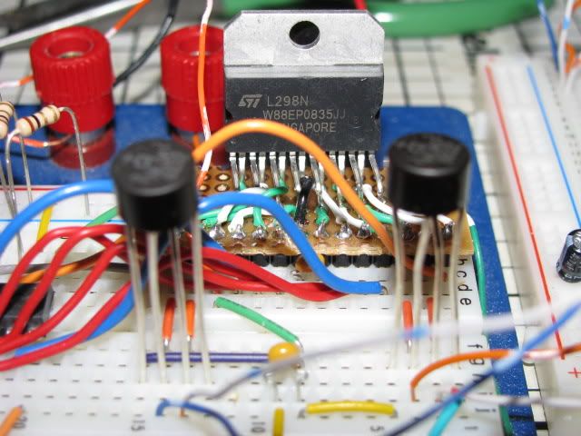
It does look like a nice chip for applications up to an ampere of current. I had looked at the L293 equivalent at sparkfun (SN754410) before getting the L298. I wanted to use it for not only controlling DC motors but primarily steppers. The L298 has current sensing outputs that can allow you to monitor and control the power output to the motor. If it weren't for the marriage of the L297, which uses the current sense and modifies a PWM signal to control output current, I may have opted for the L293 as well. I will agree with you also that the form factor of the L293(D)'s is much easier to deal with as well. I had to get creative to breadboard my L298 as you probably noticed in the photo's. :) BTW, what are you building?? Anything interesting?? Hope it goes good. Rick |
|
April 20, 2010 by mosfet |
Yes, I saw your proto/perf(?)board soldering to get your L298N breadboardable. I haven't done much soldering yet, so I'm glad the L293D seems to meet my power needs. I think the L293 is rated up to 1A continuous, but the L293D (with protection diodes) is only rated to 0.6A/600mA continuous. But the L293 replacement, SN754410 (that you mentioned), has the protection diodes and* is rated to 1.1A continuous. I'd have gotten SN754410's had I known, and I still may. They're $2.50 shipped on ebay (4 for $9.99). When needed output is higher than a chip can offer, I've seen IC piggybacking on ladyada's site to ~double output, just soldering one IC on top of another, pin-to-pin, pretty cool:
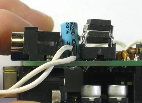
For basic stepper operation, does one just energize the coils in order, for a ~millisecond each? And for low torque apps, doesn't the aligned permanent magnet hold the unenergized stepper motor in place? So your L298N senses current to each coil and outputs 4 signals (0-5V) back to the MCU? Or the L298N itself reads/uses the current sensed? What's the reasoning? Current indicating load, thus changing PWM output power? Did you put a capacitor across ground and power into your L298N? How do you size these supply storage caps? And what are the pair of thick hockey puck devices on 4 tall leads on the front of your breadboard? I'm looking to PWM drive the carriage motor on a dismantled inkjet printer to get controlled linear motion via the timing belt and shaft linear guide. Couple options on what this turns into. I also want to drive some steppers for fun. These quadruple Half-H's seem sooo handy! |
|
April 20, 2010 by Rick_S
|
The control output of the 298 is a voltage reference based on the current output of the bridge I believe it tops out at around 2v. There are two controls one for each bridge. The L297 reads this control and varies the on time of the pwm signal it drives the enable line of the bridge with. So by changing a few components, you can set it up to drive a motor efficiently. Steppers are relatively simple to drive, you just sequence the different phase coils in order. The nice thing about the 297 is it does all this in itself and just needs a pulse to increment the motor. Right now I'm driving it with a 555 timer. The 4 hockey puck looking devices are bridge rectifiers (4 diodes in a single package). Normally used to turn AC into pulsed DC. However, here I'm using them as the flyback diodes. |
Please log in to post a reply.
|
Did you know that talking to the microcontroller over the USB/Serial link is easy under Windows, Linux, and OS X? Learn more...
|


Copyright © 2013 by NerdKits, L.L.C.


 "Vss = Logic Supply = 4.5V to 36V. Vs = Motor Driver Supply = Vss to 36V"