NEW: Learning electronics? Ask your questions on the new Electronics Questions & Answers site hosted by CircuitLab.
Basic Electronics » Limitation of a battery on the NerdKit
|
March 05, 2010 by Shanytc |
I Was playing around with the amazing NerdKit, and I noticed that there is no more power to run the circuit anymore (battery connected to the voltage regulator).. I plugged in the USB's +5V (from the nerdkit) to the + red terminal on the breadboard (connected to the MCU) and everything works just fine, program is running fine. Disconnected the USB, connected the battery to the Voltage regulator.. nothing! I than took my multimeter set it to DC-V and measured the battery, i got a reading of 6.5V. So.. since I'm newbie, I guess I missed something here? is there a drop of voltage elsewhere when I connect the battery to the circuit? (circuit is the same as in project 1 in the pdf) thanks! |
|---|---|
|
March 05, 2010 by Shanytc |
Here is the simple circuit, in case someone wants to see the connections: http://i46.tinypic.com/11sh7r6.jpg
|
|
March 05, 2010 by BobaMosfet 
|
Shanytc- Batteries can be deceptive. Here's why- when you measure your voltage across the two terminals of the battery, using your meter, you are measuring it with no current load attached (hardly any current is going through the meter). As such, you see all the potential (6.5VDC). Once you connect your circuit across the battery however, your circuit requires more current than the battery can deliver-- as such, it "collapses" because it cannot supply enough. If you take your battery again, as you did in the beginning, and just leave your meter attached, do you see the voltage slowly waver and then drop, waver and then drop? It may take awhile to see. I'd replace the battery. BM |
|
March 05, 2010 by BobaMosfet
|
Shanytc- My assumption, because you did not say, is that your battery is 9VDC (What comes with the kit). If you are using a 6.5V battery-- it doesn't generate enough voltage to get through the LM7805 regulator. The LM7805 requires input to be about 2-2.5V higher than output. Just covering the bases. BM |
|
March 05, 2010 by Shanytc |
Hey BobaMosfet, Thanks. Yes, I use the battery that came with the NerdKit. Though (Since I'm a newbie) what I wander is this: Since Battery (9v, now its 6.5v) goes through the voltage regulator (VL), it will output a 5v to the entire circuit. Since, charge flows from Battery -> VL -> circuit (into the MCU), than my logic states that, as long as the battery is >= 5v than all should work, because it still pumps enough current for the circuit ? |
|
March 05, 2010 by pbfy0 |
that doesn't work because the voltage regulator needs about 7 volts to get a good 5 volts output. |
|
March 05, 2010 by Shanytc |
Thanks pbfy0! |
|
March 06, 2010 by Shanytc |
I was wondering, I've got a lot of cellphone power supplies, which convert 220V AC to various DCV (i.e 5v, 5.7, 6.7..etc), For better example: I got a 200V AC to 5V DC 1.0A (max) power supply. Now, I wonder.. to power up the NerdKit without damaging it (too high current), what is the best power supply specs I can use safely (other than the PC USB)? That way I won't have to use 2 USBs (flashing / power) from my pc and use a outlet power supply? or is it not recommended at al? |
|
March 06, 2010 by BobaMosfet
|
1 Amp is a lot of current in terms of what your nerdkit needs. In most cases, the nerdkit by itself will use less than 200mA (and in many cases, less than 100mA). the LM7805 regulator is a good thing to use for a variety of reasons
However, if you're transformer (which is what your cellphone power-supply is -- in fact any of these walwort or power-supplies are just transformers with a few additional components) outputs just 5VDC, then you obviously can't go through a regulator. You still need to protect your circuit from the transformer by using a diode and a decoupling capacitor . This will prevent current and voltage transients and polarity protection. Beyond that, you should use a meter to measure the voltage from the transformer (BEFORE connecting it to your circuit) to see that it is not too much or too little (irregardless of what the sticker says- and also to make sure it isn't bad). Measure it again after you have a load on it, to see if it is 'stiff' enough to support the load. BM |
|
March 06, 2010 by treymd |
Cell phone chargers, many of them, are ideal since they are regulated already, (using something similar to the LM7805). If you can find one between say 5-6 volts it probably is all you need for power. Unregulated wall warts, and to be on the safe side, assume that they all are, do not have that regulator and if they are rated around 7ish you could run them into the 7805 and then into your MCU. The 7805 will get hot and I imagine that the difference from your input to 5v will dictate just how hot it gets. I've done some peering at power supplies and it seems that the regulators are ALWAYS attached to a heatsink, so keep that in mind. Do not be alarmed if the 7805 gets hot, it is made to. You can use a heatsink if you are afraid of meltdown. The regulator for my treadmill was actually connected directly to the frame of the treadmill and gobbed up with heat sink compound. |
|
March 07, 2010 by Rick_S 
|
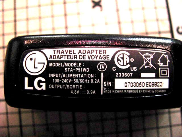
BobaMosfet said: Quote: While many wall-wart power supplies are exactly as you described, there are many cell phone chargers that are much more elaborate than that. Quite often they are small switchers and do provide a constant regulated output. And while all switchers do have transformers, they are hardly what one would consider a normal transformer for dropping 120-240VAC down to 5VDC at 1A. For instance, I have an old LG phone charger rated at 4.8VDC 0.9A
You would not be able to place a transformer capable of dropping 120VAC down to 5VDC in that little box with diodes to rectify it and be able to supply nearly an amp of current. Instead it is a switching power supply filtered and regulated.
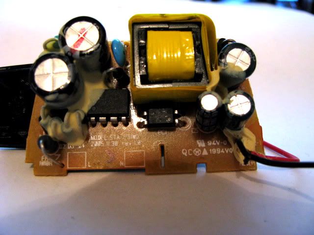
While this does have a transformer, it is much too small to provide all that power itself. Instead, it is bombarded with pulses from the controller chip that if held constant would melt it down. These pulses give it an output that is considerably higher than it would be constant duty. Its output then goes on through a grouping of filter caps and other SMD circuitry on the underside of the board before reaching it's final output. Now, on to your final statement: I AGREE 100%Rick |
|
March 07, 2010 by BobaMosfet
|
Rick_S- I apologize for my generalization. There have been advancements. However, I need to mention a couple things you've stated: I didn't say 'diodes', I said 'a few additional components.' And incidentally, you can do the aforementioned with a step-down transformer and some additional components. Ignoring losses for simplicity sake, we can restate the Law of Conservation of Energy in equation form: Since the transformer is transforming across AC potential, the voltage appearing across the secondary winding is AC (as shown in the calculation above). Following rectification, and ripple-rejection, we end up with 6.89VDC at 4.875amps. Which is within the 48Watts the charger shown is rated for. I'd like you to explain this one further since inductors, particularly at these low frequencies, resist VAC change (reactance), and appear as a short to VDC. If you'll attach clear pictures of both sides of the circuit board so I can see the part numbers, I may be able to get the appropriate datasheets and see how this charger works exactly. BM |
|
March 08, 2010 by Shanytc |
First of all, I gotta say, thanks :D Although I understand none of what you talk about regarding to the wall-wart concept/design, I figured out why my battery dropped fast! In my circuit design, I connected my battery to a 3 way (as shipped with the nerdkit) switch, and connected the battery's + and - terminals to the switch, instead only the +, this caused a short when the switch was off and caused my battery to drain fast! (+ connected to the -). that's why I didn't understand the fast drain, and I thought it was the circuit who caused it.
|
|
March 08, 2010 by Rick_S
|
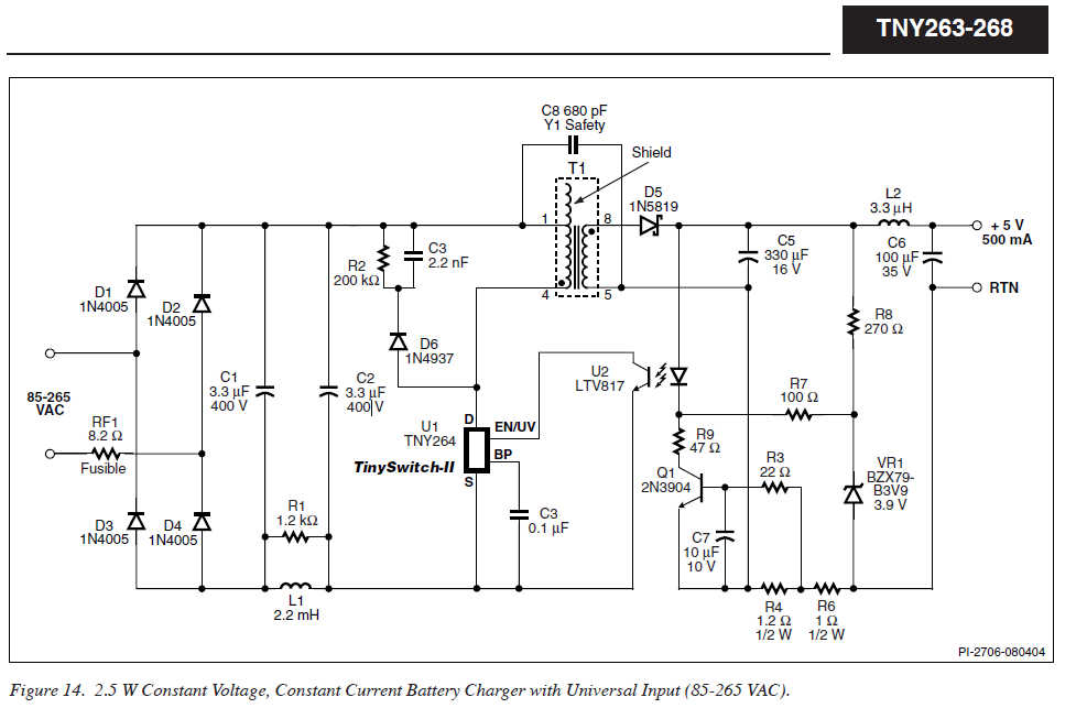
I agree, you didn't say diodes.. However, many of the wall-wart type non regulated adapters simply use diodes in a bridge with a filter cap or two for their AC-DC conversion. (I've ripped apart my share of them) :D That was why I used them as an example of the "few additional components". Also, I'm not saying you can't get a transformer that will do the conversion in and of itself, just that from my experience, a transformer capable of providing nearly and amp of current would be much too large to fit in a small housing such as the cell phone charger I provided for reference. That charger is a switching power supply. The onboard switcher IC is part of the Power Integrations TinySwitch II Family and is a TNY265PN. It does most of the work on the board monitoring input and output, and keeping everything happy. The additional components on the board are simply as such: On the input side, some diodes setup in a bridge with capacitors and coils to convert the AC to DC for the chip and smooth it out some. A small transformer that does the basic voltage drop. Then the output monitoring feedback and filter components. This schematic taken directly from the datasheet is very similar to the charger circuit on the board I'm speaking of.
If I stepped on toes or came across like an a$$, I apologize, sometimes I come off tactless -- (Just ask my wife about that ;D ) Rick |
|
March 08, 2010 by BobaMosfet
|
Rick_S No, no, you were fine. That's why I asked for clarification- I couldn't make out a part number. I like being able to discuss it with you so everything gets answered. Thank you very much for the schematic information on this-- it's quite fascinating. They are operating the switcher at a much higher frequency than I would have thought, so that answered the inductive question I had. The other items really are protective items (clamping, ripple-rejection, power-control, thermal overload, and phase). I have to say I'm really impressed with that TNY265 FET... I'm going to rework some of my designs around this, it's fantastic! BM |
|
March 08, 2010 by Rick_S
|
It is an amazing little bugger. You'll find these quite commonly in cell phone chargers. They really make great inexpensive supplies for the projects. |
|
March 08, 2010 by mongo 
|
Yeppers!!! That's one of the reasons they suggest you use the battery, especially if you are new to this stuff... Just in case there is a wiring oops, things don't go acting funny or the magic smoke gets let out, losing all functionality. Everything works on magic smoke. It will do some really neat things and can be trained to do many wonders, but if you give it a chance, it will escape and things stop working. |
|
December 14, 2010 by danuke 
|
what about powered breadboards? http://www.circuitspecialists.com/prod.itml/icOid/9651 I think that they would be good for learning about electronics/circuits and all, but I don't know about the MCU. The one above has a 5V supply and adjustable + & - 0 to 15V supplies. |
Please log in to post a reply.
|
Did you know that you can connect to certain car computers via the OBD-II port with a microcontroller? Learn more...
|


Copyright © 2013 by NerdKits, L.L.C.