DIY Meat Thermometer with Predictive Filter

To passionate chefs, cooking is an art. Knowing exactly when a cut of meat is cooked to perfection requires knowing your meat and your grill. But with a little bit of technology, we can build a digital meat thermometer, and use digital signal processing techniques to get a much faster response. This video explains how we can use the predictably slow heat transfer inside the temperature probe to mathematically model the sensor, and ultimately get a much faster response, with a little bit microcontroller computing power!
Warning: undercooked food can make you sick. This device was made to demonstrate an engineering concept, and must not to be relied upon to ensure that food is fully cooked to a safe level.
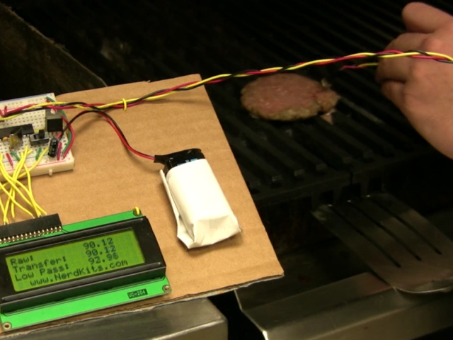
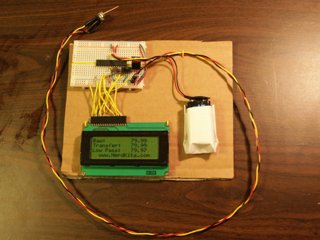
Here are some photos of the meat thermometer system. Click any photo to enlarge:
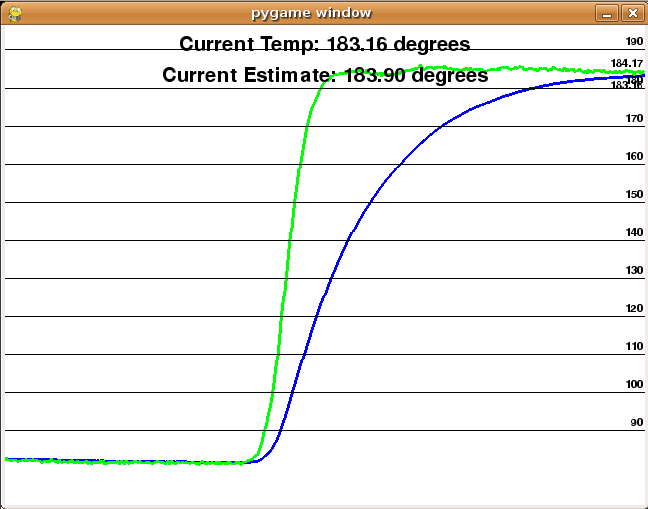
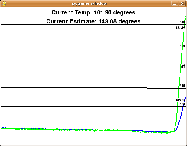
Here are two screenshots of the system results, when the temperature probe is moved from room temperature to hot water. The blue line is the temperature measurement being reported by the LM34 temperature sensor. The green line is the predicted settling temperature after the digital filtering explained below. The green line reaches the top temperature in just about three seconds, compared with about 15-20 seconds for the blue line!
Click any photo to enlarge:
Physical Construction
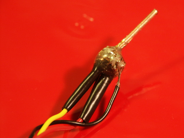
The construction of the meat thermometer in the video seems sort of tricky, and it can be, however the thing to remember is that you want the quickest thermal path from the meat to the sensor, and you also want to protect the sensor from the food. Here is a quick overview of the steps in the video:
Predictive Filter: Conceptual
Lots of systems in nature have what's called a "first-order response", or "first-order kinetics", or a "single time constant response", or have a "single pole transfer function". These are all different names for one basic concept, which is the idea that the rate of change of some quantity being measured is proportional to either the quantity or the difference in the quantity between two places.
In this case, the system is the heat transfer between the tip of the temperature probe and the actual temperature-sensitive region of the sensor integrated circuit. No matter how well we construct the physical device, it will always have mass, and that means that a finite amount of energy needs to be transferred from the meat to the sensor in order for the sensor to heat up. This takes time, and the rate of conduction heat transfer along the probe is proportional to the current temperature difference, which gives us a first-order response.
As we explain in the video, the real key to this project is in understanding that since we know how the physics of the system distorts the sensor reading from the true temperature at the tip, we can use the sensor readings to guess what the true temperature at the tip must be to give that reading.
Predictive Filter: Code
As we said in the video, we are taking advantage of the first order characteristics of the thermal system to "predict" what the actual temperature of the tip is before the measurement settles out to the final value. Wrapping your head around this concept is one thing, but implementing an inverse transfer function in code can be another.
We know from the equation of the first order system that to guess the final value we want to take the derivative of the current measurement, plus the current measurement, and add them together with some scaling that is dictated by what the time constant of the system is. If you were to do this from a mathematical point of view, you could write down the transfer function of the system in the continuous domain, and apply a bilinear transform in order to transform it into the discrete (digital) domain. You would then take that discrete transfer function and find its time domain equivalent, which you could turn into code. This approach would take into account the time constant of the overall system, as well as the sampling frequency of the analog to digital converter (ADC).
However, having the luxury of experimentation, we don't have to do the rigorous math, but instead code up something that looks like what we know the answer should look like and just tweak the parameters until the filter does what we want. (Developing a mathematical model and fitting its parameters to real data is an important part of engineering!) To take a derivative in code, we simply subtract the last two samples, which will give us the rate of change. We will have one parameter 'a' that we will tweak to give us the right response.
Predictive Filter
The function we are going to use will look something like this:
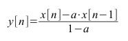
where x[n] is the current sample, x[n-1] is the previous sample, and a is a parameter that we can adjust. (Note that 'a' should be strictly less than one for this equation to make sense.) Notice how the function ends up subtracting the current value minus the previous value, which is the derivative, and weighing the derivative and the current value according to what 'a' is. For our system we ended using an a value of about .99. Your ideal value of 'a' might be different depending on how long your copper wire is, how much epoxy you used, the sampling rate of the analog to digital convertor, and a bunch of other variables. Make sure you experiment with different values of 'a', and observe the difference in the predicted values. It's fun! Note that if 'a' is too high, the system will overreact to a changing temperature and will have "overshoot", while if 'a' is too low, you won't save much settling time by using the filter.
June 18, 2009: If we let B=a/(1-a), Another way to represent this equation is:
y[n] = (B+1)*x[n] - (B)*x[n-1]
y[n] = x[n] + B*(x[n] - x[n-1])
The last form in particular makes it more clear that we're just taking the current value and adding the current slope times some parameter we can adjust.
Low Pass Filter
We also need to implement a low pass filter in software, so we can try to suppress the noise that we inadvertently amplified by using the derivative of the filter. To do this we implement a very simple low pass filter, all it really does is it makes the current sample some combination of the last sample and the current sample, but adding them together with different weights. The more you weight the previous sample, the more filtering you are going to do because in effect this will keep the output signal from changing too quickly. Once implemented in software, the equation will look something like this:
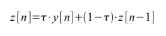
Notice how the current output in the filter is just a combination of the current sample and the previous output. Here the parameter you can tweak is τ. Making τ smaller will give a bigger weight to the previous low passed output, z[n-1]. This will give the low pass filter a bigger effect which will give you less noise, but a slower system. Making τ bigger and closer to 1 will allow your system to change faster, but it will also let all the noise through. Experiment with this parameter and find the trade-off that suits you best.
Linear Scaling
If you look at our code, you will find there is one more function we run our samples through. This is a scaling function that we use to calibrate our sensor. Due to normal heat dissipation paths through our system it is unreasonable to expect that all of the heat makes it through to our temperature sensor. To account for this we put our sensor in boiling water and recorded the highest temperature it read. As expected it was less than the 212 degrees Farenheit of boiling water. We set the scaling parameters to scale the high we recorded up to what boiling should actually be, and did the same thing for freezing water.
Parts List
All of the electronics parts needed for this project are included with our USB NerdKit, including the LM34 temperature sensor chip.
However, you will need a few extra things to build the sensor the way we did: cyanoacrylate (Super Glue), epoxy, 12 gauge solid copper wire, copper desoldering braid, electrical tape, and a soldering iron.
Source Code
If you want to try this project for yourself, go ahead and download the source code. The provided code includes the C code for the MCU as well as the python program we use to do a live graph of the temperature and the predicted temperature. Feel free to modify this code to do interesting things. You could try:
More Videos and Projects!
Take a look at more videos and microcontroller projects!
Comments
|
Did you know that interrupts can be used to trigger pieces of code when events happen? Learn more...
|


Copyright © 2013 by NerdKits, L.L.C.