NEW: Learning electronics? Ask your questions on the new Electronics Questions & Answers site hosted by CircuitLab.
Microcontroller Programming » Turn Nerdkit Display into Pixel Art?
|
May 11, 2015 by lnino 
|
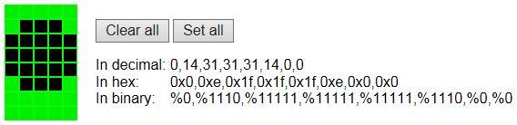
Hi at all, I found a thread on this Forum and because it is 5 years old, I decided to start a new one. The OLD Thread. I want to create some Pixel art on my nerdkit Display. I have read some Blogs and explanations about using the HD44780 for that. So I started to create some code. But the Display stays empty, no reaction to my code. Does anybody have some idea, why my code isn't working? This code shall Display the following:
From THIS Website. Maybe you have some suggestions. greetings lnino |
|---|---|
|
May 11, 2015 by BobaMosfet 
|
Inino- You need to set back to DDRAM using lcd_set_type_data() before calling lcd_home(), and you also need to actually output the character somewhere on the screen. Write now, you're just stuffing data into a small memory space in the display (CGRAM), but you're not displaying the character. If you look on page 17 of the datasheet for the HD44780 standard, normally the first 8 bytes (low) and first 8 bytes (high) in CGRAM can be customized. So, once you enter one, try outputting it as 0x00 (since it's in the first location in CGRAM. BM |
|
May 11, 2015 by BobaMosfet
|
Right now* |
|
May 12, 2015 by lnino
|
Hi BobaMosfet, thanks for your reply. Oh, I forgot to Show the saved stuff in CGRAM on lcd Screen. :-) Really sloppy mistake from my side. I have no microcontroller at the Moment to test the code. Shall this work like posted above? And why do I have to set lcd_set_type_data() before calling lcd_home() ? Some lines above I already Changed into data mode with the command lcd_set_type_data(). Isn't this still active and valid for every command which follows? |
|
May 12, 2015 by BobaMosfet
|
Inino- I'm sorry, I cut and pasted the wrong function name. Yes, you're already in data mode. What I meant to say was that you need to use lcd_set_type_command() to set BACK to COMMAND mode, before issuing the command to home the display. I can't speak for your simulator. I just know how it works for the HD44780 displays we use. It's possible your simulator doesn't support the feature, but I can't say for sure. That's something you'd have to determine. One of the things we use this feature for, is for a battery level indicator. We put 6 characters into CGRAM, each showing a step between full and no battery and then display accordingly based on battery charge. BM |
|
May 12, 2015 by BobaMosfet
|
Inino, One other thing-- you also need to set back to DDRAM (you switched to CGRAM, and left it there). Following your switch back to COMMAND mode, BEFORE your LCD home call, write this byte out, to switch from CGRAM to DDRAM. Overall process: Then you can clear, position cursor, write data, etc. BM |
|
May 12, 2015 by lnino
|
Hi BM, thanks for your reply. Oh, that makes sense to Switch back to DDRAM. I think this code shall work now. Hopefully I understood everything right. |
|
May 12, 2015 by lnino
|
I have tried my new code above, but I have still an empty screen. The screen itself and the wiring is okay, because I can display "normal" strings on it. Hmm, what can be missing? |
|
May 12, 2015 by BobaMosfet
|
Inino- Do you know if the emulator even supports this feature (it may not). Not all HD44780 displays (even real ones support this-- it's at the OEM's whim. The above is actual working code from one of our larger projects. You will note the use of macros and defines to make it more legible. Your code will look different. The above stuffs 6 characters into the CGRAM space, and the code works. |
|
May 12, 2015 by lnino
|
Maybe there is a misunderstanding. I am using no Emulator I am using a "normal" Nerdkit.
A Little bid enhanced and printed on a custom PCB. But the lib, the MCU and wiring are completely the same like on breadboard suggested by Nerdkit Manual. I have some other HD44780 Displays as well. I will have a look if I can find them. Maybe you are right that the Display does not have this Feature. I will give it a try. |
|
May 12, 2015 by JKITSON 
|
Inino.. Very nice setup... Jim |
|
May 12, 2015 by BobaMosfet
|
Inino- I would think it should work with the NerdKit 4x16 display, although I haven't done it with that one (those are in a parts drawer somewhere). BM |
|
May 12, 2015 by lnino
|
Hi BM, would be great if you can test my code on your Nerdkit. I am really interested if it works on your side. In the meantime I am wiring my other Displays to cross check. |
|
May 12, 2015 by lnino
|
@ JKITSON: Thanks. It was a really nice time drawing this PCB. On some places time for improvement, but as a fast development PCB it's quite time saving and still a Nerdkit. @BM: I have tried now another HD44780 single line. And here is the same result. The Display stays dark. Hmm, strange behaviour. |
|
May 12, 2015 by BobaMosfet
|
Inino- Then it's likely something with your code. In my code above PA2 = Port A, Pin 2-- which is connected to the RS line on the display. PA4 is Port A, Pin 4, which was the start of the 4-bit interface to 11-14 on the display. The main things are (not in order): If these are done correctly, you should be able to write any of the characters you've entered by referencing the ASCII value of 0x00 through 0x0F. In your case, just 0x00. But you might try 0x01 for grins. I no longer have a NerdKit set up to work with, and don't use their code, so I'm not really able to test your code right now. Welcome to the wonderful world of debugging :P BM |
|
May 13, 2015 by BobaMosfet
|
Inino-- If you haven't already, I'd walk through the nerdkits display code. You can't assume that it isn't the problem just because it works in basic use. In debugging, you have to look at the whole system and make sure each part of the system is doing exactly what you want. Their code might not conflict with what you're trying to do-- but until you verify that, you won't know. BM |
|
May 18, 2015 by lnino
|
Hi BM, I will try in the following days wiring the same Display with RS to a MCU pin. In combination with the fleury lcd library and some sample code. At the Moment the nerdkit lib is based on the fact that the RS pin is tied to GND. Maybe this has some affect to custom characters. Just an idea, but worth a try. |
|
May 18, 2015 by BobaMosfet
|
Ininio- I think you've found your problem. Holding RS to ground keeps the LCD in 'command' mode. In order to program the LCD, you have to hold that pin high in order to write data into CGRAM. BM |
|
May 18, 2015 by lnino
|
Hi BM, i was mistaken. With the nerdkit R/W is bound to GND. So RS is okay and is connected to the MCU. And sending commands to the Display must also work because the nerdkit lib uses the clear Screen, home and other functions via RS. Any other suggestions? This can be only something really simple and small. But I have no clue. I am trying to get the fleury lib working, this will take some time. Maybe somebody has some tipps for me in the meantime. |
|
May 18, 2015 by BobaMosfet
|
Inino, Understood. Since command mode has RS grounded, it might still be worth it for you to put an LED in parallel with the RS line, so you can see if the the LED blinks or has activity-- In data mode, it takes at least 1/10th second for each character to be written, so you should see the LED go high, which would mean the RS line is working. If you don't see this, then the code might not be addressing that line. I will look and see if I can find my NK code. If I find the nerdkit, I'll test my routine on it, and if it works, then we know that display supports it. BM |
|
May 27, 2015 by lnino
|
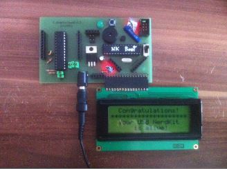
Hi BM, in the meantime I got my ordered Arduino UNO and I did some tests with custom characters on that. Took me 5 minutes to get custom characters working. The Arduino LCD Lib is really powerful. Do you were able to test my code on your nerdkit? I think we are not far away from getting this working on the nerdkit with the nerdkit lcd lib. Thanks a lot for your help. Attached you can see my arduino code and Setup:
|
|
May 28, 2015 by BobaMosfet
|
Inino- I haven't found my original 16x4 NerdKit LCD displays yet, or the NK sourcecode. However, the fact that you got it to work with Arduino at all, answers the question that the display can do it. Meanwhile, keep digging. It's probably something being overlooked. BM |
|
May 28, 2015 by lnino
|
Hi BM, you only need a HD44780 Display, ATMega168 or 328P. The nerdkit Lib and Bootloader you will find in the Download section of the nerdkits Website. Or do you mean you are looking for an older Code you have written on the nerdkit regarding the HD44780 Display? greetings Nino |
|
May 28, 2015 by BobaMosfet
|
Inino- I have 16x2 displays. I already know they work with the code I've shown-- have them in devices in stores all across the country. I don't use any NK code, I've written all custom code for performance and capability reasons. I have to put a breadboard together, put a project together for the NK code, and give it a try, then test your code, which I'm happy to do-- but I can't promise when. Just OBE right now. BM |
|
May 28, 2015 by lnino
|
Hi BM, can you give me your LCD lib and the constants? Because your code is not complete to get it working. Without the referenced library it's hard for me. used functions: LCD_MODE_COMMAND -- LCD_MODE_DATA -- write_byte used constants: LCD_DDRAM -- LCD_CGRAM I have done another try to get it similar to the arduino code, but the Display still Shows nothing. I used paper and pen to check if the numbers are correct which I enter. Shifting, AND, OR, but the numbers I am using are correct. 0x40 for writing to the first Position of CGRAM. 0x00 for calling afterwards. 0x58 for writing to the fourth Position of CGRAM. 0x03 for calling afterwards. Thanks a lot for your help. If you can test it sometime it would be very very awesome. But don't hurry there is no time Limit. So take your time. Maybe we can solve in the meantime writing. :-) |
|
May 28, 2015 by BobaMosfet
|
Inino- I can't provide the whole interface library we wrote, it's proprietary. The piece of shown you however provides a complete roadmap to writing to CGRAM if you understand the other information you have. I'll explain the parts that confuse you-- The macros I have in my code (LCD_MODE_COMMAND, and LCD_MODE_DATA) are nothing more than toggling the RS pin (happens to be PA2 = Port A, Pin #2) either 0 or 1, based on what RS has to be to tell the LCD what mode to be in. The label 'PA2' is compiler defined by the ATMEGA interface libraries, and I use PA2 because that is the pin I have connected to RS on the display. Your display is already initialized (nerdkit code) to auto increment (othewise you'd have to set the cursor position for every character you output), so you don't specify what CGRAM address to write into every time. You tell it what address you're starting at (0x00) and let it do the rest of the work-- that's why my loop simply writes all the data bytes for 6 custom characters all at once. Writing to the 4th position of CGRAM would not be 0x58. 4th position would be 0x43. I know this is confusing to you, but you have to look at the datasheet and understand how they specify the address bit pattern. So instead, set to 0x40 (which isn't just setting an address, it's telling it what memory space (CGRAM or DDRAM) that address is in as well), and then simply write byte data starting at 0x00 and let it increment position on its own. BM |
|
May 29, 2015 by lnino
|
Hi BM, thanks for your Explanation. But now I am completely confused. :-) I have found a Website where HD44780 custom characters are good explained. And the Content seams to make sense. Link When I use paper/pen and do calculate/shift with the arduino code, the 0x58 make sense to me. This is part of the arduino lib: And this is code for calling the function of the arduino lib: When I now enter the values into the code it Looks like that: Location = 0x03 AND 0x07 = 0x03 command (0x40 | (0x03 << 3) (0x03 << 3) = 0x18 because b00000011 << 3 is b00011000 (0x40 | 0x18 ) = 0x58 So the forth position of CGRAM is written when sending 0x58. And loading the forth position with 0x03. It Looks like the same like on the Website I posted above. Can you explain this to me? Because now I am very confused. |
|
May 29, 2015 by BobaMosfet
|
Inino- I apologize, 0x58 IS the start of character-position 4 (you are correct)-- I was thinking character-index, not row index. The reason they are masking with 0x7 is to drop any non addressable bits, and the reason they are shifting left 3 is because every 8 rows makes a character. However, as I stated previously, they should auto-increment every time you write a byte to CG RAM, so you only need to start at 0x40 and then write all your rows consecutively. You can check this (or set it yourself). See table 4, the list of commands in the link you sent. Look at #5 'Entry Mode'. You want to enter that command during initialization, and it will automatically make it index to the next memory location following each write byte. I'll bet it's being done in the intialization already. BM |
|
May 29, 2015 by lnino
|
Hi BM, I was talking minutes ago with another guy and now he founds the mistake. Such a tiny error, but with a big effect. I forgot to change to data mode before calling the saved custom character with 0x00. Here is the working code: And here you can see the result on the Display:
This was really a nice conversation with you BM and I learned a lot during this Project. Thanks for your help. And to all other Nerdkits Users, have fun now with a working code which you can use in your Projects. |
|
May 29, 2015 by BobaMosfet
|
Inino-- Fantastic. Yes, you have to set back to DATA. I actually have 4 routines-- write_nybble(), write_byte(), write_char(), and write_line(). write_nybble() and write_byte() do NOT set to DATA, because they can be used for either DATA or COMMAND. However, my functions write_char() and write_line() DO set it. As such I use write_char() for displaying the low-level battery symbol. Sorry I missed that. Just glad I could help. BM |
|
May 29, 2015 by lnino
|
I am now trying to make the code more readable and comfortable. I tried to translate one function from the arduino lib to the nerdkit lib. But I am only seeing a filled field on the Display. What I am doing wrong now? This is my new function in the nerdkit lib: And this is the Program of the main code: |
|
May 29, 2015 by lnino
|
Hi BM, now I got the lib working. I changed the Array to char Array, but I am quite sure this didn't Change a Thing. But then I changed the way of fillig the Array. First this way: (Won't work) This is the corrected Version: (Works) Any ideas why this works like that? |
|
May 29, 2015 by BobaMosfet
|
Inino-- The problems you're having are because you're still a novice at writing C. :) This declaration is wrong: The compiler doesn't properly evaluate a declaration and assignment in this case, because it got confused, because of the '8'. The proper way to write this is: The compiler can figure out how much memory is needed to hold it because you've defined all the data elements. For my part, since we're talking about a mini bitmap, I always use unsigned char or uint8_t. BM |
|
May 29, 2015 by BobaMosfet
|
Inino- One more thing-- make sure you only include a file once-- I see a duplicate include, in your code. BM |
|
May 31, 2015 by lnino
|
Hi BM, i have tried already before all possibilities I have known, but nothing worked. Also... did not work. It Shows also a completely full field instead of my custom character. Or do you mean, I shall Change the from char to uint8_t or unsigned char? Which duplicate do you mean? Maybe the delay lib? As far as I know the nerdkit delay lib Needs the gcc delay lib. |
|
May 31, 2015 by JKITSON
|
Inino Check lines 7 & 9 of your "include" Jim |
|
May 31, 2015 by lnino
|
Hi BM, I have another issue. I want to Show on my display Customer Characters from CGRAM and letters from DDRAM. But it seams thats the row I Transfer to the Display is not working. Everytime everything writes into the first line, also when I am telling that I want to write in the second line. I want to have in the first line on Position 4 the dot and in second line also on Position 4 the word "NERDKIT". But instead the text "NERDKIT" overwrites the dot. Here is the code: And the LCD of the code above Looks like that:
When I uncomment the String "NERDKIT", the code Looks like that: And the LCD Looks like that:
|
|
May 31, 2015 by lnino
|
Here is some additional test and a part of the nerdkit lcd for a better understanding: This code works and the result is good: Picture for the code above:
But this code has another result. But it should be the same, If I understood it right. It's just a function which is called. The Content is the same. Here is the Picture of the code above:
Here is the part of the nerdkit LCD Lib: I have really no idea why it overrides the Display with the last Input when using the lcd_goto_position command. Maybe you have an idea. :-) |
|
June 01, 2015 by lnino
|
Hi at all, I found the error regarding the Display Problem. The Forum search told me to Change from '-Os' to '-O0' in the makefile of the Project and the nerdkitlib Folder. The reason for that was that I installed some weeks before a new AVR toolchain and a new WinAVR. |
|
June 04, 2015 by BobaMosfet
|
Inino- Glad you found it. I don't remember off the top of my head if that's an optimizer flag, but if it is-- always be wary of optimizers. Additionally, I wanted to correct a statement I made to you- The above (the 8) is actually valid as well as the solution I provided. I apologize for the misinformation. I spend a lot of time writing in so many languages, each with their own peculiarities (and compiler or interpreter oddities), that sometimes knowledge jumps the fence into another area. BM |
|
June 04, 2015 by lnino
|
Hi BM, no Problem. Thanks a lot for your help and your patience. I also have to post an additional solution for my Array Problem. I had change my makefile and add the data section. Without that the Array is not able to get right initialized. After I corrected this, follwing declarations are working: Yeah, now everything works, like suggested. |
Please log in to post a reply.
|
Did you know that 20 LEDs can be controlled from 11 microcontroller pins, to make a twinkling heart outline? Learn more...
|


Copyright © 2013 by NerdKits, L.L.C.