NEW: Learning electronics? Ask your questions on the new Electronics Questions & Answers site hosted by CircuitLab.
Basic Electronics » Affordable oscilloscopes
|
November 02, 2009 by wayward 
|
I've been looking around the 'Net for a cheap oscilloscope that'll provide some basic functionality, as I am sure many of us NerdKittens have. I found something that looks interesting, but I can't really tell from its specs where the limits of its usability fall, so I am posting here to (a) ask someone experienced to check the specs real quick and respond if it's worth the money and trouble; and (b) give a heads-up to fellow beginners. Features Sells as pre-assembled: $49; DIY with SMD components already in place: $36; pure DIY: $33. There's also a "nano" version with color LCD, rechargeable batteries, SD slot and USB connectivity for $89. Would one of these two be a good starting investment? Thanks! |
|---|---|
|
November 02, 2009 by rajabalu21 
|
wayward, This is a great find. Thanks for sharing it with us. Thanks -Raja |
|
November 02, 2009 by mrobbins (NerdKits Staff) 
|
Hi wayward, I haven't looked specifically at those items, but be aware that "analog bandwidth" is a pretty important parameter to think about, and your post said 1MHz. That means that if you were trying to measure a 1MHz square wave in your circuit somewhere, it would appear on the scope as a gently rising and falling signal with about ~2/3rds of its "real" amplitude, instead of a sharp square wave. Considering you're working with a microcontroller at a clock speed of 14MHz+, this is really going to limit what you can do, and in fact if you have X MHz analog bandwidth, you can use it in practice for signals that are maybe an order of magnitude slower (X/10, so 100kHz or so). I did mention in another thread that the scope you've been seeing in all of our NerdKits videos cost $220 including shipping, and has 250MHz bandwidth, 8192 point memory, 2 channels, color screen. Ours may have cost 4.5x as much as the $50 one you linked to, but it also has 250x the bandwidth, 32x the sample memory depth, 2x the channels, etc. To summarize: if you're looking at signals slower than 100kHz, it's probably OK. But I expect you might very quickly outgrow the capabilities of this little one given the specs you've posted above, so just want to give you a heads up that alternatives exist that will give you a lot more room to grow if you are willing to look particularly for used units on eBay / etc. Mike |
|
November 02, 2009 by rajabalu21
|
Hi Mike, Could you please explain the difference between Logic Analyzer and Oscilloscopes? Since us kittens are involved in digital electronics will a logic analyzer be more useful compared to a oscilloscope? Thanks -Raja |
|
November 02, 2009 by wayward
|
Mike, thank you very much for your prompt response, and also for stopping me from causing damage to other people by inciting them to buy this before considering thoroughly. I missed your previous post about the scope you use; I'd definitely go the eBay route if I wasn't afraid of having to calibrate the beast, plus in my case mobility counts a lot (I don't live in the States so taking anything large out of the country with me could pose a problem). At the very least, now I understand better what I should be looking for in a scope and why. I thought that sampling at 2× the frequency in question will roughly suffice (I saw that somewhere in relation to PCM) but I see that an order of magnitude sounds much saner and safer. Thanks! |
|
November 04, 2009 by mrobbins (NerdKits Staff)
|
Hi Raja, A logic analyzer will only read 1s and 0s, so if you're strictly doing digital stuff, that could be fine. I just tend to deal with mixed-signal systems (where the analog meets the digital), or debugging issues with digital systems (perhaps where they aren't behaving digitally as they should), and that leads me to use an oscilloscope. NerdKits does not own a logic analyzer (yet) -- we're able to do what we need to do with the scope, debugging printf statements, LEDs, etc. In fact, you might be able to build a fairly capable logic analyzer with the NerdKit itself! I'll have to think about that one... Wayward, As far as the "sampling at 2x the signal frequency" rule, you should know that it refers to frequency in the Fourier transform sense, and specifically for pure sine waves. In fact, a square wave at 1 kHz has (sine-wave) frequency components at 1kHz, 3kHz, 5kHz, 7kHz... to infinity. (See this page about Fourier series of square waves for more info.) Now we can't really get a scope that has infinite bandwidth, so we have to cut those components off somewhere, and as a result you end up getting non-ideal square waves in your scope, where it takes some non-zero time to transition, might have some ringing, etc. But the farther you separate the frequency of the square wave from the bandwidth of the oscilloscope, the more frequency components you can measure/represent, which is why the 10x is really just a rule of thumb too! To be honest, we're really mixing up two issues: one is the analog bandwidth of the system (the 1MHz above), and the second is the ADC sampling frequency (5Msps, million samples per second). Both alter how your true voltage signal is captured on the scope, and both are related numerically (by design), but they're independent effects. Purely analog oscilloscopes, like many you'll find on eBay, have no sampling frequency at all, but still have an analog bandwidth. I'm an analog guy so I'm talking primarily about the bandwidth, but the "sample at 2x" rule you mentioned has to do with the discrete time sampling part of it (see Nyquist Frequency). Mike |
|
November 04, 2009 by wayward
|
mrobbins, that's pure gold. Thank you! |
|
November 04, 2009 by rajabalu21
|
Hi Mike, Thanks for the answers. Much Appreciated. Regards, -Raja |
|
November 06, 2009 by mongo 
|
I just took a look at the product line. I like the nano scope, for what it does and will likely get one soon. Thanx for the post... Evan though it's going to cost me more money. |
|
November 07, 2009 by rusirius |
I'll throw my two cents in here for what it's worth... (not much) The first thing to consider is rather you want a digital or analog scope... Most people thing "ohh, digital must be better" and that's not the case... For a long time I had both a digital and analog scope that I kept on the bench... Why? Because they each had their use... Digital scopes are great (especially a storage scope) when you are looking to analyze specific digital signals... For example, take a look at the nerdkit video about interfacing with a keyboard... With a good digital storage scope, you can hook the keyboard up, set it, hit a key, and see exactly what the signal it sends looks like... Compare a few keys and suddenly you'll have the full picture of what the thing is doing... Truth be told, since you're working with an MCU, MOST of the time a digital storage scope is going to be your best friend... When you're looking at DSOs, you have two main numbers to look at.. The samples per second it can take, and the storage or number of samples it can store. If it's too slow, you might "miss" entire sections of rising/falling edges of your waveform... If it doesn't store enough, you won't be able to catch enough of the waveform from the time it's triggered... Why do analog scopes still come in handy? Because what most DSO's gain in digital use, the lose in analog bandwidth... That means if you're having some sort of problem and looking for a "quick" glitch or something like that, you might miss it entirely with a digital scope since it "samples" the waveform periodically... An analog scope "deflects" from the waveform directly, so you'll catch everything (Within it's bandwidth) For example, I don't remember what, but I was working on something a couple years ago that was giving me serious problems and I just couldn't figure it out.. When I finally hooked up the analog scope, I found the source of my problem... I VERY fast sharp peak (a couple ns) that was slamming to about 30x my working voltage... The DSO I was using at the time missed it completely... There ARE however good scopes that will more than cover both areas just fine. I currently use a Tek 2440 which has WAY more analog bandwidth than I need and still has plenty of storage and works great for just about anything... One last note... In my personal opinion (and lots of others) you don't get much better than Tektronix when you're talking scopes... I'd highly recommend them... If you plan on buying new, plan on chopping both legs and maybe an arm off, but you can find great deals on the bay all the time... Just don't be in a rush, keep looking and checking and eventually a great one will come along... The 2440 I'm using now I purchased for less than I could buy a REALLY crappy REALLY slow REALLY useless brand new "china" scope for... It just takes time... |
|
November 28, 2009 by mcai8sh4 
|
Hi guys - I've found a Tektronix 2445 4 Channel analog oscilloscope for £150. So the obvious question is : is this worth getting, or am I better waiting for a storage/faster/cheaper/$YOUR_SUGGESTION_HERE/ ? I think there may only be a small window of opportunity for this so a prompt response would be appreciated. But if I miss out, then so be it :) Thanks -Steve |
|
November 29, 2009 by mongo
|
Several good points made since I last looked... I have used several O-scopes through the years from HeathKit to Tektronix. Every one of which was different from the last. At Bell Labs, we had these little rack units that plugged into a common carrier rack, You could put 4 different modules, like DVM, Freq counter, vector scope, etc. in it for four different purposes or have four complete little scopes. This was more than 30 years ago and it still impresses me with the compactness of the setup. I rebuilt an old RF analyzer to a crude scope and it sits here collecting dust these days because it is so big. What I am saying is: the small compact footprint is the key selling point for me. The sampling rates and resolution are secondary and there is always a way around these issues. Still planning on spending the $$ when it becomes prudent. |
|
December 03, 2009 by soundman003 |
I just bought on of the HP 54111D scopes and it didn't come with probes. I was wondering which ones would be the best to buy for it. Thank you |
|
December 03, 2009 by mrobbins (NerdKits Staff)
|
Hi soundman003, We just got a pair of these generic 100MHz 1X/10X probes. Remember to adjust the probe capacitance for the scope -- and remember to re-adjust when you switch between 1X and 10X modes! Mike |
|
December 03, 2009 by soundman003 |
Mike Thank you for your reply. I am not sure how to adjust the probe capacitance. I am still learning. Maybe you can do a tutorial on scopes and show how to connect to and read some things. :) Thank you again |
|
December 08, 2009 by BobaMosfet 
|
soundman003 (and others)--- Here are some very important things to bare in mind when looking for an oscilloscope.
If you can buy tektronix- do it. There is a reason they are the standard.
A. Make sure you are selecting the right probe for the job, to begin with. B. Make sure you understand what you are doing with adjusting probe capacitance (this has to do with induction and capacitance and "ringing" which you can learn about). C. Determine, before you adjust the probe, whether or not you really have to. Electronics do not require (for the majority of it) a nice crisp square wave, all nice and neat at the leading and trailing edges. What it does require, is that the leading and/or trailing edge of a wave be sufficiently different from any other part of the waveform (whether that is ringing or anything else in the waveform) that the signal can reliably and regularly be triggered on. depending on which edge is being watched for. Some things to try with your new scope:
*NOTE: The length of the ground-wire on your probe directly affects the quality of the signal the prob reads. A ground-wire too long will affect capacitance of the probe. The shorter the better. Bear in mind however, that unless you are looking for the most delicate deviation, or can't tolerate ringing in the signal-- strap length won't effect you much. Hope that helps, enjoy, be careful, and good luck! |
|
December 09, 2009 by mcai8sh4
|
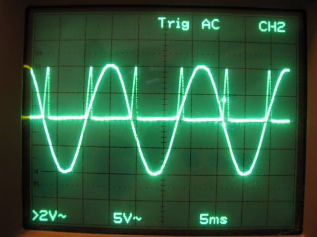
I just received a scope today, sadly not a techtronics one - I got a cheap Hameg one - if it comes in useful, then I'll get a 'good' one at a later date. BobaM, your post was perfectly timed for me, and most useful. I have measured my crystal (well, I got a wave!) and then with a simple program to turn an LED on and off at 5ms intervals, saw that it is actually changing every 5ms. So I'm happy. I haven't calculated the freq of the crystal yet, but I'll see how accurate I can get it to (it doesn't have an frequency counting 'thing' - as far as I know). |
|
December 10, 2009 by BobaMosfet
|
mcai8sh4-- Excellent, glad I could help. Any o-scope is better than no o-scope at this level-- particularly when dealing with frequencies. Take a look at both legs of your crystal-- the sine wave might be a tad different on one leg versus the other-- (skewed or "pushed" slightly). This is usually the way the waveform looks after it's come out of the MCU-- and is called 'frequency response'. Also, bear in mind that if you do see a very slight noise on the wave-form (like the calibration wave or other square wave), this can be anything from 60Hz (AC outlet frequency is everywhere, to noise from resistors (called 'Johnson Noise'). Again, don't sweat little noise, unless it interferes with a component's ability to reliable trigger. Your scope should have something that atleast tells you the frequency of the wave. If not, you'll have to calculate it based on the timescale and reticule. |
|
December 11, 2009 by Rick_S 
|
I agree completely with you BobaMosfet when you said Any o-scope is better than no o-scope at this level. I was given an old Tektronix 2211 scope. And while it may not be the latest and greatest and is only a 50Mhz scope, it has proven very useful. For example, a few months back I was trying to develop a circuit to dim incandescent lights with a triac controlled by the micro-controller. I knew I had to have the triac off at the zero cross of the AC and turn it on at varying times after that. Without the scope, I would have probably not figured out why my program wasn't working. The scope allowed me to view the AC wave form from my house as well as the pulses I was generating with my zero cross circuit.
I could also see the output to the triac (though I don't have a photo of that :D ) So I have to agree completly. Before I got this scope, I didn't think I'd really get much use from one. Now I find myself turning it on quite regularly. BTW, Boba, thanks for the GREAT instruction in this thread. I have had no formal scope training and that information is VERY useful. Rick |
|
December 12, 2009 by soundman003 |
Thank you BobaMosfet for the reply. I bought one of the HP-541111D scopes used and I know what you mean about the probe cost. Also thank you for the tutorial I have allot more learning to do I wish I could find a good book on Digital scopes that would show how to use them. |
|
December 12, 2009 by georgio 
|
Hey soundman003, I have an O-scope PDF file i can send you. It has oodles of valuable information. If your interested, and this goes for anyone else that would like it, shoot me an e-mail. jrodriguez404@gmail.com George |
|
December 12, 2009 by Rick_S
|
George, I'd love a copy too. E-mail on it's way. Rick |
|
December 12, 2009 by soundman003 |
George I would like to get that. Thank you |
|
December 13, 2009 by soundman003 |
Hello I was wondering if somebody might be able to tell me how to set up my scope to see the signal from a DMX transmitter? I have the HP-54111D scope. Thank you |
|
December 13, 2009 by BobaMosfet
|
DMX operates in the ISM unlicensed frequency band. The device you have will either transmit many channels on one frequency, or it will hop frequencies. Depending on frequency, you won't even be able to trigger on it, unless you have a scope that operates in the 4-12 GHz range, and if the frequency hops, you will have a hard time following it. The first question you need to ask is what frequency is my device transmitting at? 900MHz or 2.4GHz....? Or What? If it's too fast, your scope won't even see the slope. Remember, an oscilloscope can do only one thing-- graph changes in voltage over a period of time. That's all. |
|
December 14, 2009 by soundman003 |
BobaMosfet Hello and thank you again for the response. The transmitter I am using for DMX is hardwired and it uses a cable between the transmitter and receiver.The clock for the Atmel is at 8mhz also the BUAD rate is 250k. I thought my scope would see it but I must be doing something wrong. It does see a signal but I cant seem to break it down to the bits. I was hoping I could look at it like the keyboard interface tutorial here. |
|
December 15, 2009 by BobaMosfet
|
Your DMX transmitter is transmitting at either hundreds of millions to several billions of cycles per second. Well above what your ATmel chip can even realize. Nor will your oscilloscope unless it is approximately 5 times faster than your DMX signal. Whatever you are monitoring a signal with must be faster (approximately 5 times or so) than the signal itself. |
|
December 15, 2009 by mrobbins (NerdKits Staff)
|
Hi soundman003 and BobaMosfet, I think there is some confusion about what protocol is trying to be analyzed. I think that soundman003 is referring to DMX512, specifically the wired ("baseband") asynchronous serial protocol at 250kbaud. I think that BobaMosfet is referring to "wireless DMX", which may or may not be a vendor-specific kind of thing -- I'm having trouble finding details. I think some of the confusion came from the word "transmitter", but I don't think that was intended to mean RF / wireless. Just wanted to jump in and get everyone on the same page :-) Mike |
|
December 15, 2009 by soundman003 |
Mike Hello and thank you for your reply also. Sorry about the confusion, it is the wired serial protocol. I was hoping to get a look at the signal kinda like you did on the PC Keyboard interface tutorial which I was wondering how you hooked that up. I am trying to learn how to use the trigger better on the scope. Also thank you BobaMosfet for your reply and help. |
|
December 19, 2009 by BobaMosfet
|
Mike, Thank you for that- heh heh heh.... that helped A LOT. Soundman-- I don't know what scope you've got, so I'm going to give you the broad strokes--
Study your 'TRIGGER' options- that will help learn what you can 'trigger' on. Hope this helps, BM |
|
December 20, 2009 by soundman003 |
BobaMosfet Thank you again for the reply. I am using the HP-541111 DSO. I will give the examples a try. I am tring to learn how to use it and am getting there. Thanks for the help |
|
December 20, 2009 by BobaMosfet
|
soundman003-- A couple of things to consider-- Sometimes, all that is sufficient is that you are watching the screen, cause something to happen and you can see that a voltage change did indeed occur-- in other words, waveform is not important, the fact that the voltage level changed is. You can also have other modes of acquisition-- for example, normally it will be in SAMPLING mode-- it picks up every jitter and displays it as a noisy line, not neat and smooth (Note that 60Hz is everywhere, so unless your scope can filter that you will NEVER see a smooth line in sampling mode). If you can set it to an AVERAGING mode, it takes a longer time to see a full (REPEATING!) waveform, but it will appear relatively smooth and may yield a more accurate result if your scope is also displaying information (like amplitude, frequency, voltage and peak to peak info, etc). Play with it. When in doubt, DONT connect it-- triple check everything until you are really comfortable with what you are doing (and even then double-check). Seriously, be careful and save your scope-- better to not use it then to burn it or a probe up. But play with it and learn... it isnt magic. If you arent seeing what you expect, make sure your expectation matches how the scope is configured. Perhaps your expection isnt achievable or proper-- so think about that too. We look forward to your examples! :P -BM |
|
December 20, 2009 by BobaMosfet
|
Sorry for the wide response-- I didn't realize it would do that (but now sees obvious)... |
|
December 20, 2009 by soundman003 |
Mike Thank you for the response. I will be playing around with the scope. I found a circuit on line that is suppose to let me see the DMX wave on my scope so I am going to build it and see what happens. I really appreciate you guys helping me out. I am also going to see if I can do what you did with the scope to see the data and bits on the PC Keyboard tutorial. |
|
December 21, 2009 by soundman003 |
BobaMosfet Thank you for your response :). I will be trying different things and see what happens. |
|
March 17, 2010 by mongo
|
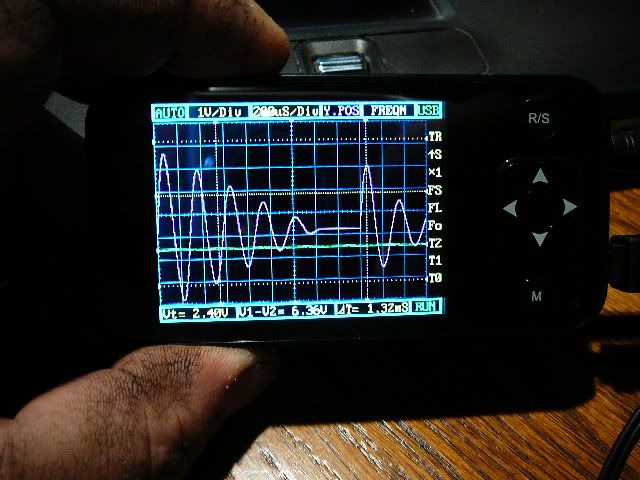
Well, it's here! I ordered it around Feb 12 and it finally showed up today, March 17. Shipped directly from Hong Kong. What is not included is a charger. It does charge from a USB port or if you have a Motorola RAZR phone, it should plug right in to that charger too. Also not included is a comprehensive instruction manual. There is a manual of sorts but not so easy to follow. You can tell it was translated to English. After playing with it for a little while, I find it is not so hard to use, it just takes a little thinking to get it set up for what you need to do. Also not included id the Micro SD memory. It takes a max of 2GB. I haven't had any luck with firmware upgrades or other software from the site listed in the little manual but will keep trying. There are some nice little features that are on the screen. Measurements can be made from various markers and the trigger level is not only selectable, but also shows it on the screen. Measurements include: Freq. cycle, duty, voltage DC and average AC / RMS voltage. Time bases range from 1uSec / div to a full 10Sec / div Input ranges from 10 mV / div to 10V / div (for those unfamiliar with the terms, div is one grid square) Bandwidth is 1MHz. Though it's not a high bandwidth scope, not much really needs it anyway, unless you are working on RF circuitry or fast processor speeds. It is based on a 32 bit ARM Cortex (R) -M3 compatible processor and A/D resolution is 12 bits. (never mind the stained digits... I work in the petrochemical industry and it gets into the skin) |
|
March 17, 2010 by mcai8sh4
|
Mongo, nice review. I have a friend who got one of these a couple of weeks ago. I've not yet been able to play with it though. I'll ask him about firmware upgrades etc, and if he has any info, I'll let you know. Through work, I occasionally delve into the petrochem industry, so I'm well aware of 'working' hands :) Take care, -Steve |
|
March 17, 2010 by Phrank916 |
mongo- I found this forum that might be of interest to you. http://bbs.e-design.com.cn/bbs/index.asp?boardid=5 It's in Chinese but I ran it through google translate and it's fairly readable. Looks to have a bunch of links to modified firmware for the device. Ted |
|
March 17, 2010 by mongo
|
Tried the link... I have trouble with the Chinese. It doesn't translate for me. |
|
March 18, 2010 by Rick_S
|
Paste the link in google, do a search, then select translate on the search result. That worked for me. How do you like it so far? I've tossed around the idea of one of these for a while (or the jyetech kit type) but so far haven't bit the bullet. I could see it being quite handy for quick checks. Does it work as you'd expect? Rick |
|
March 18, 2010 by Phrank916 |
Go here and paste the link into the "Translate a web page" section toward the bottom. |
|
March 18, 2010 by mongo
|
Well, I translated the link... Didn't really have anything I didn't already know however. I do appreciate the help guys, we shall see what happens. So far, the only thing I wish it had was an external trigger so it does not depend solely on the signal level for it. I can make it work anyway but it would be a nice feature. I also happened to have a USB cable with the right connector so it can run from the power provides as well as charge the battery. Overall, I am pretty happy with it. I added a micro SD card from one of my old phones and can now store and read back waveforms. That's something my old scope (dinosaur) never could do. In fact, it didn't have a trigger either... Two alligator clips came with it that I assume are to give a little variety on the probe connections but I have yet to figure out how they are supposed to connect to the little clips on the main leads. |
|
January 27, 2011 by BStory 
|
What do you guys think about this one for a cheap logic analyzer? It's open source stuff. http://www.seeedstudio.com/depot/preorder-open-workbench-logic-sniffer-p-612.html?cPath=75 I'm reading that it is 50Mhz at 32 channels and 100Mhz at 16 channels. |
Please log in to post a reply.
|
Did you know that signed numbers need to be sign-extended when chaging variable sizes? Learn more...
|


Copyright © 2013 by NerdKits, L.L.C.