NEW: Learning electronics? Ask your questions on the new Electronics Questions & Answers site hosted by CircuitLab.
Sensors, Actuators, and Robotics » Proximity Sensor Project
|
October 22, 2009 by timk |
Hi I am a new NerdKit trainee and would like some assistance with a project. I need some examples of how to interface the nerdkit with some industrial sensors. Allen-Bradley -Rockwell Automation Sensor Catalog Number 872C-DH3NN12-D4 Input: 10-30VDC Load: 200mA Output: N.O. NPN Shielded The Sensor has 3 connection
1 - "+" (Positive)
3 - "-" (Negative) What I would like to know how to do is this. I have 2 of the above sensors I will refer to them as SA and SB. All I want the circuit to do is turn on a relay if SA detects an object and SB Does not. In other words. Every time SA detects a metal object SA should also. It SA Detects and SB does not then turn on the relay. I realize I will have to power the sensors with a different power source but I am not sure how to design the circuit or software. Any help would be great Thanks P.S. This kit has been great so far. Thanks |
|---|---|
|
October 22, 2009 by n3ueaEMTP 
|
Timk, I too am like you, still in the trainee phase. Most of the projects I've build so far have been nothing more than adaptations of the original source code that came with my kit. That being said, I have ventured out of the cut and paste programming method to do something similar to what you need done. If I understand you correctly, you want a relay to activate ONLY when both sensors detect the metal object. Here is the code I use to reset a counter (which also resets the EEPROM counter to zero as well) In the case above, PC4 & PB5 are both resets for other things. When they are both pushed, they reset the counter & the counter stored in the EEPROM. When they are pressed indivudially, they only reset their respective items. In your case, you would want to change to where PC1 is set as an output. Keep in mind that their probably is a more efficient way to preform the same tasks but this is the one I have used with success. Hope this helps Chris |
|
October 22, 2009 by mrobbins (NerdKits Staff) 
|
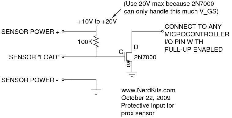
Hi timk, Let me try to help on the electrical side of this question. I found this datasheet which seems to include your part, and specifically it is the first row on page 2. This indicates "Output Configuration: N.O., NPN". The "N.O." means Normally Open, which indicates that when no object is present, it will be in an "open-circuit" mode, meaning that no current will be allowed to flow into the "load" terminal. The "NPN" refers to a type of transistor, and while it specifically refers to a bipolar junction transistor (BJT) -- see our Piezoelectric Sound Meter tutorial for more info about them -- it is very similar to the n-channel MOSFET we discuss in the first few pages of The NerdKits Guide. But it indicates that the vircual on-off switch is located between the load terminal and ground. (This is further reinforced by the wiring diagrams on page 4 of that datasheet.) So I've sketched up one way you might connect this sensor to your microcontroller. This solution addresses the different voltage requirements of the sensor and MCU, and simultaneously adds protection by putting an insulated gate between the sensor and the microcontroller (using a 2N7000 MOSFET which is included with your USB NerdKit).
The 100K resistor is a "pull-up resistor". When the sensor is "off" (no object detected), the MOSFET gate voltage is pulled high and the MOSFET turns on, which means it will pull the microcontroller pin voltage down to ground (it will read as 0). When the sensor is "on" (object is detected), the MOSFET gate voltage is pulled low, meaning the MOSFET turns off. This allows the microcontroller's pull-up resistor to pull the voltage high (so it will read as 1). You could build one of these for each of your two sensors. Welcome to the NerdKits community, and let me know if any of the above is unclear. Hope this helps get you started! Mike |
|
October 22, 2009 by rusirius |
You'll have to look up the exact specs to know for sure, but based on the info provided I'm guessing that you can essentially treat it the same as an NPN transistor with the "proximity" sensor being the base... In other words, you will hook the + and - up to the supply... The pin you refer to as the "Load" is generally going to have a + voltage in reference to ground... When something activates the proximity sensor (and therefore turns on the transistor) that pin should be pulled to ground. So + when nothing and - when something... HOWEVER... bear in mind that since this requires at least 10V DC, you'll need to isolate it from the MCU... The best way to do that is with an opto-isolator... (4N35/4N37 are the ones I most often use). (drive the opto-isolator with the sensor and then interface the output to the MCU) Also, if you're driving a relay, keep the application in mind and design appropriately... For example, let's say this is some sort of safety device... You may want to drive the relay ALWAYS when no metal, or both detect metal, but turn it off when one detects and not the other... (Use the opposite contacts on the relay (N.C. or N.O.) to keep that side working the way you want). This way if your "safety device" fails, instead of "not" triggering, it will trigger by default... (i.e. the device is KEEPING it in a working state, not being relied on to fail it...) Now one last note... Not having any idea what you're trying to accomplish here, are you sure you even need the MCU? Unless you've left out a lot of details you're basically describing an XOR gate... If neither sensor detects or both sensors detect then one thing happens, but if one detects but not the other, something else happens... If you used a simple XOR gate you'd be much cheaper and easier... (you'd need to add a small transistor to drive the relay, but that's it otherwise)... Heck, you could actually build it out discreetly with a few diodes and a transistor... |
|
October 23, 2009 by timk |
I have tried to attach an image of the purpose of the project. Not sure if it will work though. It is a tiff image and I am not sure what types will work. When I preview the post all I get is "Project Image" First Thanks to all that have responded. I have always wanted to do this kind of stuff but have been afraid to try. So far it has been fun, and I don't think I have blown anything up yet. "at least I haven't seen any smoke" Brief description. It is a prototype of a system that believe it or not, checks the length of nails. "Yes Nails" Put simply, The nails slide down vertically between 2 rails. The 2 sensors will be mounted on the face of one rail with A directly above B. If Sensor A detects the presence of a nail then B should also. If A does and B doesn't then energize a relay and display a "Short Nail Detected" message on the LCD. This whole idea may or may not even work. I am not even sure the sensor is fast enough. After all the nails will be passing by at about 1500 to 2000 per minute. |
|
October 23, 2009 by mrobbins (NerdKits Staff)
|
Hi timk, The image feature currently requires you to host your own image somewhere, whether in your own webspace or on some public photo-sharing site, and then giving the full URL to the photo. I haven't worked with this kind of inductive sensor before, and I suspect that you'll be able to get it working, but in any case it sounds like your project might also be able to use a light-based sensor -- an LED on one side, and a photodiode or phototransistor or photosensitive CdS cell on the other side. Best, Mike |
|
October 23, 2009 by rajabalu21 
|
Mike, Could you tell us what software you use for preparing the circuit diagram? Thanks -Raja |
|
October 23, 2009 by mrobbins (NerdKits Staff)
|
Hi Raja, I've been using xcircuit which on Debian Linux is just "apt-get install xcircuit" to install. Mike |
|
October 23, 2009 by rajabalu21
|
Thanks Mike. I need to figure out a way to get this to work on Windows Vista. Thanks -Raja |
|
October 25, 2009 by timk |
Ok I think this might work. This should give you an Idea of what I want to do.
Thanks TimK |
|
October 26, 2009 by timk |
Hi, I have thought of using optical sensors but I think the dirty environment(oil and dust) the machine is in would be a problem. Even the nails coming down the rail are covered in oil. Thanks Timk |
|
October 26, 2009 by mrobbins (NerdKits Staff)
|
Hi Timk, Thanks for the sketch. Have you had any progress in interfacing with the inductive sensors as discussed above? Best, Mike |
|
October 26, 2009 by timk |
Hi Mike, I am working on setting up a power supply. I have several wall transformers for different electronic devices. Just trying to find on with enough amps to run this and power the sensors and a relay. I will let you know not if, but when I have a problem. Thanks for your help. Timk |
Please log in to post a reply.
|
Did you know that interrupts can cause problems if you're not careful about timing and memory access? Learn more...
|


Copyright © 2013 by NerdKits, L.L.C.