Piezoelectric Sound Meter

NerdKits was recently a sponsor of MIT's Battle of the Bands 2009, a fundraising event which supports the Children's Miracle Network, and also is a popular gathering during MIT's Campus Preview Weekend for incoming students.
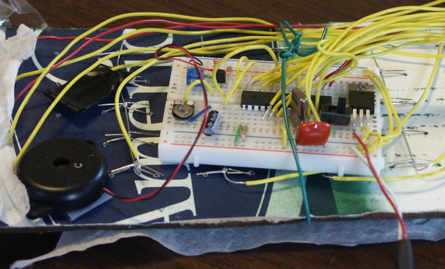
To show off our microcontroller kits during the event, we built a sound meter which uses the piezoelectric buzzer (included with our USB NerdKit microcontroller kit) in reverse, as a microphone. This provides an opportunity to demonstrate a single transistor amplifier, to make the signals from the piezoelectric element big enough for the microcontroller's analog-to-digital converter (ADC) to read.
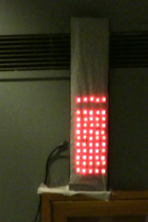
Since our sound level meter had to be visible in a big room (the Lobdell food court in MIT's Student Center), we opted to use our bright red LED Marquee, which has 120 high-intensity red LEDs all controlled by the one ATmega168 microcontroller. We won't talk about how we built that LED array on this page -- it has its own video tutorial and related materials which you should reference for that part of the project.
Here are a few photos of the finished product: (click to enlarge)
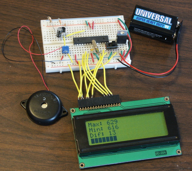
We also have a version that runs on the 20x4 character LCD screen that's included with our kits. That way, you can build this separately from the LED array. It also provides more debugging information, such as the minimum and maximum analog-to-digital samples that were measured during each period. Click the thumbnail below to enlarge:
Analog Amplifier Details
In the video tutorial, Humberto gives an extended description of the math behind how the amplifier works. This includes concepts such as a simple model for the NPN bipolar junction transistor (BJT), biasing, how to calculate gain, and adding more gain at higher frequenies with a technique called "bypassing".
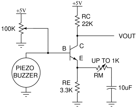
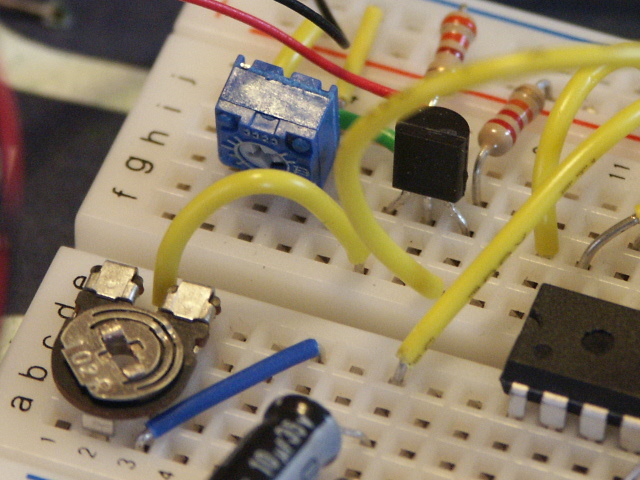
In the schematic above, the 100K potentiometer is adjusted until the transistor's collector current is approximately 100 microamps (10-4 amps). This is measured with a voltmeter across RE until the voltage is approximately 0.33 volts. Please watch the video for a full explanation of the transistor model and how we build up to this circuit.
Gain Calculation
Following along with the assumptions made in the video, and ignoring RM and the 10uF capacitor, the gain of the amplifier is approximately 22K/3.3K = 6.7. But at higher frequencies, the 10uF capacitor looks like a short, and the gain of the amplifier is roughly 22K / (3.3K // RM). This last part in the denominator (RA//RB) means the parallel combination of two resistances, which equals (RA*RB)/(RA + RB).
If the resistance loading the emitter is small, then we can't make the same assumption that we made in the video that a change in voltage at the base will necessarily be followed by an almost identical change in voltage at the emitter. Previously, the change in VBE was small enough compared to the change in voltage across RE. But if RE is small or zero, the change in VBE will become important and limit the gain of the amplifier. Here's how this comes out of the equations:
As noted in the video, the two governing equations for this simple model of the NPN bipolar junction transistor (in forward active operation) are:
The first of these says that the collector current is simply β times the base current, and the second says that there is a steep (exponential) relationship between VBE and base current. (If you're curious about numbers here, then for our 2N3904 transistor, β is typically 100-200, IS is typically around 10-14 amps, and Vth is about 25mV at room temperature.) Now we can also write, by definition, that the VBE is simply the difference in voltages at the base and emitter:
and then, for a resistance RE between the emitter and ground, we know that VE = RE * IE, and since IE is approximately equal to IC, VE = RE * IC. We plug this in, and move VE to the other side of the equation, to get:
This just means that the voltage from the base to ground is a combination of the base to emitter voltage and the voltage drop across the emitter resistor RE to ground. But this equation is interesting, because on the left side is VB which is our input voltage, and on the right side, everything is a function of IC, the collector current, which is related to our output voltage:
This is just Ohm's Law for the resistor RC -- an increase in current through it (and also through the collector) increases the voltage drop across it (which is why this is negative). We can rewrite this in a calculus way as a derivative:
And now that the above equation connects IC to VOUT, to complete the full gain chain and get from VB (the input) to VOUT, we really just need to connect from VB to IC, because:
Fortunately, we can actually calculate (dIC / dVB) from the equations we wrote a few steps ago. Starting with VB = RE*IC + VBE, we can take the derivative of both sides with respect to IC and find:
This last little part dVBE/dIC can be found right out of the two transistor equations we had earlier:
where the (1/Vth) comes from taking the derivative of the exponential. Now, we can notice that the second part of the last equation is actually IC itself, and we can simplify:
or taking one divided by both sides (inverting both fractions):
As we said before, Vth is about 25 millivolts at room temperature, and IC was picked to be 100 microamps, so in this case,
So now we can go back and substitute this in to figure out the amplifier gain:
So if RE is much greater than Vth / IC (250 ohms in this case), then we get back to our original simplified gain equation that was derived in the video, dVOUT / dVB = - RC / RE. But now if, for example, RE = 0, then while the earlier gain equation would have suggested infinite gain (dividing by zero), our new one would suggest that it's really - 22K / (RE + 250), or a (negative) gain of about 88 for RM = 0. With RM = 1K, as in our actual potentiometer in our circuit, the (negative) gain is about 18. Having a potentiometer or just swapping out resistors lets you change the gain over a wide range.
We hope we were able to present that in a useful way! Also, there's a lot of analog aspects to even a simple single-transistor amplifier like this that we didn't cover here:
but if you're interested in further study of analog circuits, there's a lot to learn. We highly recommend the following resources:
although note that the second one expects a lot of mathematical comfort. Also, if there's interest expressed from our NerdKits customers, we can certainly start making more analog-oriented video tutorials!
Parts List
Beyond our USB NerdKit, a few extra parts are required:
| Photo | Part | Quantity | Description |
|---|---|---|---|
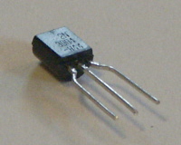 |
2N3904 NPN BJT | 1 | The 2N3904 is a commonly available NPN bipolar junction transistor, and certainly has the gain and frequency performanace for low-frequency applications like this one. (See manufacturer's datasheet.) Other NPN transistors, like a 2N2222, will also work fine in this application, but note that substituting a MOSFET may not produce the results you expect. MOSFETs don't have the same exponential current-voltage relationship that bipolar transistors do, so the math can be quite a bit different. |
 |
Resistors, one each of 1K, 3.3K, and 22K | 3 total | Several 1K resistors (brown-black-red) are included with our USB NerdKit, but the other two sizes, 3.3K (orange-orange-red) and 22K (red-red-orange) are needed as well. Also, instead of a 1K resistor, our configuration shows a 1K potentiometer, which lets us have a continuous gain adjustment, but this is optional and not needed. With just the 1K resistor, you can still demonstrate three gain settings: RM = infinite, RM = 1K, and RM = 0 (just a wire). |
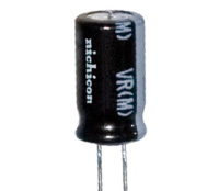 |
10uF capacitor | 1 | This 10uF electrolytic capacitor is needed to perform "bypassing" to get higher gain at high frequencies. Please note that this kind of capacitor is polarized, which means it can only tolerate a voltage across it in one direction. There is a lighter stripe down one side of the capacitor which is adjacent to one of the leads: this lead must connect to the lower voltage, which in this circuit is ground. |
For the LED array version as shown in the video, the LEDs and overall array setup from the LED Marquee project are also needed.
A multimeter is highly recommended for building and debugging this project. We have two different models available in our store.
Source Code
The code for this project is mostly a mix of the temperature sensor code that's developed in our NerdKits Guide (using the ADC to get a value from an analog device) and the LED Marquee. There really are no new concepts on the microcontroller programming side. Here is a list of the few slight modifications we made:
Since we do not expect everybody to try to make an LED Marquee, we also made a version of this code that works with just the LCD. This code measures volume the same way, and has the same amplifier described above, but instead it just prints the information to the LCD, and represents the volume bars using black characters on one row of the LCD.
For the LED array version, you can download the source code here. Start with a standard NerdKits microcontroller project and Makefile (included with the kit) and plug in this source code.
For the LCD version, you can download the source code here. Start with the standard NerdKits microcontroller project and Makefile (included with the kit) and plug in this source code.
More Videos and Projects!
Take a look at more videos and microcontroller projects!
Comments
|
Did you know that our USB NerdKit works on Windows, Linux, and Mac OS X? Learn more...
|


Copyright © 2013 by NerdKits, L.L.C.