NEW: Learning electronics? Ask your questions on the new Electronics Questions & Answers site hosted by CircuitLab.
Support Forum » traffic light project
|
June 03, 2013 by rolf |
Does anyone have the wiring instructions for this project? The photo included in the projects section is not enough (at least for me). |
|---|---|
|
June 03, 2013 by pcbolt 
|
Rolf - Inside the "trafficlight.c" source code file are the wiring instructions... |
|
June 03, 2013 by rolf |
Thanks pc. But I need more than this. See photo in Projects section of website. Rolf |
|
June 03, 2013 by pcbolt
|
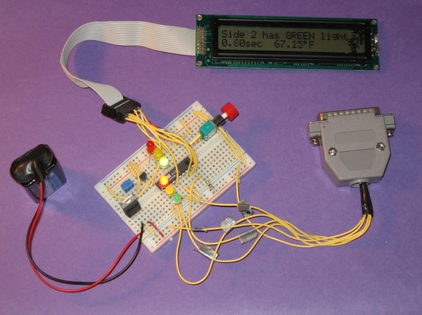
Is this the photo?
If so, it looks like it might be a little out of date. I don't think the wiring shown will work with the downloaded "trafficlight.c" code. |
|
June 03, 2013 by rolf |
That is the photo and I must admit that I think I've got it figured out and will sooner or later get around to giving it a try. The photo leaves out the oscillator. What else do you see that seems wrong? Also, please look at the code for traffic light. It includes a number of commands that are for tempsensor. Hard to believe that it will work even if it compiles and if it doesn't I'll have to figure out what to edit out. I bought this kit rather than an Arduino because of the many comments regarding how much one can learn from it. Didn't figure that I'd have to learn from their mistakes as well as my own (I am a rookie at all of this and at the age of 73 I don't have the patience that I once did.). Thanks again. Rolf |
|
June 03, 2013 by Noter 
|
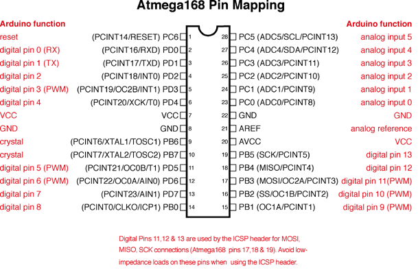
The idea is to build on the temp sensor lesson by adding traffic light functionality. The temp sensor is still functional in the traffic light program. So if you have the temp sensor working, just add on the leds and switch for the traffic light and give it a go. It's a good idea to get used to working from the datasheet and chip pinouts rather than relying on a photo anyway.
|
|
June 03, 2013 by pcbolt
|
It looks like the LCD is wired differently, the parallel port plug isn't needed, the push button is wired to PORTD in the photo (the code has it on PORTC), and the LED's are wired to PORTD and again the code has it in PORTC. I think the photo came from an MIT class project so it really isn't a mistake it just was built way before the USB plug and 4-line LCD was introduced to the kit. I actually built this project a year or so ago and didn't need to change the code at all. I'm pretty sure you could even leave out the tempsensor and it will still work. The whole premise of the NK is to keep challenging you to learn more by experimenting. I think once you get past the initial frustrations, you'll find yourself learning a great deal...of course patience would be a good asset to have :-) Good luck, Rolf. |
|
June 03, 2013 by rolf |
Noter: I should be able to take it from here. Maybe I can regain some of that lost patience. I am (with the help of members of the forum) learning, and that is the point of all of this. Once again, my thanks for your help. |
|
June 03, 2013 by rolf |
Hey guys. It works :-). Thanks once more for your help. Rolf |
Please log in to post a reply.
|
Did you know that you can build a giant scrolling LED array with our microcontroller kit? Learn more...
|


Copyright © 2013 by NerdKits, L.L.C.