NEW: Learning electronics? Ask your questions on the new Electronics Questions & Answers site hosted by CircuitLab.
Basic Electronics » Limiting battery discharge?
|
February 27, 2013 by Ralphxyz 
|
I have a 20 volt lithium battery that runs down to 17.6 volts and then stops. This is from my B&D weed whacker. I would like to use the battery on one of my circuits/components how would I limit the discharge? I am really leery with the lithium battery but figure B&D must feel it is safe. There appears to be three contacts I would assume one is for temperature. I know there is a temperature circuit as the battery will not charge if it it is over a certain temperature. Of course using the B&D charger takes 8 hours to charge, I would also like to figure out how to do a quick charge. Ralph |
|---|---|
|
February 27, 2013 by rajabalu21 
|
When you say limiting discharge, I am not sure whether you mean (1) You want the battery to stop powering the load when its voltage drops below a certain predefined voltage. If so please take a look at this. Or (2) If you are thinking of just limiting the current supplied to the external load. Then you could use a PTC/Poly fuse in series so as to stop supplying power all together in case of a short circuit. As for charging faster, I could not find the spec of the battery to ascertain how fast it could be charged. You can take a look at this site. They have many chargers that could help you select the charging rate. I am familiar with this specific model and it is very flexible. -Raja |
|
February 27, 2013 by Ralphxyz
|
Hi Raja, thanks. #1 was what I was looking for. I found a new B&D charger which "claims" 40 minutes so that is a big help. Boeing is having problems with lithium cells discharging to much, so I want to avoid any chance of problems. Ralph |
|
March 01, 2013 by mongo 
|
Li-Ion batteries are really finicky. Feed them too much too fast and they start fires. Discharge them too fast and they start fires. You can limit the discharge through a constant current source type circuit but keep in mind, most devices that use these cells is designed to work at the same limits as the batteries. Newer Li-Ion batteries are capable of faster charge times but they still pretty much maintain the same discharge curve. It's this discharge curve that makes them desirable, like in portable drills, etc. They run at full speed, or relatively close for most of the discharge cycle and then drop off rapidly when it's time to recharge. It also drives me crazy when I have the cordless drill out on top of a piece of equipment when I thought the battery was charged based on the speed of the drill. Nope. Two holes and it drops off. In other words, it really doesn't give you much warning. |
|
March 02, 2013 by Ralphxyz
|
Yeah thanks mongo, I would like to disconnect the battery from the circuit when it's voltage falls to 17.6 volts. I was wondering if a zener diode would work? My circuit would keep consuming even after low voltage so I have to cut it off. So far my understanding of the OP-amp circuits need a constant reference voltage which they would not have so at the moment I do not see how they would work. Ralph |
|
March 02, 2013 by mongo
|
There is a way. Years ago, I worked on smoke detectors that sensed the battery voltage. They didn't shut anything off but they did chirp the horn every 30 seconds or so. The circuit was basically a Zener diode and a comparator. The current resistor is sufficiently high enough in resistance not to put any drain on the battery but can still drive the Zener. On the other input of the comparator senses the battery voltage. The Zener does not necessarily need to be 17.6 volts, it can be pretty much anything. The sense would simply be off a pot wiper where it is more widely adjustable. Calibration is relatively easy if you have a variable power supply. Set it for the 17.6 volts and adjust the pot to the trip point. Output can do whatever you want it to do. |
|
March 03, 2013 by Ralphxyz
|
Thanks again mongo, I actually understand what you are describing it sorta fits what I have been thinking of. Of course having a schematic would help but hopefully I can put one together. Thanks again, Ralph |
|
March 03, 2013 by mongo
|
I am putting one together for ya. |
|
March 03, 2013 by mongo
|
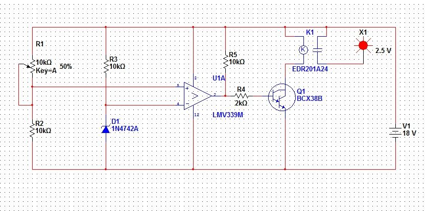
OK, I made one up in LabSim. I ran the design with 18V supply but it also works on 20V. Zener is a 12V reference. LM339 is 1/4 of a chip but I think these are also available as single comparators in an 8 pin package too.
|
|
March 03, 2013 by Ralphxyz
|
Wow, thanks mongo. Is this the K1 EDR201A24some sort of switch component? And what is X1? Is it terminated on +18v? Ralph |
|
March 03, 2013 by mongo
|
K1 is just a relay that I pulled out of the stock components list in Multisim. (I think I called it LabView earlier) Just about any 18 volt coil relay will work. 18 volt relays are hard to find though. A little modification and a 12 volt relay might be better in this case but some 24 volt relays also work down below 18 volts. The ERD201A24 is a DIP packaged reed type relay. Not really a power handler. X1 is a little perk that I use just as an indicator of output state. The program has several kinds and colors. Not really any part of the actual circuit. It is shown red here as it is in the ON state when I ran the test. |
|
March 03, 2013 by mongo
|
OH... The Darlington can be any power Darlington or a 2N222 and 2N2035 pair too. |
Please log in to post a reply.
|
Did you know that two resistors plus a transistor can be used to make a better voltage supply? Learn more...
|


Copyright © 2013 by NerdKits, L.L.C.