NerdKits - electronics education for a digital generation

You are not logged in. [log in]

NEW: Learning electronics? Ask your questions on the new Electronics Questions & Answers site hosted by CircuitLab.

Project Help and Ideas » 16 Buttons using one ADC input

December 11, 2011
by SpaceGhost
SpaceGhost's Avatar

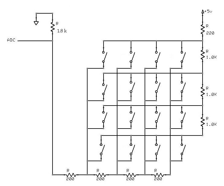
This is something that I had been working on for a while. I came across this concept a while back while researching keypad input circuits and how they can be used with a microcontroller.

Most matrix 4 x 4 and 3 x 4 keypads (telephone style and others) have 8 or 7 (respective) wiring connections - thus it usually takes at least 7 or 8 pins of a microcontroller to make use of the 12 or 16 inputs of a matrix style keypad.

However, I found out about a clever concept of using just one ADC input by wiring resistors across each row and each column connections on a keypad, providing different analog readings corresponding with each button when it's pressed that can be read by an MCU's analog port.

I haven't seen anything in the Nerdkits forums pertaining exactly to doing this, but there are a few articles about doing this on the web, mostly geared toward Arduino users. Different resistor values have been used, but for simplicity's sake I like the circuit and the values that are used here. By the way, my ADC readings are not anywhere near the readings shown with that circuit.

Other differences - I used a 1.8k resistor instead if the two 1k resistors in series connected to the positive reference. And I reversed the polarity of the voltage divider circuit - I have the 200 ohm resistor connected to the positive reference, and the 1.8 resistor to gnd. This gives me an ADC reading of "0" when no buttons are pressed.

I don't know arduino code and rather than try to decipher some of the few C examples that I saw, I started working with the Nerdkit tempsensor code.

First results didn't seem to work out too well - I experienced the "jumpy ADC readings," as discussed here, in this forum topic.

Another problem that I had to work through was that it seemed as though the microcontroller would sometimes "catch" values, as they fluctuated up or down... This would often cause improper readings on the binary outputs. Crappy pushbuttons I believed, may have made the situation even worse.

Instead of the telephone style keypad I was using I finally opted to put a row of 16 tactile pushbutton switches on a breadboard, then wired them matrix style. This way if I had a button acting funny I could replace it.

After constructing my keypad with resistors wired to the proper "row & column" connections, I hooked the "data" wire from the keyboard to PC0, loaded the tempsensors code to the MCU and began collecting ADC values for each button press... This information gave me the keypress parameters to set for the rest of the code.

To make a long story short, after much experimentation with code modifications I finally got a program that works very well with my set up. This code is based on a modified-version of Noter's modified-version, of the tempsensor project (see link above), added to some binary-coding code that Rick helped me with back when I first got my Nerdkit.

// adckey03b

// derived from "ADC_test.c - load on nerdkit with LCD" by Noter
//
//  Measure with 16 bit precision by oversampling ADC.
//
//   8468 bytes

#include <avr/pgmspace.h>
#include <inttypes.h>
#include <stdbool.h>
#include "../libnerdkits/delay.h"
#include "../libnerdkits/lcd.h"

// LCD stream file - enable printf in functions outside of main()
FILE lcd_stream;

// --------------------------------------------------------------------------------------------------------
int main() {

  // Set binary outputs

  DDRB |= (1<<PB5); // MSD 0001

  DDRB |= (1<<PB4);

  DDRB |= (1<<PB3);

  DDRB |= (1<<PB2); // LSD 1000

  DDRB |= (1<<PB1); // "5th" bit

  // initialize LCD display
    lcd_init();
    fdev_setup_stream(&lcd_stream, lcd_putchar, 0, _FDEV_SETUP_WRITE);

    // select AREF and mux ADC5
    ADMUX = 5;
    // enable ADC with Prescaler of 128
    ADCSRA = _BV(ADEN)|_BV(ADPS2)|_BV(ADPS1)|_BV(ADPS0);

    double temp;
    int32_t ADC_16bit;
    int i;

    uint8_t a;

    a = 0;

    PORTB |= (1<<PB5);
    PORTB |= (1<<PB4);
    PORTB |= (1<<PB3);
    PORTB |= (1<<PB2);

    while(true){

    ADC_16bit = 0;

    for(i=0;i<25;i++) {

    // start conversion
    ADCSRA |= _BV(ADSC);

    while(ADCSRA & _BV(ADSC)); // wait for it to complete

    ADC_16bit += (ADCL | (ADCH<<8)); // accumulate samples

    }

    delay_ms(50); // delay so that ADC doesn't capture a wrong value

    ADC_16bit=ADC_16bit>>6; // precision shift

    // calculate

    temp=9.0/5.0*ADC_16bit/65536.0*500.0+32.0;

    // show result

    lcd_line_two();
    fprintf_P(&lcd_stream, PSTR("%i  "), ADC_16bit);

    // binary conversion

    if( a & 1 )
    PORTB &= ~(1<<PB2);
    if( a & (1<<1))
    PORTB &= ~(1<<PB3);
    if( a & (1<<2))
    PORTB &= ~(1<<PB4);
    if( a & (1<<3))
    PORTB &= ~(1<<PB5);

    if ((ADC_16bit > 117) && (ADC_16bit < 121)) { // 1. ADC = 119

    //delay_ms(50);

    a = 1;

    }

    if ((ADC_16bit > 122) && (ADC_16bit < 125)) { // 2. ADC = 123

    //delay_ms(50);

    a = 2;

    }

    if ((ADC_16bit > 126) && (ADC_16bit < 130)) {//{ // 3. ADC = 128

    //delay_ms(50);

    a = 3;

    }

    if ((ADC_16bit > 132) && (ADC_16bit < 135)) { // 4. ADC = 133

    //delay_ms(50);

    a = 4;

    }

    if ((ADC_16bit > 143) && (ADC_16bit < 146)) { // 5. ADC = 144

    //delay_ms(50);

    a = 5;

    }

    if ((ADC_16bit > 150) && (ADC_16bit < 153)) { // 6. ADC = 151

    //delay_ms(50);

    a = 6;

    }

    if ((ADC_16bit > 157) && (ADC_16bit < 160)) { // 7. ADC = 158

    //delay_ms(50);

    a = 7;

    }

    if ((ADC_16bit > 164) && (ADC_16bit < 167)) { // 8. ADC = 165

    //delay_ms(50);

    a = 8;

    }

    if ((ADC_16bit > 182) && (ADC_16bit < 185)) { // 9. ADC = 183

    //delay_ms(50);

    a = 9;

    }

    if ((ADC_16bit > 192) && (ADC_16bit < 195)) { // 10. ADC = 193

    //delay_ms(50);

    a = 10;

    }

    if ((ADC_16bit > 203) && (ADC_16bit < 207)) { // 11. ADC = 204

    //delay_ms(50);

    a = 11;

    }

    if ((ADC_16bit > 216) && (ADC_16bit < 220)) { // 12. ADC = 217

    //delay_ms(50);

    a = 12;

    }

    if ((ADC_16bit > 248) && (ADC_16bit < 252)) { // 13. ADC = 250, 249

    //delay_ms(50);

    a = 13;

    }

    if ((ADC_16bit > 269) && (ADC_16bit < 272)) { // 14. ADC = 269

    //delay_ms(50);

    a = 14;

    }

    if ((ADC_16bit > 290) && (ADC_16bit < 294)) { // 15. ADC = 291

    //delay_ms(50);

    a = 15;

    }

    if ((ADC_16bit > 315) && (ADC_16bit < 319)) { // 0. ADC = 317

    //delay_ms(50);

    a = 0;

    PORTB &= ~(1<<PB1);

    }

    if (ADC_16bit < 113) {

    PORTB |= (1<<PB1);

    PORTB |= (1<<PB5);
    PORTB |= (1<<PB4);
    PORTB |= (1<<PB3);
    PORTB |= (1<<PB2);

    a = 0;

    }

    if (a > 0) {

    delay_ms(50);

    PORTB &= ~(1<<PB1);

    }

    if ((a == 0) && (ADC_16bit > 315)) {

    PORTB &= ~(1<<PB1);

    }

  }

return 0;

}

16 inputs on one wire. I have been playing with my set up for a few days now, just randomly pressing buttons when I'm around it... It hasn't failed or given a false reading yet running the code posted above.

If you do a similar version of this project keep in mind that it will surely involve some tweeking... I believe that the ADC results could vary in regards to different switches and even between different resistors that are of the same value.

As always, I'm always interested in people's questions, comments, suggestions and ideas for improvements.

Dave

December 11, 2011
by SpaceGhost
SpaceGhost's Avatar

I need to make a correction in what I said about my circuit modifications that I had made -

Upon examining the picture I posted the link to, I now see that I have my breadboarded keypad wired to gnd. and the + reference the way it's shown in the schematic - but I have the placement of the values of the 1k and the 200 ohm resistors swapped in my circuit. I still get usable values though, so I guess it doesn't matter too much!

December 11, 2011
by Ralphxyz
Ralphxyz's Avatar

So SpaceGhost do you have a schematic of your switch wiring?

Your project is very intriguing.

Seems like it might be usable.

Of course another method would be to use a Port Expander using I2C which would require two wires (pins) but you can daisy chain the port expanders so you could have lots of buttons.

Are you doing any button debouncing?

Ralph

December 12, 2011
by SpaceGhost
SpaceGhost's Avatar

Hello Ralph

I have my switches and resistors wired the way they are in this diagram - link

From what I have seen around the web, other resistor values will work for this circuit too. The main idea is for the MCU to be able to interpret the various resistance values outputted by the keypad, then "do something" in relation to which button was pressed. The code I posted was mainly to demonstrate how I have it working. There are surely other and probably better ways of writing the code... There may be other resistor value combinations that work better too.

I thought the same thing as I discovered information about the concept - that the idea is "intriguing." I intend to experiment some more.

The idea has been mentioned on some other AVR forums but I haven't seen it mentioned here on Nerdkits'. So, I thought I'd toss it on here for others to ponder and tinker with if they thought it was interesting too.

Input shift registers and I2C port expanders may be more desirable in some applications, but using an ADC/keypad may be a viable alternative with others. That could be an opinion of mine that is subject to change though.

As for "button debounce" I haven't done any hardware debouncing of individual switches. The 50 ms delay on line 70 took care of a lot of the trouble I was having with the ADC capturing false values as the button was pressed or let go.

My first experiments with the code produced unreliable and often buggy quirks with certain button presses... What I have posted here now seems to work pretty reliably, but I would bet it could be refined or improved even better. I'd love hearing other peoples ideas or comments. I've had fun playing with it...

With those extra pins available, I'm thinking about adding keypad "beep" next!

December 13, 2011
by Ralphxyz
Ralphxyz's Avatar

Hey SpaceGhost thanks for the link to the wiring diagram that is really cool, I like it.

Using one wire to the ADC for multiple buttons is very neat, those PIC guys are pretty clever ;-)

Ralph

December 21, 2011
by SpaceGhost
SpaceGhost's Avatar

I have now added beeps to the keypad. Each individual switch has an individual tone, except for the last four switches when I got lazy and used the same "note" for all four.

The tones that I used are the notes from the "Happy Birthday" program discussed here. I modified note "G1" though, because I though it was too low and didn't sound nice with the others.

Tone output is a short-duration "beep" for each button, whether the button is pressed quickly or held while pressed.

Here is how I have the resistors and switches wired -

alt image text

And here's the code -

//keybeep01
//
//   8866 bytes

// F_CPU defined for delay.c
#define F_CPU 14745600    // 8MHz

#include <avr/io.h>
#include <avr/interrupt.h>
#include <avr/pgmspace.h>
#include <util/delay.h>
#include <inttypes.h>
#include <stdlib.h>
//#include <stdbool.h>

#include "../libnerdkits/delay.h"
#include "../libnerdkits/lcd.h"

// LCD stream file - enable printf in functions outside of main()
FILE lcd_stream;

void play_tone(uint16_t delay, uint8_t duration) {
// delay is half-period in microseconds
// duration is in 10ms increments

// example: 440Hz --> delay=1136

 // duration = 2*delay * cycles (all in same units)
 // cycles = 10000 * duration / delay / 2
 // cycles = 100 * duration / (delay/50)
 uint16_t tmp = 100 * duration;
 uint16_t delaysm = delay / 50;
 uint16_t cycles = tmp / delaysm;

 while (cycles > 0) {
 PORTB |= (1<<PB1);
 delay_us(delay);
 PORTB &= ~(1<<PB1);
 delay_us(delay);
 cycles--;
    }

 }

 #define C1 166
 #define D6 425
 #define D5 851
 #define E5 758
 #define E6 379
 #define Fsh5 675
 #define G5 637
 #define A5 568
 #define B5 506
 #define C6 477
 #define D6 425
 #define G1 904

 //#define DUR1 40

 #define DUR2 20

int main() {

  // Set binary outputs

  DDRC |= (1<<PC4); // MSD 0001

  DDRC |= (1<<PC3);

  DDRC |= (1<<PC2);

  DDRC |= (1<<PC1); // LSD 1000

  DDRC |= (1<<PC0); // "5th bit"

  DDRB |= (1<<PB1); // tone output

  // initialize LCD display
    lcd_init();
    fdev_setup_stream(&lcd_stream, lcd_putchar, 0, _FDEV_SETUP_WRITE);

    // select AREF and mux ADC5
    ADMUX = 5;
    // enable ADC with Prescaler of 128
    ADCSRA = _BV(ADEN)|_BV(ADPS2)|_BV(ADPS1)|_BV(ADPS0);

    double temp;
    int32_t ADC_16bit;
    int i;

    uint8_t a;

    uint8_t b;

    a = 0;

    b = 0;

    PORTC |= (1<<PC4);
    PORTC |= (1<<PC3);
    PORTC |= (1<<PC2);
    PORTC |= (1<<PC1);
    PORTC |= (1<<PC0);

    while(1){

    ADC_16bit = 0;

    for(i=0;i<25;i++) {

    // start conversion
    ADCSRA |= _BV(ADSC);

    while(ADCSRA & _BV(ADSC)); // wait for it to complete

    ADC_16bit += (ADCL | (ADCH<<8)); // accumulate samples

    }

    delay_ms(30); // delay so that ADC doesn't capture a wrong value

    ADC_16bit=ADC_16bit>>6; // precision shift

    // calculate

    temp=9.0/5.0*ADC_16bit/65536.0*500.0+32.0;

    // show result

    lcd_line_two();
    fprintf_P(&lcd_stream, PSTR("%i  "), ADC_16bit);

    if (ADC_16bit > 116)

    b = b + 1;

    if (b > 2)

    b = 2;

    lcd_line_four();
    fprintf_P(&lcd_stream, PSTR("%i  "), b);

    if ((ADC_16bit > 117) && (ADC_16bit < 122)) { // 1. ADC = 119

    a = 1;

    if (b == 1)

    play_tone(C1, DUR2);

    }

    if ((ADC_16bit > 122) && (ADC_16bit < 127)) { // 2. ADC = 123

    a = 2;

    if (b == 1)

    play_tone(D6, DUR2);

    }

    if ((ADC_16bit > 127) && (ADC_16bit < 132)) {//{ // 3. ADC = 128

    a = 3;

    if (b == 1)

    play_tone(D5, DUR2);

    }

    if ((ADC_16bit > 132) && (ADC_16bit < 137)) { // 4. ADC = 133

    a = 4;

    if (b == 1)

    play_tone(E5, DUR2);

    }

    if ((ADC_16bit > 143) && (ADC_16bit < 148)) { // 5. ADC = 144

    a = 5;

    if (b == 1)

    play_tone(E6, DUR2);

    }

    if ((ADC_16bit > 149) && (ADC_16bit < 155)) { // 6. ADC = 151

    a = 6;

    if (b == 1)

    play_tone(Fsh5, DUR2);

    }

    if ((ADC_16bit > 156) && (ADC_16bit < 162)) { // 7. ADC = 158

    a = 7;

    if (b == 1)

    play_tone(G5, DUR2);

    }

    if ((ADC_16bit > 164) && (ADC_16bit < 170)) { // 8. ADC = 165

    a = 8;

    if (b == 1)

    play_tone(A5, DUR2);

    }

    if ((ADC_16bit > 181) && (ADC_16bit < 187)) { // 9. ADC = 183

    a = 9;

    if (b == 1)

    play_tone(B5, DUR2);

    }

    if ((ADC_16bit > 191) && (ADC_16bit < 198)) { // 10. ADC = 193

    a = 10;

    if (b == 1)

    play_tone(C6, DUR2);

    }

    if ((ADC_16bit > 203) && (ADC_16bit < 209)) { // 11. ADC = 204

    a = 11;

    if (b == 1)

    play_tone(D6, DUR2);

    }

    if ((ADC_16bit > 216) && (ADC_16bit < 222)) { // 12. ADC = 217

    a = 12;

    if (b == 1)

    play_tone(G1, DUR2);

    }

    if ((ADC_16bit > 248) && (ADC_16bit < 255)) { // 13. ADC = 250, 249

    a = 13;

    if (b == 1)

    play_tone(E5, DUR2);

    }

    if ((ADC_16bit > 267) && (ADC_16bit < 275)) { // 14. ADC = 269

    a = 14;

    if (b == 1)

    play_tone(E5, DUR2);

    }

    if ((ADC_16bit > 290) && (ADC_16bit < 297)) { // 15. ADC = 291

    a = 15;

    if (b == 1)

    play_tone(E5, DUR2);

    }

    if ((ADC_16bit > 315) && (ADC_16bit < 324)) { // 0. ADC = 317

    PORTC &= ~(1<<PC0);

    if (b == 1)

    play_tone(E5, DUR2);

    }

    if (a > 0)

    PORTC &= ~(1<<PC0);

    if( a & 1 )
    PORTC &= ~(1<<PC1);
    if( a & (1<<1))
    PORTC &= ~(1<<PC2);
    if( a & (1<<2))
    PORTC &= ~(1<<PC3);
    if( a & (1<<3))
    PORTC &= ~(1<<PC4);

    if (ADC_16bit < 116) {

    delay_ms(50);

    PORTB |= (1<<PB1);

    PORTC |= (1<<PC4);
    PORTC |= (1<<PC3);
    PORTC |= (1<<PC2);
    PORTC |= (1<<PC1);

    PORTC |= (1<<PC0);

    a = 0;

    b = 0;

    }

  }

return 0;

}

Everything really seems to work great. I am not getting any false readings on the binary outputs, the circuit even reacts well to quick button presses. Tone outputs are consistant.

The tones of course are easy to modify - someone might be able to come up with some prettier tones.

In fact, I believe an ideal application for one-wire ADC keypads could be as mini or toy organs or simple electric pianos. I think several ADC inputs could be used with several buttons wired for each imput.... Causes me to wonder what the potential could be. I do not know what number of switches the limit would be for wiring the switches matrix style with resistors and still function usefully. Additional "rows & columns" may be possible for the keypads themselves.

I think a musical instrument project could be a lot of fun, but I'm not very musical. I really wouldn't know which notes would be the best to use or how they should be arranged... I certainly couldn't "tune" the thing by my tin ear. If someone does do an organ or something (or has ideas about doing one), I hope they post details about the project!

Anyway, I'm still having fun playing with the keypad. I even have an actual use in mind for mine. ;)

Dave

Post a Reply

Please log in to post a reply.

Did you know that you can aim and fire a servo-controlled water gun from your computer? Learn more...