NEW: Learning electronics? Ask your questions on the new Electronics Questions & Answers site hosted by CircuitLab.
Project Help and Ideas » Telephone Keypad leads
|
November 02, 2011 by Dmnelson |
My grandmother is partially blind and has trouble using the television remote, so I decided to make her a remote using a telephone keypad. I thought it would be a simple thing of finding a common wire to power all of the buttons, but using a continuity tester I have only gotten 4 buttons to work. Is there something I am missing? |
|---|---|
|
November 02, 2011 by SpaceGhost |
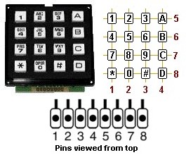
Hi Dmnelson Since you said that so far you have got only four buttons to work (verified by continuity tester), I am assuming that you have a 4 x 4, 16 button telephone style keypad? Coincidentally, I have been working on a remote (radio) control device that uses a 4 x 4 keypad. My remote is used to control a two-servo pan & tilt mechanism that I built for a miniature camera. Here's how my keypad works - looking at the bottom circuit board under the keypad, pins pointing up, left to right: Pin 1 - Common Pins 2 through 5 - these are the "row" pins. When any button in the first row of the pad is pushed, pin 5 and pin 1 (common) will have continuity. When any button in the second row of the pad is pushed, pin 4 and pin 1 will have continuity. When any button in the third row of the pad is pushed, pin 3 and pin 1 will have continuity. When any button in the fourth row of the pad is pushed, pin 2 and pin 1 will have continuity. Pins 6 through 9 - these are the "column" pins. When any button in the first column of the pad is pushed, pin 9 and pin 1 will have continuity. When any button in the second column of the pad is pushed, pin 8 and pin 1 will have continuity. When any button in the third column of the pad is pushed, pin 7 and pin 1 will have continuity. When any button in the fourth column of the pad is pushed, pin 6 and pin 1 will have continuity. How this used to distinguish or to read button presses as usable input data: When button "1" is pressed on the keypad, only pins 5 and 9 have continuity to pin 1. When button "2" is pressed on the keypad, only pins 5 and 8 have continuity to pin 1. When button "3" is pressed on the keypad, only pins 5 and 7 have continuity to pin 1. When button "A" is pressed on the keypad, only pins 5 and 6 have continuity to pin 1. When button "4" is pressed on the keypad, only pins 4 and 9 have continuity to pin 1. When button "5" is pressed on the keypad, only pins 4 and 8 have continuity to pin 1. When button "6" is pressed on the keypad, only pins 4 and 7 have continuity to pin 1. When button "B" is pressed on the keypad, only pins 4 and 6 have continuity to pin 1. ...And so, the pattern starts to become obvious. Some "pseudo code", to demonstrate how the microcontroller can use the keypad data to "do things": Hope this helps you out. I am hoping to get around to posting some pictures, and the code for my project some time this weekend. Dave |
|
November 03, 2011 by Dmnelson |
Thank you. It gives me a place to start. I look forward to your post about your project. |
|
November 03, 2011 by mongo 
|
Different telephone keypads work differently. Back when I worked for AT&T, the key pads were in an X-Y configuration. So the 1,2,3 were on one X line while 1,4 and 7 were on the same Y line. So when you press the number 1, two lines, X(a) and Y(A) were connected. If you pressed zero, it would connect the X(2) Y(4) lines. Others use the simple 10 or 12 signal wire format and some are BCD encoded where only four signal wires are used. (and one supply and possibly a ground) |
|
November 12, 2011 by Dmnelson |
http://www.reizenusa.com/prodManuals/REIZEN_manual_3055506.pdf That is the type of keypad I am trying to use. I have threaded out a little bit. But I need help making sense of it. Pin 1 Common to 3,6,9,# Pin 2 unknown Pin 3 Unknown Pin 4 Unknown Pin 5 This is used twice. With pin one, it activates button 3. However, it is common to buttons 1,2, and M1 Pin 6 Button 6 Pin 7 Button 9 Pin 8 Button # Pin 9 Button 0 Pin 10 Button 2 Pin 11 Button 1. I have been looking for a schematic but so far have been unsuccessful. |
|
November 13, 2011 by SpaceGhost |
Well, the keypad that you want to use is a whole different animal than what I have. In fact I believe the keypad that I have is either an obsolete part, or at least it's a unique one. My keypad is very similar in appearance to this one -
Except that the header pins on mine run along the top/back side of the keypad and I have an extra 9th pin. This "9th pin" is a "common" connection to any row/column connection that is made when a button is pressed. Every 4 x 4 16 button keypad that I have looked at online seem to have only 8 connection points - these points produce row and column connections corresponding to individual keypad button presses. I programmed a '168 MCU to encode my keypad's 4 x 4 (8 pin) outputs into a binary coded 4-bit output. I added a 5th output that is active (low) when any button on the pad is pressed. However, my code relies on that 9th pin "common" that only my keypad seems to have. I fear this makes my code as obsolete as my keypad. It's too bad too, because it was pretty simple to code. But I am not sure yet how to program an MCU to read the 8 pins that are only being tied to each other, and not another common connection that can be tied high or low... Hmmmm. Ah, but there is a solution, albeit I fear that it is not a cheap one. There is a chip, a 74C922 that will convert 8 pin keypad outputs to 4-bit binary outputs. Looking at the pin assignment for this chip,
I see that there is an "output enable" pin and a "data available" pin. I haven't researched this part thoroughly yet but I believe that the presence of these two pins means that I will be able to have the 5th output bit for "any key pressed", that I need in my project. At my dirt-cheap, not-supposed-to-sell-to-the-public-but-they-sell-to-me, electronics source, the 74C922 sells for $8.33. coincidentally this is the same shop that I bought my 9 pin keypad (they have only 5 left). I would rather be able to program an MCU to work with the 8 pin keypads... These keypads are very common, easy to obtain, and come in a variety of neat styles. Some of the membrane types look like they might even be fairly easy to customize with a person's own graphic overlays. I suppose that an input shift register could be used with 8 pin keypads to "talk" to a microcontroller. I haven't researched that option yet, as what I have (programmed MCU)works very well with what I got (keypad). Also, I would be adding another component that I don't have on hand. However since I just very recently became aware that my keypad does not appear to be what is now the standard architecture, that bothers me a bit. I would be willing to post the code for my keypad if anyone is interested, or think that it could help in designing another program that will work with generic 8 pin keypads. Or, does anyone knows of a clever way to make an 8 pin keypad behave like a nine pin one..? Dave |
|
November 13, 2011 by SpaceGhost |
Sorry Dmnelson, I got a bit carried away. I didn't mean to hijack your post! Your keypad is a 12 button keypad and has 11 pins or connection points - how are they arranged? Were you able to remove the keypad from the phone in one piece? Pictures of your disassembled unit could be helpful. Or, you might decide to invest in one of the other types of 12 or 16 button keypads that are available for hobbyists. Or, the switch logic of these "matrix" style keypads is pretty easy to duplicate. You could even make a keypad of your own using large tactile push buttons and switch caps - schematics are easy to find, with Google. |
Please log in to post a reply.
|
Did you know that LEDs (light emitting diodes) only conduct current in one direction, like normal diodes? Learn more...
|


Copyright © 2013 by NerdKits, L.L.C.