NEW: Learning electronics? Ask your questions on the new Electronics Questions & Answers site hosted by CircuitLab.
Project Help and Ideas » Photography club rating kit
|
May 05, 2010 by NK_EK |
Hi, It's a long time since I've been on the forums, so forgive me as I'm a bit rusty (OK. a LOT :-) I've been asked to build a kit for a photography club in our town that they would use in competitions to rate the photographs entered. It will consist of the following:
I have the following basic design in my head: For the Remotes:
Control box:
Could anyone please just point me in the right direction with tips and ideas:
Am I on the right track or am I taking the long way 'round? I know, it sounds fairly straight-forward, but keep in mind that I've never yet worked with external chips and especially interfacing them to the ATMega168 / 328, so any help or ideas will be truly appreciated. I'll have a look through some of the tutorial pages and some other projects to get some ideas as well. Thank you in advance Ernest |
|---|---|
|
May 06, 2010 by Rick_S 
|
Before I could begin making suggestions, or throw out ideas, I'd need to know more about the function of the device. Will buttons be pressed simultaneously? Will multiple buttons be pressed on the same remote? If these are used for judging, can only one 'vote' be cast per photo? If so, what would happen if someone pressed '5' multiple times for one photo? Is the display going to show a tally of the three remotes (a number between 1 and 15)? The project sounds like it could be very interesting and there are many supplemental chips that could probably aid the configuration. Rick |
|
May 06, 2010 by NK_EK |
Rick, Thanks for coming back & yes, I should've put more detail, but you made me think more about the practical things, so thanks!
This will be my first "real-world" project, so I'm pretty thrilled and as I said, I've not worked with interfacing other chips to the MCU, so will find that a welcome challenge. Thanks again for the help in advance. Ernest |
|
May 08, 2010 by Rick_S
|
Sorry it took me so long to get back to you... OK, for the five seven segment displays, you have a few options.
For a single micro-controller solution, options 2 & 3 would probably be best since you'll need other data lines for your input boxes. As for the input boxes, I would think you would want something along the line of 6 buttons. (Now this is just me thinking out loud :D ) 1-5 would be your rating buttons, each with a confirmation LED on the box. The 6th would be a Vote/submit button that would actually cast the vote for tally. This would allow the judge a chance to change their mind before actually submitting their vote. One way to do this, would be a micro-controller in each voting box that would set a status line for the main control box to let it know the vote is cast. You could then set 3 data lines for a binary representation of the vote. The Status lines from the 3 voting boxes could all 3 be run into a 3 input AND gate so that only 1 input would be needed at the main control box's micro-controller. This method would require 10 lines on your main control box micro-controller plus your output lines for your displays. Very doable for the 168. A setup like this would also allow for your 6-wire phone connector hookups (4 for the data, 1 for power, and 1 for ground) This would also handle Judge sway in that it could have all displays read zero until all 3 votes have been submitted. This would allow for honest individual judgement. I'm sure there is a more elegant method but that's what popped in my crazy old mind this morning. :D Hope that gives you some food for thought, Rick |
|
May 08, 2010 by Rick_S
|
As I was thinking a bit more, you'd probably need another button on the controllers for a reset... |
|
May 10, 2010 by avicell |
If you press '5' and the LED shows a '5', but change your mind to a '4', I wouldn't think a reset button is necessary since you haven't hit the 'submit' button yet. The LED would automatically update to show what you've entered. |
|
May 10, 2010 by Rick_S
|
My thought of operation... Judge has controll with 5 buttons. Master box controls a 7 segment display for each judge plus the 2digit display for total. All displays read zero Judges press thier vote buttons 1 thru 5 and an individual LED lights on their control box to indicate the button pressed. All three judges do this. However, their votes are not "cast" until they hit the submit button. At that time, the displays will show the individual judge vote as well as the judge tally. And, yes, avicell on further thought... you are correct. Because once the vote is "cast", that could reset the controller for the next vote. You would however need either a master reset on the control box to set it up to process another set of votes or a timed display that resets after a given amount of time has lapsed. This could be a very interesting project... Hopefully NK_EK comes back around to let us know how it went. |
|
May 10, 2010 by NK_EK |
Hi guys! Sorry, but I'm snowed under at work and didn't have any time to work on this project yet (and probably won't for a while). Thank you for some great ideas though! You've got the cogs turning. I'll probably be in a city where I can get some proper electronics spares, so I'll try to get my wishlist ready. Unfortunately though, one absolute requirement is that the kit must be as low cost as possible (they're basically an amateur club at this stage). Maybe later on I could look at the option of using more than one uC. What I did think of - to prevent judge 'sway' as you rightly mentioned - is to use your idea to have the displays all show a 0 until all three judges have made their decisions and only then display the individual scores as well as the total. It will then display these scores until the reset button is pressed. That's the hardware, but software-wise I think I'll have to rely on interrupts to get the input from at least one external A/D converter or to react on signals from it/them. The rest should be pretty straight forward. I would love to make it more professional by using those LED switches that light up as you press them, etc, etc, but as I said earlier - they want it as low cost as possible. Someone else charged them more than ZAR15000.00 (approx $2000) for a very basic system that does even less than what we've discussed! Anyway, I will get to it - hopefully within the next couple of weeks and will definitely keep you guys up to date. In the meantime, if you think of anything else, please feel free to post them. Thanks for help so far! Ernest |
|
May 14, 2010 by NK_EK |
Hi guys! I've got my wish list ready & ordered the parts, but was just wondering: can I use an ADC to connect the BUTTONS to the MCU? I was thinking of using 2 x CMOS 8-Channel Analogue Multiplexer chips (4051B) to connect the 15 buttons to, which will then bring the pins needed on the MCU down to a max of 8 (for the buttons) and 3 for the 74HC164 (CMOS 8-bit serial-in parallel output shift register) / 74HC595 (8-bit shift register) which will in turn connect to 5 x 4511B's (CMOS BCD to 7-Segment Decoder). 1 pin will also be used for the controller reset button (to zero the displays & reset program variables, etc), although that could also be connected to the last 4051B port (IF it can be used in that way - see below). So that gives me 12 pins used on the MCU, which SHOULD be entirely doable. Now, what I'm not certain of, is can an ADC be used in that way? Would the relevant ADC analogue pin go high on a button press - I presume sending a "1" or "on" to the digital output pin, or am I completely on the wrong track here? Also, can I connect these chips on any port of the MCU or can I only use certain ports for them (hope you understand what I mean)? Thanks again! Ernest |
|
May 31, 2010 by NK_EK |
Hi, I'm back - in between my work, so please bear with me. I tried connecting the various chips together over the weekend and see if I got something from anything :) - see something on the MCU being fed back from an ADC or turning on one of the LED displays, but alas, nothing. What I don't get, is how to supply the clock to another chip (the rest I'll get to later :). I've had a look at the datasheet of the MCU and it seems to me that I could - and I'm probably WAY off here - use a timer interrupt on one of the pins and then connect that to the CLK pin of all the relevant off-MCU chips (to get them all on the same clock). Am I on the right track or way off again? Looks as if I bit off a LOT more than I can chew at this stage, but I would REALLY like to learn how to do this. Thanks for the help guys. Ernest |
|
May 31, 2010 by Rick_S
|
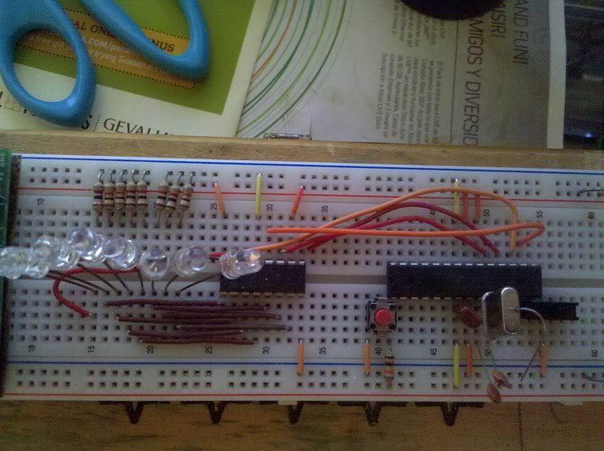
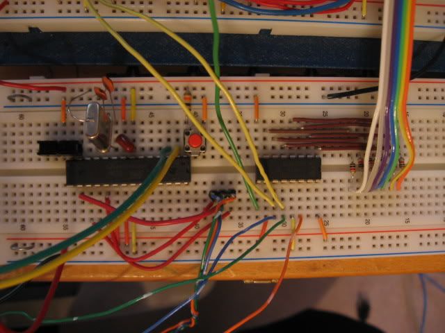
1st, if you are driving standard 7 segment LED Displays, you don't need the 4511's as the 74HC595's can drive them directly. Of course, that's your call. Here is a snippet of code I got off the web and modified to play around with a 74HC595. This code will make the led's tied to the 595's outputs scan back and forth then alternate. The 595 is connected to the microcontroller via the spi interface. Here is a photo (Sorry taken with my cell phone) of the 595 setup for that particular program. Note the 4 wire SPI connection to the micro and direct connection with current limiting resistors on the LED's.
As for the multiplexing chip, I've never had to mess with one of those. I'd probably re-invent the wheel and use another microcontroller to serve a similar purpose. Money wise they'd probably be very little more in cost and I'd have complete control on how I wanted it to work and interconnect to the main controller. Hope that helps a bit or gives you some more food for thought... :) Rick |
|
June 01, 2010 by NK_EK |
Rick, Thanks! Certainly some food for thought there. I've decide to go into reverse gear a bit & go back to the bottom of the ladder. I've set up a 7-segment display directly connected to the MCU and got that working with not too much fuss. Next step will probably to try to get a 4511 hooked up to the MCU and drive the display that way. I know, it may seem like the long way round here, but these steps help me get to know the equipment I'm trying to use & how to address them from the MCU. In the meantime, I looked through the MCU datasheet - AGAIN! - and found something very interesting that might just do exactly what I'm looking for (providing the clock & communications to external chips). Pin PC4 & PC5 can be used as TWI pins and provide a clock (PC5) to multiple external devices & PC4 can be used as the data bus. The advantage of this is that you only use 2 pins on the MCU instead of 4 (for SPI). There are obviously some trade-offs between the 2, but I think for my purposes TWI should be fine. Anyway, I've wired it out, but did not have time yet to play with the programming, so I'll give that a try as soon as possible and let you guys know. BTW, I'm using the 8-bit shift register because I can connect up to 8 separate 4511's to it (using only 3 pins on the MCU - 2 for TWI & 1 for RESET). Then I use 4 pins on the MCU common to all 4511's to drive the 7-segment displays - thus 7 pins to drive 8 7-segment displays (in my case I'll only use 5 displays). Thanks again for the help (and I'd obviously appreciate some comments :)! Ernest |
|
June 02, 2010 by Rick_S
|
If you use the 595's without the 4511's, you would only need 1 595 per display using 4 wires on your micro without the need for the 4511's. Plus you would add to the simplicity of your code in that each of the 595's 8 bits would provide the output to 1 display. So five 7-segment displays would need 5 bytes sent out to the 595's, then latch them and your displays are set. I'm also not too sure if you can use the Two wire interface the way you are wanting to. While it may be possible, I've never seen anyone use it like that. It is most commonly used to communicat with devices that follow the I2C protocol. Another question, How big are your displays. Do they have a larger current draw? If so, you may need to add some transistors to drive each segment. I don't know if you got displays that could be seen from across a room or if they are just your normal run of the mill 1" or smaller displays. Keep us updated, this is an interesting project. Rick |
|
June 02, 2010 by NK_EK |
Thanks, I didn't think of it that way, but just to be sure - what you're saying is that I would only need 4 pins on the MCU to drive ALL 5 displays (using the SPI method) instead of the 7 as in my last post? This is definitely something I didn't think of. Good to have guys with experience around :) I got the idea for the 8-bit shift register and the TWI setup from JKITSON's tractor sled project. It looks as if the 74HC164 can connect to the MCU using the TWI setup. The displays I'm using are the normal 1" displays, so there should not be any other components necessary (except the resistors). Thanks for the ideas! Ernest |
|
June 02, 2010 by Rick_S
|
You could drive even more displays than that if you chose to. The 595's just daisy chain from one to the other. As for TWI, I don't doubt that it could be used that way, I have just never messed around with it other than using it with I2C devices. |
|
June 02, 2010 by Rick_S
|
I was browsing the web and came across this board. It is a 4 digit 7 segment display board driven by 74595's. Rick |
|
June 05, 2010 by Rick_S
|
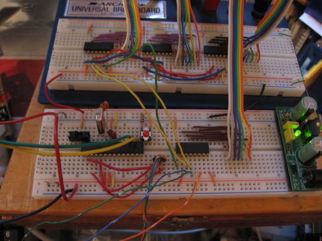
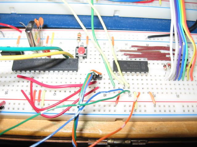
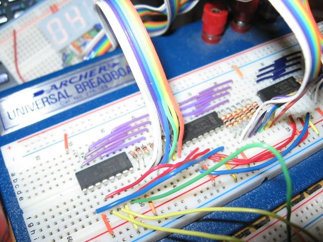
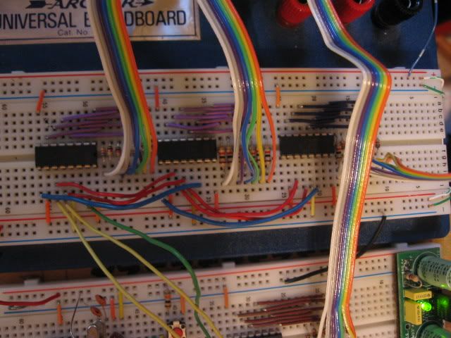
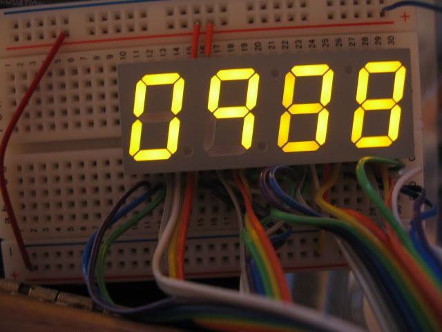
Ernest, Your project got me to pull my 595's from my parts drawer and start playing with them. Here's what I have... Hopefully it will be of some value to you. The following code will count from 0 to 9999 then reset and continue indefinately. The micro controller (I was using an ATMega328) sends data via a 3 wire connection to 4 74HC595's daisy chained together. Each 74HC595 drives a 7 segment display. Here is the Code... Photo's of my sloppy setup follow the code :)
Rick |
|
June 07, 2010 by NK_EK |
Rick, Thanks again! Looks like SPI is definitely the way to go for the displays at least. I came across another chip - MCP23016/7 (a 16 port I/O extender) which uses O2C / TWO to communicate with the MCU. This will be very helpful for the buttons, so I'm trying to get hold of 1 or 2 to play with. I will let you know how it goes. Thanks. Ernest |
|
June 12, 2010 by NK_EK |
Rick, I'm winning!! And in no small part thanks to you! I'm starting to understand the SPI interface & have played with getting 2 displays running with 2 595's (took a while for me to figure out the cabling & that the closest 595 to the MCU will be the one addressed last in the code, but the light eventually went on :-). I think I'll be able to get the displays running now. Now I'm just waiting for the MCP23016's to get here so I can start playing with the TWI for the buttons. I'm starting to get some more cool ideas to add to the final setup, so stay tuned! I'm like a child with a new toy! Thanks again for the help! Ernest |
|
June 12, 2010 by Rick_S
|
Great! I've had those 595's sitting in my parts drawer since last fall. My intent was/is to make an LED Array using them I just hadn't gotten around to figuring out the code to make them work. So thanks to you and your project, it was just the kick in the backside I needed to experiment and do a little self learning as well. That's one of the things I love about this community, it sparks ideas and thought. All within a friendly forum. Keep us updated, Rick |
|
June 13, 2010 by NK_EK |
Rick, Just a quick question: in your example and code I see that you cannot address each display individually (could be wrong though). As far as I understand, you have to set the CS / SCLR pin on each 74HC595 to be able to address it directly / individually (again, could be wrong). This would normally mean that you would use one pin on the MCU for each 595 to make it addressable individually. Would this design help to address that? I've now found the joy of the 595 ;-), so I was wondering if I could use one to drive the rest of the 595's driving the LED displays. I could then use the already set up SPI bus to control at least two 595's at any one time - the 'main' one (controlling the CS / SCLR pins of the rest) and the one being addressed directly. This way, I would not have to use any additional pins on the MCU for this.
Anyway, let me know what you think... Thanks Ernest |
|
June 13, 2010 by Rick_S
|
I've never tried anything like that, like I said in my last post, It was your project that got me fooling around with it. Is there a reason you couldn't send the full array's worth of data each time you refresh any display? By doing that, you wouldn't have to worry about individual latches. You were only talking about using 5 displays right?? |
|
June 13, 2010 by NK_EK |
Rick, Yes, I'm only using 5 displays and sending all the data each time isn't a problem, but I was just thinking. In fact, if you use one more pin on the MCU (e.g. PC0 in diagram above) to control the CS / SCLR of the "main" controller 595, you could address only one 595 at a time, or as many as you like. You would set the "main" CS high and send the data to enable the CS on the 595 you want to send the data to, then set the "main" CS low again. Then you can send the data to the other 595 with its CS set high. Repeat the CS sequence for the "main" 595 and you can then switch between 595's as you like or need. It may make things a little more complex, but I think also more functional as you could now basically (in theory at least) address any one pin (thinking of your LED array idea?). Anyway, just thinking aloud. Will keep you up to date. Ernest |
|
June 14, 2010 by Rick_S
|
I could see doing that if timing was a factor and there wasn't enough time to send out the data to all the shift registers. As for the led array, my plan was to keep it simple like the NK guys did and have 595's directly wired to the columns then use another with driver transistors to switch between rows. It would require a complete re-wiring of the array to make all the columns the same (either common anode or cathode). I do agree with you that it most likely could be done but also agree when you said it would be more complex. Rick |
|
July 15, 2010 by Rick_S
|
Hey Ernest, It's been a while, and I was wondering how the project was going. Did you get it done? Still a work in progress? Any cool photo's to share? :D Seriously, I hope it's all going good. I know sometimes the projects get the back burner for a while. Rick |
|
July 16, 2010 by NK_EK |
Hi Rick, Yes, unfortunately, this one has also had to be postponed for a while. I'm very busy at work and don't really get time to sit and play. I think I've got most of it figured out. Still waiting for my MCP23S17's to get here though, then I'll probably have to start figuring things out all over again - it'll use interrupts & SPI bus, etc, etc. I will definitely let you know as soon as I'm again able to play with this project. Thanks Ernest |
|
August 04, 2010 by NK_EK |
Hi, guys! I'm back - in between projects at work, but I'm trying to get this one done. Strange thing: Using SPI, I can drive the 595's to get the LED displays showing exactly what I want it to. I connected 6 buttons (1 - 5, and a reset button) to the MCU and it works 100%. Next I connected the MCP23S17 onto the SPI bus, but nothing happens - I can't read from it and - it seems at least - I cannot write to it. I'm using basically the same code as you did in your example code above, with a small change here and there (to enable the addressing on the MCP23S17, etc). It seems that when this chip is also connected on the same bus as the 595's, the 595's also stop working as they should. So, now I'm completely confused (not that that's too difficult :-). I'm considering running the MCP23S17 via I2C if I can't get this working, but I'd prefer running all the chips on the same bus as I will not have a lot of space on the PCB's (2 in total - 1 'main' board with the MCU, MCP23S17 & 1 'daughter' board with the LED displays & 595's) to run additional connectors. Anyway, just thought I'd keep you guys up to date. (I'll try to upload photo's of my test setup for the MCP23S17 so you could comment). Thanks Ernest |
|
August 04, 2010 by Rick_S
|
While the 74hc595's work well with SPI communications, technically they are not SPI devices. You should be able to get both working on the same bus however, you will need to provide separate enable lines for each and most likely have to write a different communication function for the port expander or at the very least do some serious modification of the existing function. The port expander requires an id byte be sent to it prior to it working so it knows you are talking to it as shown in the datasheet. One thing I'd do if I were intent on using the port expander as you are, and that would be to write a stand alone program just to control it similar to what you did for the 595's. Once you can confirm it is working by itself then you can 'merge' the two together. Good luck, and keep us updated. It's definately sounding interesting!! Rick P.S. If you opted to go with the I2C bus, I believe you'd have to get a different chip. Unless I read the datasheet wrong, the MCP23S17 is SPI where the MCP23017 is I2C. |
|
August 04, 2010 by NK_EK |
Rick, A BREAKTHROUGH!!!! I can write to the MCP23S17 & switch pins on & off (connected LED's to them & they work)! So at least I'm sure my comms work. Now I just need to figure out how to read from the chip, 'cause that's actually what I want to use it for. But at least we're getting somewhere. It seems (NOTE 'seems') that you need to explicitly set the MOSI & SCK pins on the ATMega168 to output AND LOW (knew about the output, but figured out the LOW). I just set them as output and never bothered to set them high or low. Not sure why it makes a difference, but I'm GUESSING it has something to do with the tri-state 'feature' of the pins. Any ideas? Anyway, I'll slog along & keep you up to date. Thanks for the help & ideas! Ernest |
|
August 05, 2010 by NK_EK |
Hi guys! I'm struggling with this reading of the MCP23S17. I can write to it without any problem, but just cannot seem to get the input back into the ATMega168. Here is my test code: I am open to any suggestions of nudges in the right direction. I googled SPI and found an example on a sight called ermicroblog - or something like that. I used that as an example and copied some code from it. I tried to play with some interrupts as well, but that's also not working - although not a major issue as I'll probably not need it. This one seems to have me stumped (maybe it's all the late nights / early mornings I spent trying to figure this out :-). Anyway, now I'm off to bed... |
|
August 05, 2010 by Rick_S
|
Looks like you missed a snippet of the code you sourced from ermicroblog (BTW, I love that website it was where I learned how to play well with the 595's). In their original source, there is an operation you missed in your read function. At line 27 in the source I copied from their site, they send a dummy byte to read the data. It was explained a little farther down in the text like this: The SPI_Write() and the SPI_Read() function is used to do the write and read to and from the MCP23S17 SPI slave. As you’ve seen from the SPI_Read() function code above; because the SPI slave could not initiate the data transfer that’s why the SPI master has to initiate the data transfer by sending the dummy data 0×00 to the SPI slave in order to read the SPI slave data. I don't know if that's the fix or not, I have no way to test it but it might be worth a shot... Rick |
|
August 05, 2010 by NK_EK |
Rick, Thanks. I've not had a chance to test it yet, but will asap. I did previously have that code in, but it still did not work, but I'll give a try again. In fact, I found another site that uses the same logic. It makes sense also, because - as they explain - the slave device on the SPI bus is in fact a glorified shift register and therefor, to push the data I need from the slave device onto the SPI bus and into the MCU, I need to send something else - most often a dummy / blank byte. In addition, they also suggest you put a 'delay_us (3);' just before you send the dummy byte. This is apparently to give the slave device a chance to get the data byte requested ready to transmit. Now, they use two Atmel MCU's on the SPI bus, so I'm not too sure if it's only necessary between two MCU's or if for any other SPI slave devices as well. I will test and come back to you. |
|
August 19, 2010 by NK_EK |
Hi guys! It's been a while... It's working - both the 595's as well as the MCP23S17 (very nice chip btw). I've finally managed to sort out most of the programming issues and have started to build the kit - homemade PCB's & all. Programming is not quite perfect yet, but at least it's working. I'll post some pictures as soon as I'm back from a week's break. Enjoy! |
|
October 04, 2010 by NK_EK |
Hi guys! Me again. I finally got the hardware side & the most difficult part of the programming done (addressing the various chips, etc), but I'm stuck with this one thing. I know I can do this the long way, but there must be a shorter way? My programming is very rusty (really only properly programmed in High School), so I'm trying to pick up as I go along. This is a snippet from my code: I want the array to be global so that I can use it whenever, wherever. BTW: BLANK is defined as 11 Any pointers, please? Thanks Ernest |
|
October 05, 2010 by NK_EK |
Hi, Here are some of the pictures of the hardware. Feel free to comment :-) Main board without any components:
Main board with components:
Display Board:
Boards connected:
This is my first project so be kind :-) I'll post pictures once everything is done. Cheers Ernest |
|
October 05, 2010 by Rick_S
|
Wow, Earnest, looks good. Home etched I'm guessing. How did the double sided etching go? What method did you use? The boards look pretty good. It's pretty neat to see your project progressing as well as it has. I don't know if it'll bite you or not, but it's good design practice to place a couple of capacitors (normally around 22pf) from the each crystal lead to ground. The solderless breadboards have enough "built in" capacitance to work but a printed board may not. Also decoupling capacitors at the power lead of the ic's are also a good idea. Just giving you some food for thought. Looks real good though. I bet you are eager to get it done :D Rick |
|
October 06, 2010 by NK_EK |
Rick, Thanks! I forgot to put up the picture of the Power board - will do that as soon as I'm back home. What I've done there, is put the capacitor that we put between the 5V & ground on the breadboard (pins 7 & 8), on the power board, so it should smooth out the supply for the entire system. Not too sure about the decoupling caps & the ones for the crystal though, but I'll keep it in mind for the future (so far everything seems to be working as it should). As far as the PCB's go, I used pre-sensitized boards, printed the two sides on Laser Printer transparency sheets and then just exposed to some good, intense light (normal light with strong bulb is fine, i.e. no need for expensive Ultra Violet, or some other kinds of lights). I then developed them & etched them with Sodium Persulphate. Just for good measure, I also soldered all the tracks - not sure if it made a difference, though. Anyway, I had a couple of flops - first time ever trying to do this - and even the final ones aren't perfect (don't have a drill press, so had to drill everything with a hobby drill and you can't always keep it straight up). For the via's, I used some excess wire that I cut from the resistors, LED's, etc to make the connections between top & bottom layers. Probably not the best way, but it works. Anyway, RE my previous question about global arrays, I decided to take the long approach - not using the array approach. It works very, very well, so I'm happy. Now just to figure out a simple way to debounce the RESET switch - it works, but sometimes takes a log time to reset. All I can figure is it must be debounced somehow in S/W. Thanks for all the help so far. I'm already looking forward to a next project (don't have one yet, but I learned quite a LOT!). Ernest |
|
October 09, 2010 by NK_EK |
Hi, Here is the pictures I promised of the Power Board (Top & Bottom) and some pictures of the final product. Power Board - "Top"
Power Board - "Bottom"
Main Box - Front
Main Box - Top - RESET Switch
"Remotes"
I delivered the kit and luckily they seem quite happy. Thank you all for your help & especially to Rick. Without your guidance & help, I would still have been struggling right at the start. Thanks Ernest |
|
October 10, 2010 by Rick_S
|
That looks real clean and well put together! Great job Earnest... I especially like the remotes they look very good. I still worry about the lack of filter capacitors but if it works it works right! I must say I'm very impressed at your build.. I can tell you put a lot of thought into the layout and design. You also did a great job on the cut outs in the plastic boxes... mine never seem to come out that clean looking. :D Rick |
|
October 10, 2010 by Ralphxyz 
|
Ernest, this has been a fascinating project, thank you. How did you make those remotes? Could you provide a little detail, are those capacitive touch buttons? Ralph |
|
October 10, 2010 by NK_EK |
Rick & Ralph, Thanks! Rick, can you please provide a little more info on the filter capacitors? Not sure what they're for or where to connect them (yes, stupid, I know). Is the one I used on the Power Board not something similar? Also, luckily you didn't see the cutouts up close :-). Ralph, The remotes each have a small PCB in it with 5 tactile switches on each. Using the 6-wire RJ-12 cables, I have 1 wire for each button and 1 left for a common GND (the only drawback is that the individual wires are VERY thin, so they are quite tricky to work with - maybe next time I'll rather use RJ-45 cable). I used 3 x 3m RJ-12 cables for the 3 remotes that plug into the main box. That then feeds into the MCP23S17 I/O extender chip which then in turn "talks" to the MCU over SPI. The MCU then takes the input and sends the output - also over SPI - to the 5 x 74HC595's which connect to the 5 x 7-segment LED displays. Hope that helps. Have any of you had any experience with the MAXIM MAX7221 "serial input/output common-cathode display drivers" (can drive 8 7-segment displays or up to 64 individual LED's from one chip)? Thinking of using them for any future versions of this projects. Thanks Ernest |
|
October 10, 2010 by Rick_S
|
While the singular capacitor (I'm assuming it's the 100nf cap) will help, depending on what your input supply is, may not be enough. I would assume you are using some sort of wall wart power adapter. When these are taken apart, I've seen some that do nothing more than rectify a transformer to DC with diodes. This creates a pulsed DC that turns on and off 120 times/sec in the US with 60Hz AC (once at each half cycle called the zero cross). This can can require more than a .1uf cap to filter it out. Commonly you have combinations of larger capacitors with the small ones. The larger will help with the drop between cycles (as the drop occurrs, the capacitor discharges to keep the power on). The smaller ones will help filter out stray interfereces in your power lines. That is why it is important to keep them as close to the power pins of the IC's as possible. For instance say your SPI is communicating at 100Hz, the traces on the board will act as an antenna and "broadcast" the on/off pulses of the serial communication. Adjacent power traces can "recieve" these signals and cause confusion in the IC's they power. This can cause erratic behavior in the microcontroller or other IC's. The "filter caps" will help reduce/eliminate this problem. Hope I helped clarify and didn't just muddle it up more :D Rick |
|
October 10, 2010 by Ralphxyz
|
Ernest, is your MCP23S17 I/O extender chip code publish in this thread? For that matter do you have a final version of your code? Just the other day I was looking at I/O extender chips and thinking about what to do with them I was following a Instructables on i2c and 7 segment displays. Between all of the threads here on Nerdkits and around the Internet I hope to understand i2c some day. Rick, could/would there be capacitors in parallel on the power lines? Not sure I understand where to use the different size capacitors. Ralph |
|
October 10, 2010 by NK_EK |
Rick, OK, thanks. Muddled a bit, but the light's breaking through - slowly. So, if I understand you correctly, it would be better design-wise to have a 100nf cap (or something similar) connected to the positive (+5V) and GND pins of EACH IC? Makes sense, I just want to make sure I understand. Also, the .1uf "filter" cap - would that be the same type of cap as the one in the NK, and would it be connected the same way (ie between +5V and GND)? Or would we use one that is in-line (right word?) only on the +5V Rail? Thanks Ernest |
|
October 11, 2010 by NK_EK |
Ralph, I'm at work now & my code, etc is on my home computer. I will post the SPI code as soon as possible. In the meantime, you could have a look at my post on 5 August above & Rick's response, my final code looks very similar to that. The IC I used is the MCP23S17 (note the 'S'). This is the one that connects to the MCU with SPI (NOT TWI!). For TWI/I2C you would use the MCP23017 as in the instructables post. Thanks Ernest |
|
October 11, 2010 by Rick_S
|
100nf = .1uf... sometimes I use the two interchagably... I wasn't trying to be confusing. I was just guessing that the single capacitor I saw on your power board was the one provided in the Nerdkit that is usually placed between pins 7 & 8. That is a .1uf capacitor. What I was stating that it is common practice to place multiple capacitors at the power supply, and at least one "filter" capacitor (could be like the .1uf in the NK) at the power input of each ic as close to the ic as possible. The basic schematic for the voltage regulator from a datasheet I had shows a capacitor on both the input and output sides.
Take a look at any commercial circuit board, you'll see a small capacitor (almost always surface mount on modern boards) at the power input of many of the IC's. The more data lines the circuit board has and the faster it runs, the more important these become. Or if the board is used in an environment where there is a lot of elecrical noise, this can be picked up by the traces of the circuit board. Granted, for your projcet, out side sources of electrical noise probably won't be a factor. The power supply capacitors on the input side of the regulation circuit can vary based on the noise level of the power being fed into it. You may want larger capacitors if the input power is real noisy (for instance power derived from a small crank type generator), or very small ones if the input power is anticiapted to be very clean (like that from a battery). I generally use something in the 10uf to 470uf range for my input side (depending on if I know what my source power is from or not). This takes care of most of the drop outs in the input power. I then use the small .1uf caps (sometimes on both sides of the regulator) to help filter noise. Again, since your board works as intended I wouldn't worry a lot. However, if for some reason, it starts giving some erratic displays, odd responses, or locks up, the caps may help. Other than that, it's just some food for thought for your future projects. Rick |
|
October 11, 2010 by NK_EK |
Rick, Thanks! Certainly some food for thought and something to keep in mind for future projects. Sorry, I did think at some stage that the .1uf and 100nf cap values were the same, but forgot about it again (probably a sign of impending old age :D ) Anyway, yes, the board is working as expected - and I'm very happy that it does - but any tips and tricks I can pick up along the way to polish my design skills & to make future designs & projects more reliable, are always welcome! Thanks again! Ernest |
|
October 11, 2010 by NK_EK |
Rick, You also said before that it is good design practice to put 1 capacitor on each leg of the crystal. At the risk of sounding stupid - nothing new - can you please explain the reason for that? I'm trying to Google that too, but nothing yet ... Thanks Ernest |
|
October 11, 2010 by NK_EK |
OK, found something in the ATMega168 Datasheet - right under my nose - p31. They suggest anything between 12-22pf. Just need to make sure - they're the same "type" as the ones we get with the NK, right? Thanks |
|
October 11, 2010 by Rick_S
|
I don't know that type is super critical for the crystal caps (or other ones for that matter). |
|
November 12, 2010 by BobaMosfet 
|
NK_EK- First, let me congratulate you on your beautiful PCB and work. You designed your product with thought and care, looking to understand how each component works and then integrate them. My hat is really off to you, because you have achieved more than most interested in electronics ever will. The full design & engineering cycle: idea, design, sourcing, schematic, breadboard testing, PCB manufacturer, PCB population, enclosure. I don't believe that can be overstated enough. All of us who climb this mountain are proud of your accomplishment and appreciate of your travails getting there--- Bravo! Rick- Great job sticking in there with all the help. I've been away a while, job considerations viciously pull at all my time, and I had a bit of a fiasco whereby my beloved wife wiped out my entire lab and inventory of parts (honest mistake, but still expensive). Just now finally got lab put back together (and now with padlock on door). To answer the capacitor .v. crystal question--- Use 20pF as this is the ideal capacitor value for this particular crystal at the fundamental frequency it's being run at. They help 'tune' the crystal (related to ESR) to help it maintain frequency. If you aren't experiencing any problems without them- don't worry about it. I add these capacitors as a rule of thumb for me. BM |
|
November 14, 2010 by NK_EK |
BobaMosfet, Thank you for the kind words. I spent quite a few late nights / early mornings on this project to get it finished in time. I also had a couple of strange issues which in the end turned out to be very subtle (right word?) shorts which were very difficult to detect. I almost thought I had to redo the entire PCB or order some more components! Luckily everything got sorted out & it's working as planned. In the meantime, they asked me to tweak some settings on the system and I found it very easy to quickly plug in the programming header, change the programming jumper and load the new program - took me all of five minutes! Thanks for the tip on the capacitors - I'll definitely keep this in mind for any future projects (nothing new lined up yet, but hopefully I'll start playing again soon). Thanks again also to Rick for all the help! Ernest |
|
December 12, 2010 by Swiz747 |
Rick_S, I tried duplicating your setup in your 5th post but with no luck.
|
|
December 12, 2010 by Swiz747 |
forgot to add the problem... it either stays always on or it flashes all of a sudden then back to solid on. Is there anything i did wrong with the setup? |
|
December 13, 2010 by Rick_S
|
It's really hard to tell (all the wires are the same color) which wire is going where. From what I can see, you have the wires from the micro to the 595 connected as such If I'm correct in how you have it wired, you got two wires flipped. The correct connection would be this. Other than that, I don't see anything jumping out that would be wrong. Rick |
|
December 13, 2010 by Swiz747 |
o wow, thank you so much rick! i got it working! you were right i had the two wires flipped. |
|
December 13, 2010 by Rick_S
|
No problem. Glad you got it going. |
|
November 22, 2011 by missle3944 
|
Rick, Im using your first set of code in this forum to run a stepper motor. Like this But for some reason it goes 1234 and then 4321. I am also confused on the code |
|
November 22, 2011 by missle3944
|
Sorry I mean't this It also looks like it doesnt turn on pin Q0 on the 595 only pins Q1 Q2 and Q3.Im confused -Dan |
|
November 22, 2011 by Rick_S
|
You lost me as to what you are asking for. The code I posted above was just for LED's. The loop you show at the end of your 1st post was to do a larson scanner (Knight Rider) type scan one pass back and forth. The other section of my 1st program was to alternate between the led's. Beyond that what were you trying to ask? BTW, steppers can draw a large amount of current. If you aren't now, you may want to use transistors to drive the stepper itself. Rick |
|
November 22, 2011 by missle3944
|
Rick, Sorry I didnt clarify :P What I'm asking is how do I have the shift register just loop this: Because when I tried it for some reason the first pin on the 595 to go high was the QD output. And then when I run the code it loops QD QC QB QA and then it goes back up the ladder and writes QA QB QC QD. So my question is not really on the stepper motor. I have that already worked out fine. Its on the code and just how to get the pins to loop and not to go back and forth. I'm using a ULN 2803 transistor array to drive the stepper motor. and I have the shift register driving the inputs. -Dan |
|
November 24, 2011 by Rick_S
|
In your code you are showing a single pin of the shift register going high. Since the ULN2803 inverts it's outputs and sinks current, wouldn't you need to have the energized coil a low and the non-energised high? In other words, invert your byte so instead of having.. you'd have and shift the zero. See if that helps. Rick |
|
November 25, 2011 by Rick_S
|
Dan, Did you get a chance to try that?? Rick |
|
December 02, 2011 by Rick_S
|
Did that work for you Dan? Rick |
|
December 02, 2011 by missle3944
|
Rick, Sorry for not getting back to you in a while :p I think it is the shift register code that I'm having problems with because the code im using alternates from left to right which makes the motor just stutter back and forth. I have used the transistor array successfully by just having the transistor inputs connected to 4 pins from the MCU so now I'm trying to transfer it over to shift register just for yucks. Though I just finished soldering a cool LCD connector but I'll take some pictures of it on Sunday and post them, it was a real pain to solder but it helped me gain experience. I used some old IDE pin headers to fit into the breadboard and then another set to go into the LCD pins and a ribbon cable in between to allow for more mobilization of the nerdkits LCD -Dan |
Please log in to post a reply.
|
Did you know that inductors try to keep their current constant over short periods of time? Learn more...
|


Copyright © 2013 by NerdKits, L.L.C.