NEW: Learning electronics? Ask your questions on the new Electronics Questions & Answers site hosted by CircuitLab.
Everything Else » Mounting the Nerdkit
|
June 04, 2009 by DavidSimpson |
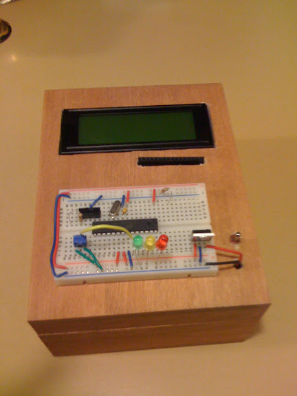
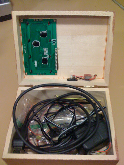
For convenience, I mounted my Nerdkit on the lid of a cigar box. See the photo below. I got the cigar box from Michael's craft store. The breadboard can be mounted on the lid by simply removing the paper from the back of the breadboard, revealing the adhesive backing. I mounted the other components using foam mounting tape (also available from Michael's, or from an office supply store). The LCD display required several layers of foam mounting tape to allow room for the pins on the back of the LCD. The battery is held in a 9V battery holder (available from Radio Shack) and is also mounted with mounting tape. The Nerdkit spare parts, wires, and cables can be stored inside the cigar box.
|
|---|---|
|
June 04, 2009 by DavidSimpson |
Also, I added felt pads to the bottom of the cigar box to keep it from scratching furniture. -- David |
|
June 04, 2009 by dylanjkj1997 |
Nice!!! Looks awesome! I should try this! |
|
August 31, 2009 by DavidSimpson |
I just added an on/off switch. I got a SPST toggle switch (Digi-Key #CKN1549-ND) and drilled a mounting hole for it into the lid of the cigar box (along with two smaller holes for wires) next to the battery. I then ran the + (red) battery wire through one small hole and soldered it to one lug of the switch; I soldered one end of a 22-gauge solid wire to the other switch lug, ran it through the other small hole, and put the other end in the breadboard where the battery wire originally was (so that the switch is in-line with the + battery wire. |
|
August 31, 2009 by DavidSimpson |
You could similarly install a backlight on/off switch, so that you could easily switch the backlight on only when you need it. |
|
September 01, 2009 by sgmaniac1255 |
that is a great idea, you might also be able to integrate a power port on the side to use a wall plug |
|
December 25, 2009 by magiwells |
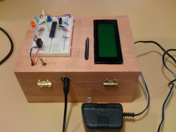
Thanks for the great idea here is my nerdkit box. Here is the top I recessed the LCD display. On the right is the power switch
Just enough room for the componets
I put a power port on the side of the box.
|
|
December 26, 2009 by Rick_S 
|
Very good implementation of a great Idea. Got my creative juices flowing this day after Christmas morning. Using the box to store all the extra bits is a good usage. Is that a different LCD or did you remove and replace the female header socket so that it was perpendicular to the board? I just may have to pay our local craft store a visit to see what kind of small wooden boxes they carry. Great job both of you!! Rick |
|
December 26, 2009 by magiwells |
I just bent the header socket up. Daniel |
|
December 28, 2009 by hevans (NerdKits Staff) 
|
Hi everybody, These look great! Awesome examples of do-it-yourself ingenuity. Keep up the awesome work! Humberto |
|
December 30, 2009 by mongo 
|
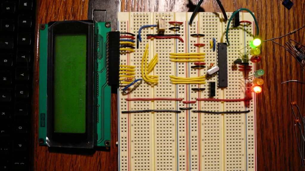
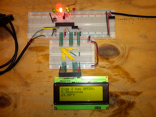
OK, I have the picture uploading figured out now... A couple of upgrades made to the basic kit for me! Pictured is the traffic light circuit in operation. I had a couple of larger breadboards kicking around so I decided to use them. The little one is still part of it but didn't fit in the pic. I also added the contrast pot to the LCD display. (It actually did make the display a little cleared). The bigger area gives me more room to add different things without getting cramped for space. The power supply is actually a commercial Sola SDPS-5-100 5V/5A power supply. I recently bought a couple more processors and displays and will be assembling kits similar to the others shown in earlier messages. Thanks for the idea guys! I think I will put together a cable to make the display a little more flexible in the near future.
|
|
December 31, 2009 by Rick_S
|
mongo Very neat wiring, I love the idea of the second breadboard to clean up the LCD connection. I always try to make my breadboards neat like that but somehow it never ends up that way!! |
|
December 31, 2009 by mongo
|
I didn't include the programming stuff but I made it into a small 4 lead plug that connects just off the corner of the processor where you can see the little jumpers installed. |
|
January 03, 2010 by DrNoExpert |
Using a breadboard i had since i started electronics, a few terminal blocks and fuse holder my dad had, a Motorola 5v, 550ma battery charger for a power supply, I made a really convenient, easy to repair and move nerdkit mount. Http://home.comcast.net/~Alex.noble/kdk_0979.JPG |
|
January 03, 2010 by Rick_S
|
That looks rugged!! Pretty heavy duty terminal block. You definitely won't have to worry about wires pulling out between items. Looks good. Rick |
|
January 03, 2010 by mongo
|
YIKES!!! A little on the overkill there for my taste... Looks like there is someone else with access to industrial parts. My biggest problem is finding screws small enough to fit the holes in the display board. In my industry, the smallest parts are 1/4-20's... (Petrochemical) |
|
January 13, 2010 by DrNoExpert |
my dad had some terminal blocks, helps me to be able to take the kit around more easy without the risk of wires coming out of the lcd and breadboard, yet you can make some makeshift terminal blocks by:
makeshift and cheaper terminal blocks. don't have any pics of the solution, yet you can get the idea.It is a nice way to keep wires organized to make the kit better. |
|
January 13, 2010 by BobaMosfet 
|
mongo, very, very nicely organized.... I like that. Such habits will serve you well. Now, can someone help my poor tired mind understand how to make pics viewable so I can contribute in imagery what I cannot do so well in sheer verbocity? Please.... BM |
|
January 14, 2010 by Rick_S
|
Just store the pic in a free online account like photobucket. Then use the markup shown below (don't forget the ![] before your link in parenthesis. Place the url for your pic in the parenthesis. I don't think you have to type the "alt image text" in the brackets but you do need the ![]. Rick |
|
January 14, 2010 by mongo
|
Boba, It took me a bit to figure out the photo uploads... I just put up a PhotoBucket.com account and copied/pasted the link into the text. A little tricky but I got it now. The first attempt was through my website but the pictures are HUGE in file size. photobucket resizes them to make them transfer faster. (plus, my upload speed is not very fast on my server) |
|
January 15, 2010 by Mike |
Note the wiring errors on the high number side of the chip. All fixed now. Everything, but the lm34 worked until I actually read the temp. It siad it was right at 500 F. I figured that was probably wrong.
|
|
January 25, 2010 by Phrank916 |
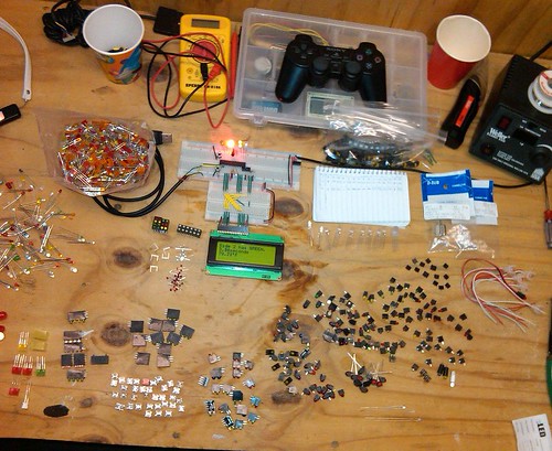
My Nerdkit got an upgrade this weekend. Thanks to mongo for the LCD re-wire idea, and to Rick_S for the reset button idea. All I've added is a larger breadboard that cost $5.99US and two momentary on buttons ($0.35US), one is to reset the MCU and the other is for the traffic light project which you can see running in the pic: I've also been trying to organize my bag o' random LEDS today:
Ted |
|
January 30, 2010 by mongo
|
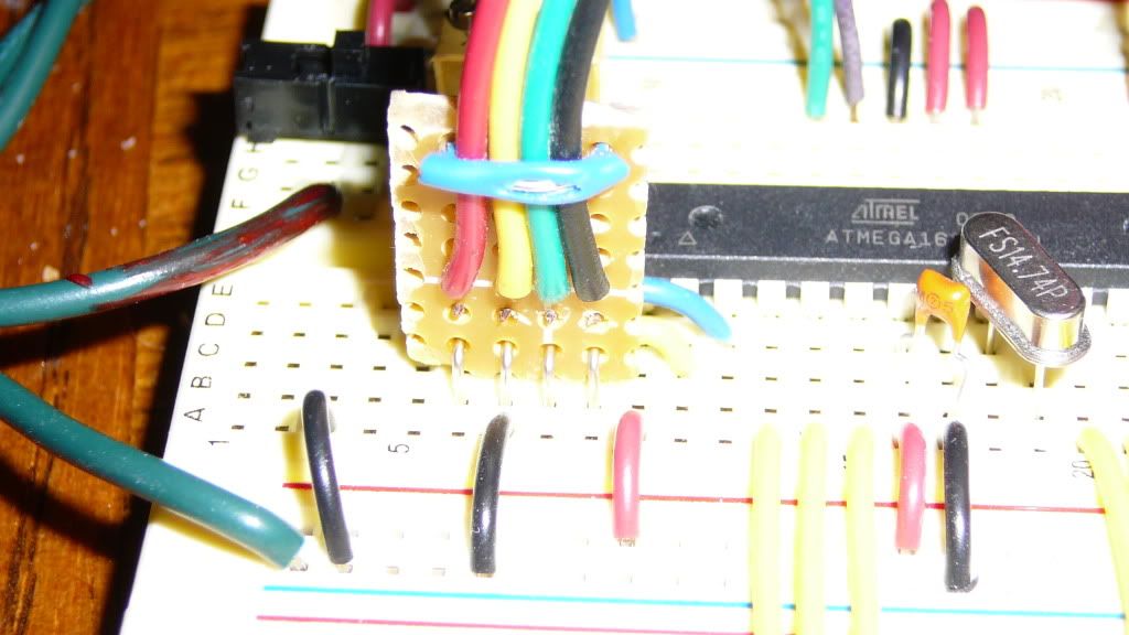
A simple connector for cables... Perf board and a little bit of wire. Note, I have the yellow wire on the ground pin... Not using the original interface and it has a little different pinout. Also not using the +5 pin as the new interface is powered by the USP port. I think this is the way the new interface in the kits also work but I have the older one.I used the same wiring harness, just have to remember which interface I am using. The blue wire across the top is just to keep things in place so the split in the insulation is no problem. |
|
February 02, 2010 by RayMarron |
I got the exact same box as David from Michael's. I mounted the battery under the lid w/ adhesive velcro. The USB cable comes up through the lid, too - curls up nicely inside when not in use, and I drilled a hole right at the seam of the lid so it sits flush when in use. I thumbtacked a chain from an unused piece of jewelry inside to keep the lid from opening all the way and bending the stuff on the breadboard. I had almost as much fun making the box as I did the projects! |
Please log in to post a reply.
|
Did you know that you can read diagnostic data from some cars with a NerdKit? Learn more...
|


Copyright © 2013 by NerdKits, L.L.C.

