Interrupts: Interfacing a Microcontroller with a PS/2 Keyboard

A very important step when moving from basic microcontroller programming to advanced microcontroller programming is the introduction of interrupts into your code. Interrupts are pieces of code, much like functions, that are executed when outside events occur. Interrupts can be used to react to all sorts of outside inputs including pin changes driven by outside devices. With the use of interrupts, you give your code the ability to react to events as they happen (interrupting your other code), instead of waiting for your code to get to a place where it can handle an event (which is known as "polling"). It is a programing idea that can take some getting used to, but the power it gives you in an embedded system is well worth the effort.
This project uses interrupts to interface a PS/2 keyboard with the USB NerdKit. The simplicity of the protocol and the asynchronous nature of the clock generated by the keyboard make this a great simple start for getting familiar with interrupts and interrupt handlers.
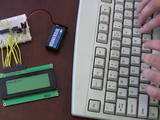
Keyboard Project Phyiscal Setup
For the actual PS/2 keyboard side of this project, we chose to sacrifice an old PS/2 keyboard. Luckily, since modern keyboards are almost all USB keyboards, PS/2 keyboards are quite cheap and easy to come by. If you do not want to chop your PS/2 keyboard, you can always get an extension cable for a PS/2 keyboard and then cut the end off that. (You can also find cheap PS/2 keyboards online.)
The first step is to figure out which wire is which. The male side (keyboard side) of the PS/2 interface has a standard connector with pinout shown below:

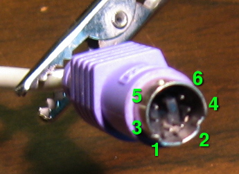
| Pin 1 | Data |
| Pin 2 | Not Connected |
| Pin 3 | GND |
| Pin 4 | Vcc (+5V) |
| Pin 5 | Clock |
| Pin 6 | Not Connected |
Hopefully, once you chop off the connector, you will see that there are 4 colored wires in the keyboard cable. Now you need to figure out which wire is which. You can do this using a multimeter, and checking the resistance from a given pin on the connector to the cutoff end of the wire. Once you know which wire is which, it is a good idea to mark it, or at least write it down somewhere.
In our implementation, we use ATmega168 pin PC2 as the data line, and PC4 for the clock line. Vcc and GND should be connected to the rails accordingly.
PS/2 Keyboard Protocol
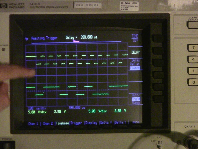
As stated in the video, the PS/2 Interface is quite easy to implement. To send a key stroke, the keyboard begins driving the clock line. On the falling edge of the clock line, the data line represents the current bit. Each keystroke is sent as 11 bits: first a start bit of 0, then the 8 bits of the scan code (least significant bit first), then a parity bit (odd parity, which we did not implement for simplicity's sake), and finally a stop bit (always 1).
Scan Codes
As is the unfortunate case with standards and protocols there are usually more than one different version of it. Most PS/2 keyboards you find default to Scan Code Set 2. Even though most of the common characters are represented with a single 8 bit scan code, some of the keys are "extended" keys whose scan code is more than 8 bits. In that case, the keyboard just sends two sets of 11 bit frames.
In addition to letting you know when a key was pressed, the keyboard also sends a break code when a key is released. The break code for most characters happens to be 0xF0 followed by the code for the key. Our simple implementation ignores realease keys for the most part, except in the case of the Shift key. It does keep track of when the shift key is pressed, and when it is released. It is up to the main code, not the interrupt, to adjust the displayed characters accordingly.
Our code uses an array to store the relationship between scan codes and the character pressed. We use the scan code to index into an array of characters that holds the correct character at a given position. For example, the 'a' key has a scan code 0x1C (this is a way of saying 1C in hexadecimal, which is 28 in decimal or 00011100 in binary). Our mapping array holds the character a, in the 0x1Cth position. This way, to render a scan code into a character we merely need to do a constant time lookup into the array with the scan code.
The PS/2 protocol can actually do two-way communication -- that is to say you can actually send information to the keyboard. This can be used to set the LED lights on the keyboard (can anybody say dancing lights routine?). You can also adjust certain parameters on the keyboard including the delay between repeating keys, and the rate at which the keyboard sends repeating keys. There is a fantastic writeup that covers the complete PS/2 Keyboard Interface by Adam Chapweske.
Other Interrupt Examples
Here are a few of our other videos that use interrupts. As you can see, they are very common when doing complicated tasks:
Setting Up an Interrupt
Setting up an interrupt, is mostly just a matter of finding the right registers in the datasheet. Page 16 on the ATmega168 datasheet has a short intruduction into how interrupts work on the chip. More detailed information about interrupts can be found starting on page 57.
Once an interrupt is enabled, you need to define an interrupt handler for that particular interrupt vector. This is done using the ISR() notation:
  ISR(interrupt_vector){
    //interrupt handler code
  }
Finally, you need to turn on the global interrupt enable flag of the microcontroller with a sei(); function call. After this point, the microcontroller will be allowed to jump to any interupts handlers as needed. (This can be disabled with a cli(); call, which is sometimes important for preventing interrupts from firing during critical code sections.)
A complete list of the interrupt vectors available on your chip can be found in the avr-libc documantation.
Interrupts - Things to Watch Out For
As we mentioned in the video, when dealing with interrupts there are a few things you need to be aware of:
Volatile
If you take a look at the code for this project you will notice that some of the variables have the keyword volatile. This is necessary for global variables that can be set by an interrupt handler, and then read by either the main code or a different interrupt handler. This keyword tells the compiler to not make any assumptions about when, or how the variable can change.
Interrupt Timing
Whenever dealing with interrupts you need to think about how long your interrupt will take to run. For example, in this project the keyboard sends data at somewhere around 10Khz. So there is 1/10,000th of a second between consecutive falling edges of the clock. Your interrupt hanlder needs to run faster than that so you do not miss the next interrupt. We are not saying it is not ok to have long interrupt handlers that do a lot of processing, but you just need to be aware of how long you have to do your processing, and what the effect of missing other interrupts will be. Whenever possible, it's usually best to keep your interrupt handlers short and to the point.
Specifically, you should know that if you have for example a timer interrupt and a pin change interrupt, if the timer interrupt handler is running, the pin change will still be noticed and this will set a flag. As soon as the timer interupt handler code returns, the microcontroller will see that this flag is set and jump to the pin change interrupt handler code. So this generally does what you want (although not necessarily at exactly the right time), but you have to note that only one flag can be stored for each type of interrupt, and if there are two pin changes while the timer handler code is running, the pin change handler will still only fire once.
Source Code
You can download the source code here. The zip file includes the C file, as well as the font file and python code used to generate the character array.
More Videos and Projects!
Take a look at more videos and microcontroller projects!
Comments
|
Did you know that you can use a transistor to interface between different voltage levels of digital logic? Learn more...
|


Copyright © 2013 by NerdKits, L.L.C.