OBD II Car Computer

Using the OBD-II (On Board Diagnostics) protocol, we can read live information from a car's computer with our NerdKits microcontroller kit, as explained by our guest star, Elena T., MIT class of 2011. This uses the port under your steering wheel to receive all kinds of information, and is used by auto mechanics for troubleshooting the "Check Engine" light, and for periodic emissions tests with onboard sensors.
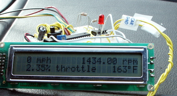
In this microcontroller project, we implement the Variable Pulse Width (VPW) protocol, which is generally found on General Motors cars. Please note that if you attempt this project, your car may have a different signaling protocol, which would not be compatible with our code. The car we used was a 1997 Chevy Cavalier. This was introduced soon after the 1996 law requiring US cars to have OBD-II buses, but there are not many sensors accessible from the data bus. On newer cars, you'd find oxygen sensors (allowing you to calculate MPG), but for our demo, we were able to measure:
We realize it's a bit hard to see in the video, so here's a still photo:
WARNING: Please note that by attempting this project, there are several risks to yourself and your property. This project involves working in the presence of car battery voltage, which can supply dangerous amounts of current and cause fire or electrical damage. This project involves working with your car computer, and while manufacturers do their best to make them robust, it is possible to irreversibly damage your car's computer or the vehicle itself. And of course, if you're the driver, you should be focusing on the road, and not some circuit and LCD on your dashboard.
Schematic
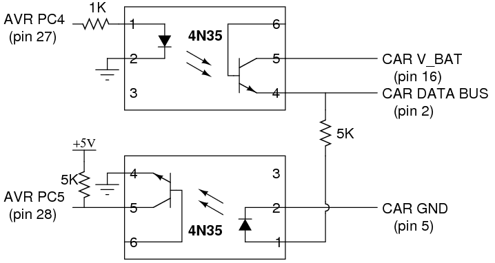
Optocouplers (or opto-isolators) provide a way to transmit information without creating a direct electrical connection. In a single small chip package, they have an LED and phototransistor. Current passed through the LED side of the chip makes light, which hits the base of the phototransistor and allows current to flow through the collector to emitter. This may seem unnessary, but it is useful for a few reasons:
However, we found that it was fine to draw power directly from the car to power the NerdKit. To do this, we connected the car ground to our circuit ground, and the car battery voltage to the input of the voltage regulator. We also added an extra large bypass capacitor (4.7uF) to smooth the ripple on this supply and guarantee proper operation.
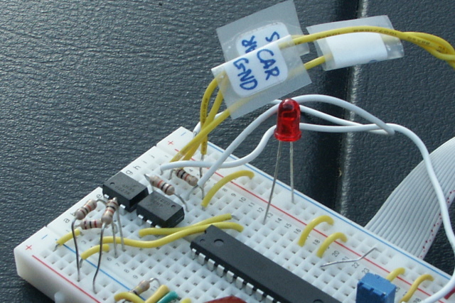
Here's a photo of the circuit on the breadboard. The three tagged yellow wires go to the car's OBD-II port.
Parts List
| Photo | Part | Quantity | Description |
|---|---|---|---|
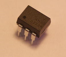 |
Optocoupler, 4N35 | 2 | One optocoupler is used for each direction of data flow. |
You'll also need a few resistors to implement the schematic as drawn above. We used one 1K, and four 10K (two in parallel to make each 5K).
Source Code
You can download the source code here. Please note that the VPW protocol is a particularly "messy" one to implement, and that much of the source code here would not be applicable to a project with a different signaling protocol. This is a fairly advanced example of microcontroller programming.
Acknowledgements
The crc8buf checksum routine used was from Bruce Lightner's excellent article on the OBD-II protocol. (Circuit Cellar, Issue 183, October 2005; [code])
The paper on the VPW (J1850) protocol by D. John Olver at Intel Corporation was also very informative and useful toward implementing the standard.
More Videos and Projects!
Take a look at more videos and microcontroller projects!
Comments
|
Did you know that interrupts can be used to trigger pieces of code when events happen? Learn more...
|


Copyright © 2013 by NerdKits, L.L.C.