NEW: Learning electronics? Ask your questions on the new Electronics Questions & Answers site hosted by CircuitLab.
Basic Electronics » Strange behaviour with a DC motor
|
August 02, 2010 by CyberGod |
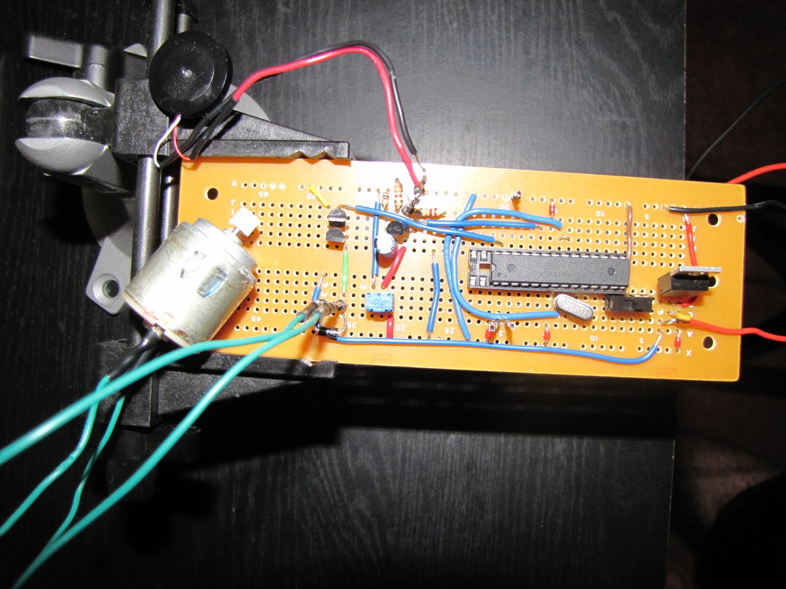
Hi, I am having a vary strange issue that I am unable to solve. I combined the Piezoelectric Sound Meter with the USB Servo-Guided Water Squirter projects to create a device that activates a DC motor after reaching a certain sound level. It all works well until I connect the actual motor. Once the motor is connected things get strange. The motor runs for about a second and then stops, and the rest of the code is not executed. It does that every time the sound threshold is reached. When I measure the voltage when the motor is not connected it reads 12V for when the motor should be on and stays on for the correct amount of time, and 0V for when it should be off. I also see the debugging messages on the serial port, but with the motor connected it reads about 4V for about one second, and I only see part of the messages on the serial port. I've used all the parts from the two corresponding projects, the simple amplifier for the sound meter and the two 2N7000 in series for the motor. Again, it works perfectly with the motor not being connected, it only misbehaves with the motor connected. Here's a picture of the whole thing:
Here's the code: All suggestions highly appreciated! |
|---|---|
|
August 02, 2010 by mrobbins (NerdKits Staff) 
|
Hi CyberGod, What kind of power supply are you using? It sounds to me like the motor might be drawing so much current while starting that your power supply is unable to handle it, causing a voltage drop. If the supply voltage (input to the 7805) drops low enough, it will cause the microcontroller to reset, which you would see as failing to run the rest of the sound-trigger code. Instead of the DC motor, can you try connecting an LED in series with a 1K resistor? (This means that even with a 12V supply, you'd use maybe 10mA for the LED.) See if the LED lights at the right times and if the rest of the code executes. This will tell you about whether the circuit is working with a relatively tiny load. I think that you have already confirmed this based on your multimeter voltage readings. One possible "band-aid" here is to add some extra bypass capacitance. For example, add another 0.1uF capacitor directly parallel to the motor. This helps with noise / current and voltage spikes due to the brushes of the motor. Also, add a large bypass capacitor at the output of the 7805, for example a 10uF capacitor in parallel with the +5/GND rails. These two additional capacitors might be enough to keep the digital part of your circuit alive during any motor transients. However, given your description of the problem (motor works for ~1 second), the time constant is so long that I actually am not too hopeful that these small capacitors will make a difference. (Even the "large" 10uF capacitor will only supply 10mA for 1ms before dropping by 1V.) Another possible workaround is to use PWM to more "gently" start the motor. Instead of just turning on the motor 100% for 6 seconds, you could use pulse width modulation to turn it part of the way on, which would reduce the current consumption (but also the speed of the motor). If you accelerate the motor more gently, you will reduce the peak current consumption significantly. This will require some fiddling with PWM to see at what level you beat the static friction, etc. But you may find that you can turn the motor on 30% for 1 second, then 50% for 1 second, then 75% for 1 second... Hope that helps! Mike |
|
August 03, 2010 by CyberGod |
My power supply is 3-12V/600 mA. I did the test with the LED and the resistor and it works as expected. I'll try the two capacitors workaround and I will post the result. I have one 1000uF capacitor, can I use that one in parallel with the motor ? Can I use different power supply that provides bigger amperage? I wonder how you guys made it work in the Servo-Guided Water Squirter project. |
|
August 03, 2010 by hevans (NerdKits Staff) 
|
Hi CyberGod, Did the motor you got have any sort of information about it as to how much current it draws? When you say 3-12V do you mean it is an adjustable power supply. If so what you running it at, and is it a voltage that that is right for your motor? Have you tried measuring the voltage at your power rails with a multimeter as the motor starts running? Humberto |
|
August 04, 2010 by CyberGod |
The motor that I got comes with the water pump that you use in your USB Servo-Guided Water Squirter project and it doesn't really have any text on it besides "Mabuchi Motor". After searching the web for the same brand similar looking motor I found this one that looks close enough: http://www3.towerhobbies.com/cgi-bin/wti0001p?&I=LXSR93&P=FR. It looks like it draws 270mA with no load. I use the 12V setting on the power adapter and when I connect just the motor to it it spins very fast and starts instantly. When I connect the motor and reach the sound threshold the voltage on the power rails drops from 12V to 8V for a second, the motor spins, then stops and the voltage goes back to 12V. |
|
August 04, 2010 by mongo 
|
From what I just read, it sounds like you fried the motor. The one listed in the link has a voltage rating max at 3V. 12V might have damaged it. A sign like voltage going back up after the motor stops is not a good one. The voltage drop on the supply is evidence that the motor also loaded it down too much. I would suggest driving a relay through a FET or other transistor. Use the relay to power the motor. Make sure the motor is rated for the power supply in use. |
|
August 04, 2010 by CyberGod |
The motor is for 3-6V I've just confirmed that with the reseller. I am not sure if it's damaged because it still works when I power it directly from the power supply. I also added a 10uF capacitor in parallel with the motor and this makes it run longer but still resets the MCU. Can you draw a diagram of how can I use a relay and the FET plaese, this will be of great help as I am still pretty new. One more thing, can you tell me if connecting a 1000uF cap in parallel with the output of the 7805 can damage the MCU because I just did that and I am pretty sure I fried the controller. At least I am learning through doing, and I got bunch of MCU's to fry. Thanks for all your help I am learning a lot. |
|
August 04, 2010 by mongo
|
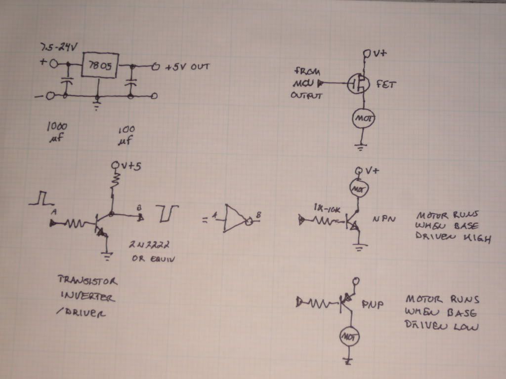
OK, here are a few simple sketches to get you started.
To operate the motor, use the unregulated side of the regulator but make sure it is within the limits. The 7805 circuit shows where a 1000 uF cap should go. You can add a 100 uF cap to the output to limit the little bit of noise the MCU can generate. Adding a 100 uF cap across the servos can also help limit the noise they cause in the power supply. The FET is the same as the ones supplied in the kits. the NPN transistor is a general purpose 2N222 or 2N3904. The PNP is a 2N3906. Resistors are needed to limit the loading on the MCU outputs and are not needed on the FET. The NPN inverter is a typical TTL driver/inverter. The output resistor should be around 330 ohms. You can see how it is similar to the motor driver circuit. |
|
August 05, 2010 by CyberGod |
Thanks Mongo, Can you elaborate more on "I would suggest driving a relay through a FET or other transistor." Thanks |
|
August 07, 2010 by BobaMosfet 
|
CyberGod.... what Ohm value do you get when you disconnect the motor and put a Ohmmeter across it, please? BM |
|
August 07, 2010 by mongo
|
To drive a relay, just substitute the motor with it. Add a diode across the relay to reduce the inductive kick back across the relay coil. Put it in reversed bias so it does not act to short out the drive voltage. (you can also do that across the motor as well.) It would appear to have the arrow pointing up in the sketches, right in parallel with the loads. FETs are transistors. The biggest difference is the input impedance and gain. The normally do not need a current limiting resistor at the gate as you might need on a standard transistor would on the base. FET means Field Effect Transistor. The gate is actually isolated from the other two terminals and the transistor senses the electrostatic field when it is present. |
|
August 07, 2010 by mongo
|
Oh... Driving through a transistor just means connecting the base or gate to the output of the MCU instead of the motor or relay load. Let the transistor handle the load instead of the MCU output. |
|
August 09, 2010 by CyberGod |
BobaMosfet, I've tried two similar motors with the same result, on one I get 3.3 Ohm and on the other 13.8 Ohm. Both of them spin briefly and cause the MCU to restart. I think this will remain a mystery to me. Not sure how the nerdkit guys did it in their project without any relays and extra capacitors. And mongo, thank you for the information it was very educational. |
|
August 09, 2010 by mongo
|
If it is causing the MCU to restart, it is either dragging down the power supply or it is generating a lot of noise on the power and confusing the system. |
|
August 10, 2010 by hevans (NerdKits Staff)
|
Hi CyberGod, We didn't use relays in the pump video, but we almost certainly did add extra capacitors on the power rails to help stabilize the voltage from the 7805. They were not huge capacitors, but probably the same 10uF capacitor Mike mentioned in a post above that you try using. Humberto |
|
August 11, 2010 by BobaMosfet
|
CyberGod- I suspect the motor returning a 3.3 Ohm rating is bad-- has been damaged. That resistance is too low, and will result in greater current demand than your supply is rated for. The motor returning a 13.8 Ohm rating is a load at approximately .437mA. If you operate it at 12VDC (twice it's rating) it will consume over .800mA and eventually burn up. You can see that you are at or exceeding what your supply can deliver current-wise- this would appear to be your problem. I suggest running the motors at their minimum voltage and using a current-limiting resistor of the appropriate power-rating. BM |
|
August 19, 2010 by hapshetsut |
i would personally vote for the relay option as the simplest quick fix, but an additional potential solution that comes to my mind is that radio shack often sells matched IR emitter-receiver pairs, which make excellent isolation switches when optically coupled (i wrap the leads in electrical tape, and then put a layer of aluminum foil round the taped part to block some of the ambient IR). Forrest Mims' pamphlet on 'Communications Projects' has some good information on this kind of thing, too. As an additional note, if the motor works, but that 3.3 Ohm measurement is duplicable, i’d think a mid range resistor in series with the motor might help mitigate some of the current draw, which may or may not help, but it might prevent further damage to the motor. |
|
November 10, 2011 by jfbrink |
Hi, all, I realize that this is a rather old thread, but I have found it useful today and wanted to add some comments based on my own experience, and share what elements of the advice given above solved the problem I was having, which had the same symptoms as the original poster. My comments are based on PWM speed control as presented in the Motors 101 code. -Matching motor voltage rating to input voltage is crucial. This advice seems obvious, but I didn't follow it at first and I was confused by the inconsistent results until I smelled the motor. So, getting the right motor / power supply combo was step one. -Step two was adding a 0.1uF capacitor in parallel with the power/ground leads to the motor, per Mike's suggestion above. With this addition and pulling un-regulated power, I was almost home free. -Step three was a realization that my motor didn't want to start at a PWM below 200ish. Since the Motors 101 code starts PWM at 150, the motor only started if I either gave the shaft a twist or heated up the temperature sensor. So, I increased PWM_START to 256. With that, I have a consistently smooth-running, PWM responsive motor that does not reset the MCU. A couple more observations: -In the Servo Squirter tutorial, they put two 2N7000s in parallel. For me, this resulted in a very choppy rotation. I removed one of the 2N7000s and the results were smooth. -Above, Mike suggests adding a 10uF capacitor in parallel to the +5/GND rails. This didn't hurt, in my application, but neither did it help. It is really the 0.1uF cap at the motor that cleared everything up. Without that, the motor does not go. Thanks to everyone for your help. Without this forum, I would be banging my head against the wall. Jesse. |
Please log in to post a reply.
|
Did you know that you can impress a loved one with a digitally-controlled Valentine's Day Card with randomly twinkling LEDs? Learn more...
|


Copyright © 2013 by NerdKits, L.L.C.