NEW: Learning electronics? Ask your questions on the new Electronics Questions & Answers site hosted by CircuitLab.
Everything Else » PCB prototyping
|
March 29, 2010 by treymd |
I'm curious as to what process everyone is using to make your projects. I plan (and am obtaining) the chemicals to do negative film resist PCBs. But the supplier I found a.) is on the other coast, and b.) only sells little bottles of the stuff and I'd like to order in larger quantities some day. It's tricky tracking down the actual chemicals used in the process. |
|---|---|
|
March 29, 2010 by Rick_S 
|
I use the laser printer method and etch with a Hydrogen peroxide / Muratic acid mixture. Works good for me. Rick |
|
March 29, 2010 by mongo 
|
I guess I am old-school... I draw out the circuit to scale, glue it to the board and spray lacquer on it to seal it up. Then painstakingly cut out where the traces AREN'T. When done, I use ferric chloride as the etching solution and slosh it back and forth in a baking dish. Takes FOR EVER!!! I have also used silk screening techniques, positive and negative photo-etching and the good old dremmel tool too. |
|
March 29, 2010 by Rick_S
|
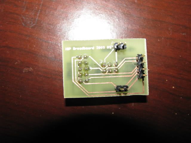
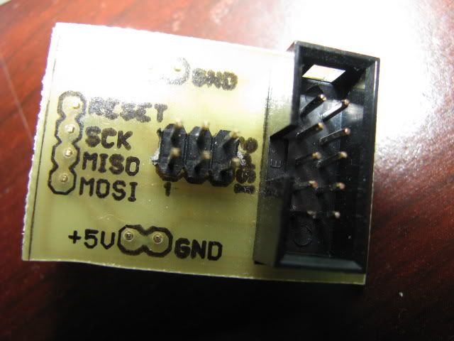
In case you are wondering what you can get with the Laser printer method, here are a couple of pics of boards I've made.
You can even use the laser transfer method to "Silk-screen' the top. Rick |
|
March 29, 2010 by treymd |
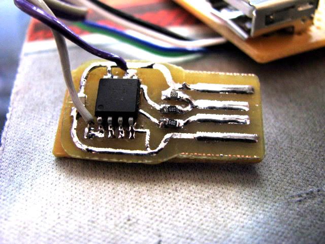
Nice! is that a usb to serial ttl converter in the 3rd pic? |
|
March 29, 2010 by treymd |
Mongo you used a dremel to etch? how? I have one sitting right here... I'm thinking CNC machine and plain old copper clad board! |
|
March 29, 2010 by mongo
|
The Dremel method is very difficult. I haven't had to use it for years but I sure have some memories. Yep, it works but it's best to keep it to the very simple things. I even built a tiny drill press for the flex shaft Foredom grinder. (The actual brand). The spindle is easier than the ones with the motor in the whole unit, though I have one of those too. I use it in that configuration when drilling the holes in the PCB. That was back when I was making microwave antennas for MDS receivers. |
|
March 30, 2010 by Rick_S
|
No, that's an april fools day joke for my co-worker. It's called a capslocker and will randomly toggle the caps lock key on a computer. |
|
March 30, 2010 by treymd |
Oh, LOL you suck! nothing worst than that random jackass that CAPS EVERYTHING HE SAYS. |
|
March 30, 2010 by treymd |
OK mongo, my wife works with a guy who is really arrogant and needs one of those, could you provide some details? |
|
March 30, 2010 by Starwarslegokid |
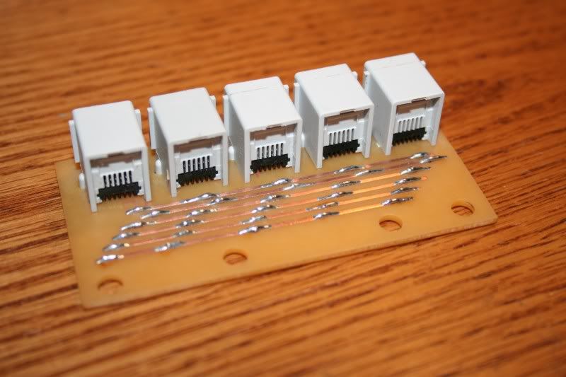
Hi treymd, I etched a few boards using the acid and a copper board, they didn't turn out too bad. Its definitely nice when you have little things and want them done in a weekend and cant wait 4 to 6 weeks for them fabricated. I have two tips for when you do the boards. When etching a copper board, clean the board before you start lol. The copper tarnishes really easy and it prevents the acid from eating the copper away. I would get a piece of steel wool and polish the copper before drawing your circuit up. One neat thing is you can draw the circuit with a simple sharpy and then etch the board, it takes little residue or fingerprits to mess up an etch from my experience. My acid may have been weak by etching standards. Another suggestion, don't leave the board in the acid to long, it will start to eat away at the edges of the etch and then the copper traces break off easy when soldering or unsoldering if you make a mistake. Try and leave the wires as big as you can just incase. Here was the project, i made an I2C expander for my lego NXT, all the jacks are wired in parallel and use both sides of the pcb
If your making a board that you want really nice and professional and have the time to wait for it, I suggest cading one out and getting it fabricated. I discovered Batch PCB and a tutorial on how to design your own board using the Eagle. You can add silkscreen to the top and bottom for no extra cost and i got the board below made for about $11 and took about 4-6 weeks to get to my house. I'm very pleased B-) Eagle Tutorial from Sparkfun:
I never used eagle till that tutorial and its been about a year and here is the board I made, Its my designated prototypying board for when i'm experimenting with code. Its nice to have a board that you know works and lets you get right down to debugging code without troubleshooting hardware. Too many times of forgetting to put the crystal back in my breadboard ;-) lol. Good luck, hope this helps B-) Scott |
|
March 30, 2010 by bretm 
|
How did you do it for that price? I went to the Batch PCB site and it looks like $10 per order plus $2.50 per square inch. |
|
March 30, 2010 by mongo
|
...An arrogant guy needs one of what? A Dremel tool? A Foredom Flex shaft die grinder? An MDS receiver? A miniature drill press? The only thing that might not be common knowledge is the MDS thing. It stands for Microwave Distribution system. It was the method that TV broadcasters used to broadcast programming like HBO and Cinemax without cable TV. You have probably seen the rod antennae on top of various roofs in years gone past that look like a stack of washers spaced out on a rod. That's MDS The receivers I made were parabolic antennas. High gain units for distant reception. I found that PC board material made an excellent setup, complete with active matching and tuning as well as a sub reflector, all etched in the copper.The 1.2GHz range gives a reasonable wavelength to work with and I think the overall active element was around 3-1/2 inches long.(or close to it). I used the die grinder to tune the lengths for optimum performance. |
|
March 30, 2010 by Starwarslegokid |
Hi Bretm, Sorry about that, I need to clarify the price. It was $11 for the square footage cost of the board, and each batch of boards ordered has a $10 handling charge + shipping. I had allot of other types of boards in the order to make the $10 order charge worth while and forgot to mention that. Also the two times I ordered from BatchPCB they doubled my order, so I had twice as many boards as I was expecting! hehehe. Don't know why they did that but I have no complaints, maybe because it was a small order of 15 boards or so :-) Hope this helps Scott B-) |
|
March 30, 2010 by treymd |
Oh sorry, I meant Rick... and the capslocker, but I googled it: http://macetech.com/blog/?q=node/46 |
|
March 30, 2010 by Rick_S
|
The only thing to look out for, is it only works on some pc's the way it's designed. Some pc's aren't tolerant of the 5v on the data lines. Luckily my co-workers is. Otherwise, the addition of some 3.6v zeners to the data lines will make it more compatible. Some people have had luck by simply increasing the value of the 68ohm resistors. Read all the comments on that page - It'll give you some insight into some ideas and issues. |
|
March 30, 2010 by bretm
|
I think you got double the order because someone else's board in the batch came out wrong and they had to re-run the batch. |
|
March 31, 2010 by treymd |
That MDS is that legal? heh. Kinda cool. If I hadn't blown up my brain with all the reading I've been doing (it totally went blank, the brain does need downtime indeed) I would do some research on it, but alas, that must wait. I have promised a piece of software that has been backburnered for too long, and I need a day or 2 of forced non-learning. |
|
March 31, 2010 by mongo
|
Yes, MDS is legal. It's just a different broadcasting media for things like subscription services. I worked for HBO back in the day when only apartment complexes and motels had HBO. The transmitter was on a mountain nearby and all of the antennas were pointed at it. We began installing home units back in 1979 and I was the guy that did the first ones in the area. When cable became the preferred method, they sold the equipment and other services put it to use. For a while, an adult video service used the equipment but that didn't last very long. I did some of the installations for them as well. |
|
April 22, 2010 by Starwarslegokid |
If anyone is interested in the board I posted above, I got around to posting it on my website with the schematic and link if you want to buy one. Good luck designing your boards, I want to hear how they turned out! Scott B-) |
|
December 26, 2010 by Hexorg 
|
Sorry to bump an old topic but I have a few questions about PCB making. I found a few laser-printer tutorials, but I don't have a stable access to a laser printer. Is there anyway to adopt ink-jet printer for a sharpie-drawn pcb fabrication process? If not, does anyone know a good place for a laser printer? They are generally heavy, so I think getting them online would be masochistic to my wallet, and I'm a poor collage student. lol Also, I've spent past 2 days learning KiCAD (from what I heard, it's just like Eagle, except open source) and I did make a PCB for my RGB LED array (used in my tetris project), but the PCB turned out to be 36 square inches... which is like $80! I've spent $45 for 300 RGB LEDs, so that's just too much. Hence the last question, what's a good way to fabricate large PCBs? |
|
December 26, 2010 by Rick_S
|
Watch newegg sometimes they ship for next to nothing or free. Even on bigger items. I use the laser printer method. I use a small samsung and it works great. I picked the printer up on sale at office max for $50. The best way I found to transfer the toner is using the method in the PCB Fab in a box idea ... a cheap ($20) laminator. The combination of heat and consistant pressure worked real well on the last board I did. Prior to that, I tried the iron method with mixed results. As for the paper, I use old mail order catalogs... Look for one that has glossy look to the pages. Try to find one that if a moist (think sweaty palm type moist) touch makes it want to stick to your skin. Often I'l have to fold the catalog paper over a regular sheet so both get pulled through at the same time because often the catalog paper by itself will just crinkle up and jam. You'll have to experiment with whatever you get to find what works best for your setup. I've never done double sided... Alignment would be the biggest issue there. Rick |
|
January 04, 2011 by Steven 
|
You could potentially drill a reference hole (or two) after you got one side transferred. |
|
March 26, 2011 by leedawg |
I also use the laser printer iron on technique with H2O2 and muratic acid. Works great. You might have to iron on the traces more than once if the first time does not come out perfect but once it looks good on the copper in it goes and in about 20 minutes I get out a really great PCB. I use glossy magazine pages as well in my laser printer they pull through no problem on their own I have a konica minolta 2430dl printer. Old but works great for this. |
|
March 28, 2011 by Hexorg
|
Can you do a "stop solder" with toner transfer? As in, if you try to solder on top of the toner, will it prevent solder from attaching the way silkscreen does? |
|
March 28, 2011 by leedawg |
uh I suppose it could but that would require just removing the toner over the pads only which would be very tedious and a pain to do. Its easier to just scrub it all off and just solder away. The Fiberglass in between does not allow solder to stick to it though if that is what your asking. |
|
March 29, 2011 by Rick_S
|
Plus, the toner melts at a pretty low temperature. I've had some missed in my cleaning and it tends to contaminate the solder making it difficult to create a good joint. Like leedawg said though, the fiberglass between pads does a pretty good job of stopping the solder. Rick |
|
March 29, 2011 by SpaceGhost |
I only have an inkjet printer so I've printed my PCB art from my computer, then went to the library and used one of their coin operated laser copiers with a piece of my own inkjet photopaper to put in the machine. I've done this at Staples too. Laser toner apparently doesn't stick all that well to inkjet photopaper, or so I read someplace. I recall glossy inkjet paper as being recommended, and that is what I've used. It takes a lot of ironing but it has worked very good for me (after some initial trial and error learning process). Text even comes out looking good. Also, it seems that a lot of soaking in water after the ironing really helps the process... Soak it good, then don't be afraid to gently rub off all paper residue (especially on and around text, and traces close to other traces). One thing that I've had mess me up was tape. I've learned that once I've got the paper to stick to the board with the ironing, get the tape off then continue ironing the heck out of it. Just as an extra precaution I try not to use tape over areas where there's traces or print underneath. But of course that's impossible sometimes. Just my 2 cents, Dave |
|
June 23, 2011 by killercow |
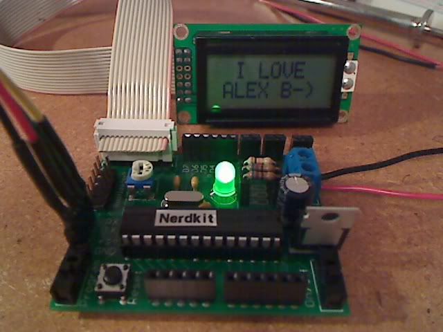
Hi guys! I finally got all my parts in last weekend, albeit, some where kind of big. So, after sorting thru the parts, I was able to build up the test board the Starwarslegokid made. I'll post pictures soon. There are a few things I need to iron out. I think some of my values for the current limiting resistors are a little high, I used 1K ohm for all the colors (RGB). I might mod the board to use 3 small leds vs. the RGB led. I couldn't see any characters on my lcd display....hmmm. The trimmer pot is way to big, I used a 150K. I'm going to see if I can get a 50K trimmer. Once a got the display to work, I was tickled-pink. I going to use an old CD-Rom audio cable for the USB to serial adapter for programming. I forgot how much fun spending hours scratching my head was and then find the problem, fixing it and having something work! When time permits, I'll write up a document with pictures of the build process and and tips that will help make the process easier for anyone else that wants to build one also. I'll also include where I ordered what, there was like 4 sources. I've enjoyed reading thru the forum entries on the various topics. I'm going to make a rocket launcher. I should be posting some code within the next month....work is taking up my free time. Take care all, Kevin Killercow |
|
November 14, 2011 by carlhako |
Rick_S can you please advise how you use the laminator? I did a google search and one site I read suggested modifying the laminator to slow it down. Did you do this? If not how many passes do you put the clad through? Do you do anything special like a extra peice of paper jammed in with the copper clad? I use the iron on method but do not get consistent results. A few times I have not been happy with the results, broken traces and have scrubbed the hell out of the copper clad to remove the toner then redoing. Cheers Carl |
|
November 14, 2011 by Rick_S
|
I haven't done a board in a while, but the last one I did was with my laminator. I used thin copper clad (1/32"). Prior to doing the transfer, I lightly cleaned the copper with scouring powder (Comet) then wiped with 91% isopropyl alcohol with fresh paper towel until nothing came up on the paper towel. I'm not 100% if I fed another piece of paper through with it or not in the laminator, but I don't think so. I do remember folding the paper over the leading edge of the board so the board was pinched between paper as it was pulled through. As for how many times, I don't think I even counted. I just passed it through a few times in all 4 directions then filpped it and did it again. What I mainly remember though was that the end result was the best transfer of toner I had ever had. Not all laminators are the same, keep that in mind. The one I have is a pretty cheap generic one that only cost $20. However, I don't know if all cheap or even more expensive ones will perform the same. You'll have to experiment and see what works. Finally, if you want to get the toner off your copper board without scrubbing like mad, use acetone (or most finger nail polish remover) and it will clean it right off pretty easily. Rick |
|
November 14, 2011 by carlhako |
Hi Rick Thanks for the tip about using acetone. Well before reading your reply I pulled out my laminator and tried to feed it a peice of clad. It made a few funny noises but it came out the other end ok. I prepared my copper clad in a bowl of strong dishwashing liquid and water, with a new scourer and scrubbed it for about a min then dried it with paper towling. I glue a peice of magazine to some a4 paper and feed that into the laser printer which works quite well. Since my boards were long and skinny i could only feed them in one way. I put it through 4 passes then dumped it into a bowl of cold water. Came out perfect almost as good as the original print. Im glad i read this thread I had not heard of using a laminator before. pic: Can see the scratches from scrubbing off the tonor. I dont have any acetone yet.
|
|
November 14, 2011 by Rick_S
|
Looks good, Whatcha making? |
|
November 16, 2011 by carlhako |
I am making boards for my christmas lights. They hold 3 shift registers and have spots to wire on all the leads running to the leds. I am going to redo this one using smd shift registers I bought a stack of them they are cheaper and less holes to drill. With the laminator I can get fine traces no problem. |
|
November 17, 2011 by Rick_S
|
What are you using for your echant and what is your copper thickness. Any special etching tank or are you using a contianer and just moving the board around? |
|
January 24, 2012 by carlhako |
Hey Copper thickness I am not sure, I purchased it a while back, it was the cheapest on ebay shipped from china. I am using ferric chloride poured into a plastic container and use a plastic fork to move it around. I have been havving issues using the laminator with larger boards, even after 10-20 passes traces were still not coming out. I found this article the other day which describes how to mod a cheap laminator readily available from office works here in Australia. http://ultrakeet.com.au/index.php?id=article&name=superFuserV2 cost me $20 for the laminator + $20 for the parts. I have just done my first pcb and am amazed. I will etch it and post a photo in a few days. |
|
January 24, 2012 by Rick_S
|
That laminator mod looks interesting. I may have to tear my laminator apart and see if it's guts are like that. I'm not too hopeful though. I wish there were a source for that laminator in the states as shipping from the other side of the planet makes it a bit expensive. I've been wanting to do some SMD boards but up to this time, have had so so luck. I seem to get a lot of pitting in the traces. The laminator helps for sure but I think my etchant solution (muratic acid/hydrogen peroxide mix) may be hurting my results. I think I'll buy some ferric chloride and see how that goes. Rick |
|
February 18, 2012 by carlhako |
Hi Rick how did you go with the ferric chloride? I have been continuing creating boards and now have it down pat. I have found it takes 2 passes to get a perfect transfer and junkmail works the best for me. Here are some pics. This is the first project where I have designed everything from the ground up, code, eagle, etched and soldered. The copper has some small pits which looks like holes in the trace, its just the lighting.
Here is the board soldered up and to my supprise after flashing the microcontroller (attiny85) worked first go! Little messy I know. After watching some youtube videos on SMD soldering I worked out I am using the wrong tips for my soldering iron. I have a hakko so have some 900M-t-2c type on the way :).
|
|
February 18, 2012 by Rick_S
|
I haven't messed with homemade boards recently... Been playing with other stuff. Your board looks pretty good though. Good job! |
|
February 18, 2012 by mongo
|
SMD soldering is a tough one to tackle. Gotta have a tiny tip on a hotter than normal soldering iron. (the solder wicks away the heat). Not bad... How do the eyes feel after that? ;) A little tinning on the pads also helps. If you do that before you install the components, the solder takes a little quicker and with less heat. Just make sure the tinning isn't little mounds of solder. The flatter, the better. |
|
February 18, 2012 by Rick_S
|
It's not too bad, If you have some good flux, heavily coat the pins with flux, then tac down opposite corners, add some solder and drag a solder bead across the pins. The flux will keep the solder from bridging as long as you don't use too much solder. I just swapped out an smd atmega8 with an atmega328p on a display board I bought from dealextreme. I went from this:
to this:
to this:
using that method. (Added a different crystal and the two smd caps for the crystal too Rick |
|
February 19, 2012 by Ralphxyz 
|
Of course that begs the question WHY? Closer to the current subject of this thread is how did you remove the ATmega8 chip (plus the crystal and two smd caps)? Ralph |
|
February 19, 2012 by Rick_S
|
Why what?? If you are asking why I swapped microcontrollers, it was because I wanted the extra programming space the 328P offers versus the 8 and the original was clocked internally with the external crystal there for time keeping. As to removal, there were no caps on the original setup. The crystal is thru hole, so I heated and pulled each leg to remove it. The mega8 was removed with ChipQuik. That stuff works miracles for removing SMD IC's. I have a lot more details on my blog if you are interested... rs-micro.com Rick |
|
February 19, 2012 by JKITSON 
|
Rick Your blog is super. I purchased 8 of the led boards to use with my TRACTOR PULL SLED MONITOR. Your research will save me many many hours of research on them. Thanks again Jim Kitson |
|
February 19, 2012 by Rick_S
|
No problem... |
|
April 11, 2012 by pcbolt 
|
Rick - While waiting on some components to arrive by mail, I scavenged some parts from an old game controller I found at Goodwill. Had a chance to try out ChipQuik and could not believe how well it works. I got a little carried away and decided to see if I could re-solder a .5mm pitch TQFP back on the board. With a little patience and lot of flux...it wasn't too bad. Not sure if it worked but it looked pretty good. Just wanted to second the opinion of ChipQuick. |
|
April 11, 2012 by Rick_S
|
I first heard about that on this board a couple of years ago when someone stated they used it. I didn't know what it was then and researched it and bought some even though at the time I didn't have a real need for it. Since then though, I've used it a few times always with good success. I'm definitely sold on it and will continue to use it for SMD removal... Unless someday I get a hot air rework station... Even with that though, I would imagine the chipquik would make it easier. Glad it worked out for you! Rick |
|
April 11, 2012 by Ralphxyz
|
I would like to try Chip Quick with my hot air reflow, seems like I might not over heat the component as easily. That sure i a interesting concept, to make a lower melting alloy. It is so simple. $10.00 or so at Amazon. Ralph |
|
April 11, 2012 by dgikuljot |
Hey guys quick question. The copepr clad boards I have ordred from Taiwan are really thick (1.6mm thick copper) Would the hydrogen peroxide and vinegar mixture be too weak to etch away copper that thick? Also I know most of you guys use h202 and hcl or ferric chloride. SO what is the cheapest place to get either hcl or ferric chloride. Thanks, Kuljot |
|
April 11, 2012 by pcbolt
|
Kuljot - I think the cheapest place to get HCl is from a swimming pool supply company. They usually sell the 34% kind. About $6 US for 2 liters. Not sure about FeCl. I think the vinegar solution would be too weak, but H2O2 + HCl would work fine. If you get 34% muriatic acid (HCl) the mix is 2:1 H2O2 to HCl. Sometimes all you can find is 17% HCL and then just drop the ratio to 1:1. |
|
April 12, 2012 by Rick_S
|
The Hydrogen Peroxid/Muratic Acid mix has worked well for me but only for single runs. It won't store after mixed to be used later. I don't have any Ferric Chloride but have considered purchasing it since I know it is a good etchant that you can store and re-use at a later date. I purchased my 34% Muratic Acid from the pool supply section of a local grocery/department store. It's readily available in the USA and is relatively inexpensive. I bought a gallon bottle of it for under $10US a couple of years ago. Rick |
|
April 12, 2012 by dgikuljot |
Thanks for the replies pcbolt and Rick, I will definetly check out the 34 percent Muratic Acid. So does the HCl and H202 just as fast as the Ferric Chloride. I know the Hydrogen Peroxide and Vinegar takes up to an hour, but essentially I will mostly just be etching really small pcb's |
|
April 12, 2012 by Rick_S
|
My experience is that it works quite fast. Just a few minutes. |
|
April 14, 2012 by dgikuljot |
Hey Guys, SO I went to my local Home Depot. They only had 1 Muratic Acid product. It is 2- 1 gallon bottles of Muratic Acid for 10 dollars but the conecntration of the Hydrogen Chloride is 14.5% and that was the only concentration they sell. In your guys opinion will that work, or is it too weak so I can return it without opening it. I am assuming even 14.5 HCL in 1 gallon solution must be pretty strong. Thanks |
Please log in to post a reply.
|
Did you know that NerdKits has been featured in the MIT Undergraduate Research Journal? Learn more...
|


Copyright © 2013 by NerdKits, L.L.C.


 )
)