NEW: Learning electronics? Ask your questions on the new Electronics Questions & Answers site hosted by CircuitLab.
Support Forum » How to get the guide?
|
March 22, 2010 by Hexorg 
|
Is there any way to get the guide for this or that project without buying the project first (maybe buy the guide for $2-$3)? For example the LED Array? |
|---|---|
|
March 22, 2010 by Rick_S 
|
There's tons of info on the forum for the LED Array's. Combine that with the original files from the projects page and you've got pretty much all of that covered. If you have any questions about the LED Array, post them. Many of us have been throught the works on that project and could probably get you through any issues. Rick |
|
March 22, 2010 by Hexorg
|
Ok, well I had a bit different project in mind which basically is the same thing as the "running line" you made. I just found a 100 pieces 4-pin RGB LEDs on ebay, and I was thinking to make them into 10x10 pixels screen. I did a little research and it looks like the best way to drive the screen is by using LED MATRIX, while controlling the component's brightness by PWM (pulse-width modulation). However with this setup one ATmega can control only about 20 RGB LEDs (or 20 pixels), once again, i had 100 of them in mind. My chemistry class is about to start, later I'll try to look up maybe a 128-bit i/o micro-controller (100 bits to control which LED, 3 bits to control which component (R, G, or B), and the rest for future expansion), or maybe there is a pre-made 10x10x3 LED driver. If you have any ideas passing by it would be greatly appreciated. |
|
March 22, 2010 by Rick_S
|
Here's a link to an amazing project using 8X8 RGB matrix. It may give you some ideas for your project. |
|
March 22, 2010 by Rick_S
|
After looking again, they are red/green matrix not RGB. But still an awesome project. |
|
March 22, 2010 by Hexorg
|
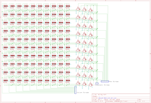
ok, so I thought and thought, and sketched this So, pretty much we have here 3 main groups of wires - row strobe, column strobe, and component strobe. The idea is - by setting one of row strobe and component strobes to ground, and column strobe to +5, I'll be able to light up one LED at a time using only 23 pins. I'd greatly appreciate it if someone would check my transistor's placement. I still get confused which pin does what there. |
|
March 23, 2010 by treymd |
Regarding the guide: If you work out the cost of parts and shipping, the guide is a relatively small part of the kit. You would actually probably pay more buying a similar book. Mike and Humberto have chosen to teach the world rather than horde their great knowledge to themselves, and that to me is worth the small cost of the guide. Not to mention that also present in this forum are people like rick and boba, who have taken their hobby(obsession) to the level that they could answer so many of our questions. You aren't paying for a book, you are paying for help, and it's not even on a monthly basis! The cable company would not do that for you! Support nerdkits, and even after you have learned to load your own bootloader, I've found that nerdkits still is the best source for usb to serial ttl cables. |
Please log in to post a reply.
|
Did you know that you can connect to certain car computers via the OBD-II port with a microcontroller? Learn more...
|


Copyright © 2013 by NerdKits, L.L.C.