NEW: Learning electronics? Ask your questions on the new Electronics Questions & Answers site hosted by CircuitLab.
Project Help and Ideas » Need help with first project
|
December 26, 2009 by stm2000 |
The project is the first one in the nerdkits PDF that allows you to display a message from the company. I can't seem to get it on despite wiring the circuitry the way the book instructed. Can anyone help me. I even have a pic of the wiring. [First Circuit Configuration] (http://i641.photobucket.com/albums/uu139/DHTArtist/Internet%20Requests/100_1739.jpg) [Second Circuit Configuration Battery Leads put into place] (http://i641.photobucket.com/albums/uu139/DHTArtist/Internet%20Requests/100_1739.jpg) |
|---|---|
|
December 26, 2009 by n3ueaEMTP 
|
Maybe I missed them but I didn't see any contrast resistors? That was my problem when I couldn't get my welcome message to display. Chris B. n3ueaEMTP |
|
December 27, 2009 by stm2000 |
I actually solved it. It was the battery connection to the positive rail. I didn't connect it there. I connected it directly to the voltage regulator. I put it in the red rail. |
|
January 06, 2010 by stm2000 |
I am having the same problem again. It's getting power but only the first and third row of the display is showing. I have all the wires connected from the LCD to the processor the way the instructions said. I still can't get the message to show up again. Can anyone help me? |
|
January 06, 2010 by hevans (NerdKits Staff) 
|
Hi stm2000, Could you describe in a little more detail what the problem is you are experiencing. Are you able to reprogram the microncontroller? Do you get characters on the LCD, or just two black lines? Humberto |
|
January 07, 2010 by BobaMosfet 
|
stm- Make sure non of your connections of jiggled loose, or been inadvertently jarred or bumped. Make sure none are crossing (for example, the leg of a resistor touching the leg of another resistor. Have you done anything that would change the code? :P BM |
|
January 07, 2010 by BobaMosfet
|
Check your battery voltage. The 7805 itself drops 2 to 2.5 volts across itself to operate, so requires an input voltage of atleast 7.2V. BM |
|
January 08, 2010 by stm2000 |
I get power, it is just two lines on the LCD showing. One on the first line and the other on the second line. I am checking the data connections. Everything seems to be tight. |
|
January 08, 2010 by stm2000 |
I get power, it is just two lines on the LCD showing. One on the first line and the other on the second line. I am checking the data connections. Everything seems to be tight. |
|
January 08, 2010 by stm2000 |
I have one possiblity. That is the processor may be blown out. This is probably remote but all my connections check and the battery has power. |
|
January 09, 2010 by mrobbins (NerdKits Staff) 
|
Hi stm2000, Have you verified that the mode select switch leaves microcontroller pin #14 unconnected (for "run" mode)? If it's not, and it's unintentionally connecting pin #14 to ground, then you'll be in programming mode, and the LCD will have no data and light up rows 1 and 3 as you describe. Are you still able to program the microcontroller? Do you have something loaded onto it (like the "initialload" program)? Were you able to successfully program it at any point? Mike |
|
January 09, 2010 by stm2000 |
This is actually the first project. The one that displays the greeting from Nerdkits. I am trying to get that to work. I have everything wired as it should. It's just not getting data from the processor. |
|
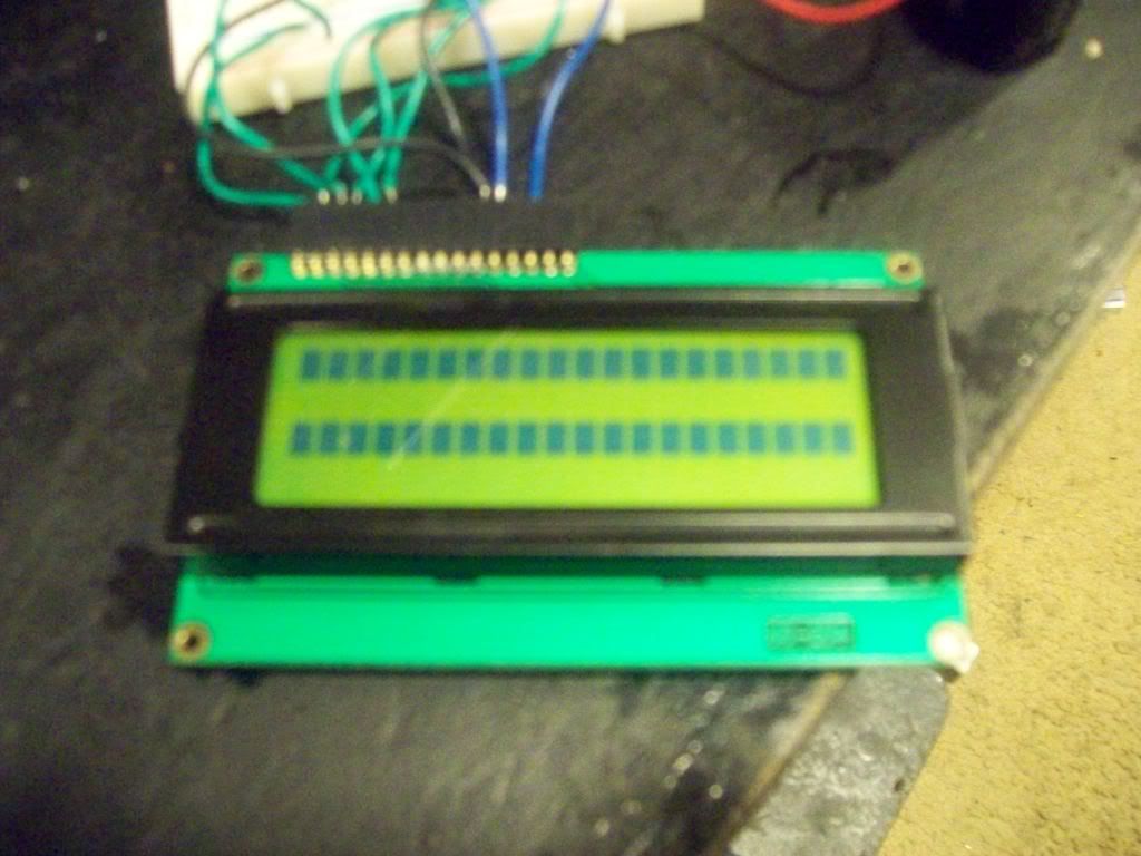
January 10, 2010 by BobaMosfet
|
Can you post a picture of the display, please? Do you have a multimeter-- if so, what voltage are you reading coming off of your 7805 regulator? |
|
January 10, 2010 by stm2000 |
[cpu connections] (http://i641.photobucket.com/albums/uu139/DHTArtist/101_0051.jpg) [wire connections] (http://i641.photobucket.com/albums/uu139/DHTArtist/101_0053.jpg) The multimeter test on the voltage regulator indicated 5 volts even testing the output lead. I also tested the processor and found they were functioning 5 volts. The components are functioning. |
|
January 10, 2010 by JKITSON 
|
HI From the wire connecton photo it looks like you have a wire from the lcd wired to pin 14 on the Atmega 186.. This could hold pin 14 at a low and keep you in programming mode, which is indicated by the lines on rows #1 and #3 on the lcd.. Jim |
|
January 10, 2010 by mrobbins (NerdKits Staff)
|
Hi stm2000, In addition to the other suggestions here, I would also suggest you simply continue along with the guide and try to program the microcontroller. It's possible that we mixed something up on our end and didn't load the "Congratulations" message onto your chip. In any case, please give that a try too and let us know what happens. Mike |
|
January 10, 2010 by mongo 
|
I was able to duplicate the situation, but the only way I could was to turn off power, put in program mode and then turn power back on. I didn't see a programming switch installed yet in the photo but that doesn't necessarily mean that the pin is not grounded somewhere else. (pin 14 of the processor). Re-check pin 14. It's the end closest to the voltage regulator. There might be something there that you can't see. |
|
January 11, 2010 by NK_EK |
Hi, Just to make sure - I cannot see in your pictures if there is a wire going from pin 7 of the MCU to the positive rail. I don't know if having this pin incorrectly wired will result in the condition you're getting, but just make sure. Pin 7 must go to the positive rail (red) and 8 to the negative (blue). Ernest |
|
January 12, 2010 by stm2000 |
I had a theory that the program inside the chip that displays the greeting may have been erased by some erroneous connections. I will proceed with the programming end. |
Please log in to post a reply.
|
Did you know that a flyback diode is important when driving a motor or any inductive load? Learn more...
|


Copyright © 2013 by NerdKits, L.L.C.