NEW: Learning electronics? Ask your questions on the new Electronics Questions & Answers site hosted by CircuitLab.
Support Forum » Piezo Sound Meter help requested with possible wiring error
|
December 23, 2009 by promethean |
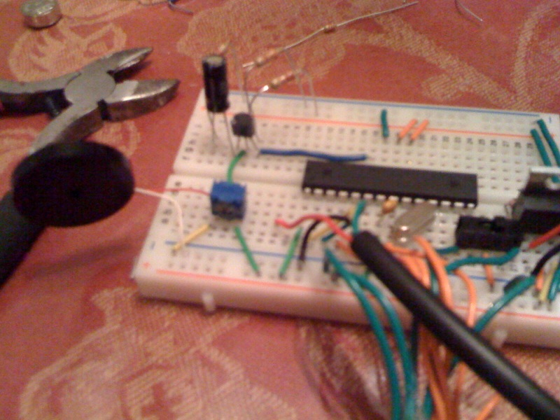
Hey Folks, I'm attaching a photo of my setup. I couldn't figure out exactly where everything should connect from the photos since some of the items are obscured. My LCD display simply reads "Max 1023", "Min 1023", "Dif 0". The potentiometer is set to provide near exactly 0.33V. In case the photo is unclear, here are my connections: Ground -> Left pot pin 5V -> Right pot pin Red piezo lead lead -> left pot pin White piezo lead -> ground Middle pot pin -> middle NJT pin Short cap lead -> 1k res -> ground Long cap lead -> left NJT pin Middle NJT pin -> 3.3k Res -> ground Right NJT pin -> 22k Res -> 5v Right NJT pin -> MCU pin 23 (row 16) Thanks for any help!
|
|---|---|
|
December 24, 2009 by Rick_S 
|
I haven't built this project but based on the schematic, I thing your red piezo lead should go to the center pot pin not the left pot pin. Hope that helps, Rick |
|
December 24, 2009 by promethean |
I gave center pin a shot, no change. A few thoughts have occurred to me-- are there multiple types of 2n3904 of transistors? Maybe I have the wrong kind. This is the exact one I have from Mouser: http://www.mouser.com/Search/ProductDetail.aspx?R=2N3904virtualkey61000000virtualkey610-2N3904 Also, re-reading through the tutorial page, I realized it said that the 0.33v measure shoud be across RE. I don't know what RE is. I had simply adjusted the Pot until it measured 0.33v from the center Pot pin and ground. That may be part of my problem, though probably not all of it, since I've tried very slowly adjusting up and down the range of the Pot. If these weren't the points of the circuit that should measure 0.33v, could you tell me which specific pin/leads I should be obtaining a 0.33v measure from? Otherwise, I've continued to try all sorts of other configurations with different sized resistors, no capacitor, etc., and still no luck. Occasionally I'll get the LCD to show some activity from the circuit, but nothing based on any sound activity from the piezo. I have noticed that when I bridge the two resistors feeding into the transistor I numbers jump around a bit, but that's the only piece of predictable behavior I've been able to obtain. As always, any help/insight is appreciated. |
|
December 24, 2009 by Rick_S
|
Looking at the schematic again on the tutorial page, it appears you have also wired the transistor improperly. The Negative side of the 10uf cap should go straight to ground. The positive side should go to your 1k resistor which goes to the emitter of the transistor (looks like left side in your photo if the flat is facing you). The 3.3K resistor should not be hooked up to the base of the transistor (middle pin), it should be connected to the emmiter (left side). Give that a shot, maybe that'll get it going for you. Rick |
|
December 24, 2009 by promethean |
Yep, that did it! Now I'm just playing around with the pot to see what the gain is like at various levels. I've also noticed that there is much more sensitivity to high pitch than low pitch sounds-- I'm guessing this is due to the cap setup, although I need remove it to test that theory out. Either way, I'd like to see empirically what the effect of the cap is in the output, so out it goes, and in go a few caps of other uF values. In any case, I guess I should have tried to puzzle out the schematics instead of deciphering a low-res photo. But, now that I know the correct wiring configuration, I can look back at the schematics to match things up. Since this time I'll knowing exactly what I'm looking at, it should teach me quite a bit. Thanks for the help! |
|
December 24, 2009 by Rick_S
|
Any Time... |
Please log in to post a reply.
|
Did you know that two resistors can be used to make a voltage divider? Learn more...
|


Copyright © 2013 by NerdKits, L.L.C.