NEW: Learning electronics? Ask your questions on the new Electronics Questions & Answers site hosted by CircuitLab.
Project Help and Ideas » Darkroom timer
|
December 13, 2009 by magiwells |
I would like to build a darkroom timer for my first project. That would turn a 110v light on for a time then shut off. I would like the time to be adjustable (1 sec - 5 min). |
|---|---|
|
December 13, 2009 by FWSquatch |
Sounds like a fun and very do-able project. I don't know much about using that kind of power, I just know you'll need a relay. I also know enough to tell you to be very careful with that kind of power and don't burn down your house! This page has some good info on using a relay to switch on a light bulb. He's using an Arduino, but that doesn't really change the way you wire it up much. I think you can build this with a pushbutton, potentiometer, and a relay. You might want to toss in the LCD, too. On the software side of things, I think it wouldn't be too hard. I had to do some similar coding in my intervalometer project. Basically, when you push the button, you'll want the program to check for a time setting and then flip on the light bulb for the desired amount of time. If you download my source code and dig through it, I think you'll see what I'm talking about. If you want/need more explanation I'd be happy to help you with it. How many different time settings are you looking at? Will you be able to look at the LCD in the darkroom or will everything be totally dark? I think putting the LCD in the project could make it easier to set your timings. |
|
December 13, 2009 by FWSquatch |
Doh! I forgot to explain the potentiometer. I used it in my intervalometer to set my timing intervals. I just took some of the tempsensor code and stuck a pot in the place of the temperature sensor. That might be a way to set your timing as well. |
|
December 13, 2009 by Rick_S 
|
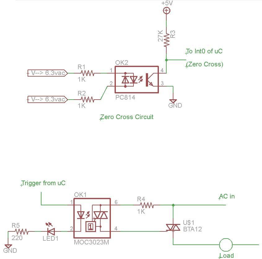
You don't necessarily have to have a relay. Depending on the currant draw of the bulb, you can make a solid state relay from a triac. I did this a while ago while making a dimming circuit driven by a MCU.
The lower portion of this schematic shows how to hook up a basic triac driven by a triac out optoisolator. With this configuration, you can easily turn on an incandescent light bulb as easy as turning on an led with the micro-controller. BE VERY CAREFUL WHEN WORKING WITH LIVE MAINS THEY CAN BE DEADLY!! Sounds like a very good and doable project. You can probably modify the real time tutorial code to generate the timing. Rick |
|
December 13, 2009 by n3ueaEMTP 
|
@magiwells, My Personal House System project does exactly what you want. I modified the traffic light code, used a MOSFET and an automotive relay from All Electronics with great success. You can see my PHS in action here. The only difference would be your's would not have the peizo buzzer. The trigger for my system is nothing more than a N.O. switch in the Motorola Amplified Charger. One version of my system has a variable light time feature. It's just a potentiometer @ PC0 (to change the ADC value in place of the LM34). A little math will make the timeout time proportional to the voltage at PC0. Let me know if you have any questions. Chris B. n3ueaEMTP |
|
December 15, 2009 by magiwells |
@FWSquatch I am looking for linear settings from 0 - 300sec. I would like to use a LCD to see the time. This circuit will drive a series of ultraviolet lights, to expose tee shirt printing screens. I work in a light safe room the lights have UV filters on them so I can see a LCD screen. I see your code has preset times any ideas on making that linear. Daniel |
|
December 15, 2009 by magiwells |
Thanks for all the suggestions. I will keep you posted on my progress. Daniel |
|
December 15, 2009 by FWSquatch |
Making the code linear shouldn't be too hard. I don't have my code in front of me and I can't get it (stupid web-filters) but basically, all you would need to do is take the number coming back from the Analog to Digital Convertor (after it's been averaged) and take it times something like 0.293 (That number comes from the fact that you want 300 seconds divided by the 1024 steps that the ADC will output). The resulting number would need to be rounded (not sure how to do it off the top of my head, but it can't be that hard) and your new rounded result would be the number of seconds you would need to delay. Plug that number into your delay function and POW! Timerrific. I hope all that made sense? I can go into more detail tonight if you need. Josh |
|
December 17, 2009 by Rick_S
|
You can also used simple buttons with an up/down function. Press the up button, increment and integer value, press the down button decrement an integer value. Limit the integer to the range you want ( 0 to 300 ) then use that as the reference for your count-down. Look at the real time clock tutorial code for your time-base. Check the dip switch arithmetic code to see how to interface switches and basic programming for them. Most of all, if you have any questions, or need a little more insight, please feel free to ask. There are several good people here who will do their best to help out. I'll confess to not being the MOST knowledgeable but I'll give it a good shot. :) Rick |
Please log in to post a reply.
|
Did you know that many systems in nature can be described by a first order response? Learn more...
|


Copyright © 2013 by NerdKits, L.L.C.