NEW: Learning electronics? Ask your questions on the new Electronics Questions & Answers site hosted by CircuitLab.
Project Help and Ideas » Nerdkit Intervalometer
|
December 02, 2009 by FWSquatch |
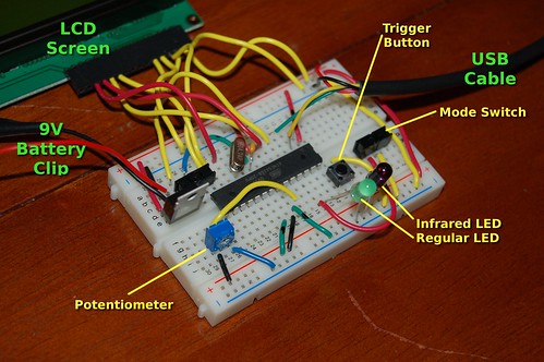
I'm almost finished with my Nerdkit Intervalometer. (An intervalometer is gadget used to take time lapse videos.) I've been working on it for the last 3 or 4 weeks. My goal was to create a project that one could go out and build cheaply and maybe even turn it into a functional gadget. My intervalometer works with Nikon cameras and can be used to take time lapse photos or as a plain old remote control. The only part you'll have to buy besides the Nerdkit is an IR LED ($2.00 or less).
The code is hacked together with pieces I took from the tempsensor and traffic light project. For now, the project only works with Nikon cameras, but I've written some code that should work with Canon cameras. I just didn't have one to test it with. The code is available on my blog, but I'll post it here if anyone wants it. Here is a link to the write-up: http://thedavisblog.com/blog/?p=708 I'm working on a video of it right now. |
|---|---|
|
December 02, 2009 by Rick_S 
|
Cool project and great idea. What ya going to be time-lapsing??? Rick |
|
December 02, 2009 by FWSquatch |
I wanted to do some sunrise/sunsets. I've already done a few. I posted them on youtube. Unfortunately, I'm not very good at it yet. I'm sure they'll get better with practice. |
|
December 02, 2009 by Rick_S
|
I like it. Kind of neat to see. Rick |
|
December 02, 2009 by FWSquatch |
I updated my blogpost to add the video. Still at http://thedavisblog.com/blog/?p=708 |
|
December 02, 2009 by Rick_S
|
Very nice video presentation. You've got a lot more courage than me to get in front of the camera! |
|
December 04, 2009 by n3ueaEMTP 
|
FWSquatch, I didn't know what an Intervalometer was until I took a look at your blog. Your idea is awesome! Too often we build something and people seem somewhat indifferent to our projects (I'm currently working on a model rocket launcher for my son) because electronics can do so many things today. They don't realize the sense of accomplishment we gain from finishing a project that actually works. To that end, great work, keep it up!!! Chris B. n3ueaEMTP |
|
December 04, 2009 by mcai8sh4 
|
"They don't realize the sense of accomplishment we gain from finishing a project that actually works." Well said - it's only when we try to do something ourselves that we can truly appreciate the skill and elegance of other peoples work. I remember being overjoyed when I first made an led flash! This is a great project. Very impressive. You also have done a really good job with the vid and the writeup on your blog to show off your achievements. I don't actually own a Cannon camera, but I do know a bloke who does a lot of digital photography using a Cannon EOS 50D. So I may get myself a IR LED and try this bad boy out. Great work! |
|
December 04, 2009 by mcai8sh4
|
Looking at the specs - the EOS 50D doesn't have IR sensor for triggering - ah well. |
|
January 22, 2010 by Phrank916 |
FWSquatch- This project is the coolest! I'm definitely building it soon. I have a Nikon D40 and just having the remote ability would be cool, much less the time lapse stuff. Awesome! Ted |
|
June 03, 2013 by scootergarrett 
|
I just finished my version of this project, kind of, I was after the time lapse and didn’t care so much about the camera. So I started with a 5 year old camera that has some problems (looses date and time every power down among other things). I took apart the case and soldered wires onto the shudder button and where the battery connects to the main board. I can’t show pictures for oblivious reasons. So at this point I can externally power the camera by supplying 3.9V to the battery and take picture by shorting the other wires together. I came up with this circuit:
I don’t know if it’s the proper way to use a 2N7000 but it works. All the wires where getting cumbersome, and figured I will keep this project so I went all out and made my first prototype board:
pic is before cutting to size. I still need to find a power supply exclusively for this that is 6V or more and 500mA. I had a 200mA supply and the voltage would drop too much when the flash capacitor tried to charge and the whole thing would shut down. So now I just turn the camera on point it somewhere, put it on the lowest quality setting and press the start button, then when I’m done I press the stop button and load the pictures on my computer. I downloaded a free program photo Lapse 3 which works well at turning pictures into a time-lapse video. All I have so far is an hour of people walking around outside by the bus stop compressed into 57 seconds. Things I probably won’t do but would be cool, slowly rotate the camera on a stepper motor, or a motion detection trigger. For completeness the code: |
|
June 04, 2013 by FWSquatch |
Great job! I love your project. Glad to see others do this sort of thing. I wish I hadn't got rid of my Nikon cameras or I'd still be playing with mine. |
Please log in to post a reply.
|
Did you know that NerdKits also has extra parts available for its customers? Learn more...
|


Copyright © 2013 by NerdKits, L.L.C.