NEW: Learning electronics? Ask your questions on the new Electronics Questions & Answers site hosted by CircuitLab.
Basic Electronics » Continuity or just plain connect?
|
November 19, 2009 by Farmerjoecoledge 
|
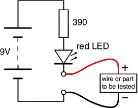
Can someone explain why this is such a big deal... If this is all you need...
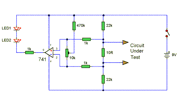
Then what's all this?
Where i come from if you got a circuit that don't connect, you find the faulty wire, trace it until you can find were the short is, and fix it. The point being if it connects it's good if it don't it don't, there's no inbetween. If you got a solder joint it's going to connect or it's not going to connect, that's it. 0.25 to 4ohms come on really. Do they even make resistors that small to set it with? For a intermitent break well you know what those are like. I had one in/before my starter once, total pain. So there's a farmer story for ya, and where's the buzz? Just got a multimeter, the battery that was in it was 6.1v don't know if that's not enough. I put in 9.76v and still no buzz. thx |
|---|---|
|
November 19, 2009 by Farmerjoecoledge
|
That' what i get, does anybody else think there should be an edit button "after" you post? :| Title: Continuity or just plain connect? Mike paste this for me, i got ahead of myself. farmer |
|
November 19, 2009 by mrobbins (NerdKits Staff) 
|
(added thread title) |
|
November 20, 2009 by Farmerjoecoledge
|
Electronics,,,no wonder i spent all my time in the shop. So we find out were going to "short" for a "short" That's right, a very low resistance is equivalent to a "short" or just a wire connecting the leads...ya because were looking for a "short", makes perfect sense, don't you think? I thought electronics was crazy when i seen the same symbol for 3 totally different parts.Now i know why all the nerds in high school looked so confused. So the beeper/buzzer still doesn't work, well everything else does so it's not a total loss. So the continuity vs the connection is going by by, the "short" is where it's at. |
|
November 23, 2009 by BobaMosfet 
|
The two circuits you displayed are not functionally equivalent. One (the COMPLEX one) has an Op Amp (741) in it, and the other does not. With the op-amp, in order for the LED to light it accepts power from the circuit under test, in order to slew the op-amp so the LED turns on. The first (SIMPLE) circuit above, instead, drives power into the circuit being tested. Do you smell something burning....? |
|
November 24, 2009 by Farmerjoecoledge
|
Hey Boba, I smell something fishy, that would make perfect sence if there wasn't any power on the complex one. How do you hook the two powers together? How's it going to read "just" the power from the circuit? No big deal, I'm just killing time, I'm programmer less. |
|
November 28, 2009 by wayward 
|
Hey FJC, I really don't know much about op-amps, but I do know that they have additional power supply leads. They are amplifiers, meaning you use them to generate a strong signal from a weak one while retaining its properties of interest (usually you want to preserve the shape of the signal while multiplying its voltage amplitude, someone might want to correct me here). So you need additional power to generate a stronger swing. You have the same thing going in a guitar amplifier: the signal from the guitar comes from one circuit that contains guitar pick-ups. Additional power comes from the wall plug, AC, rectified and filtered to DC internally, then made to follow the signal from the sensor circuitry. I've seen more op-amp schematics that draw power from the primary circuit, though, which is also fine if you don't need more than, say, 5V or 12V or so. In this case, however, voltage is not an issue; op-amp is used to decouple the circuit under test from the additional power source (battery), as BobaMosfet vividly explained :) Would anyone like to comment on this? Also, I tried to read the schematic FJC posted, and I guess that it works by driving op-amp's V+ input slightly above V- (via 10ohm resistor), which gives high output and LEDs don't light up, unless 10R is shorted, in which case V+ <= V- (that potentiometer in the middle is used to trim this sensitivity threshold?), output goes low and LEDs light. Does this make any sense? |
|
November 28, 2009 by Farmerjoecoledge
|
Yeah me. Comment#1 If your going to buy one of their Mutimeters A830 A930, Don't, because i don't know who makes it because the manual is in Chinese. I had to google it just to find out how to use it, hence the original q. Comment#2 All that matters to me now is that this no name mutimeter also came with a dead battery and it DOES NOT BEEP WHEN THEIRS CONTINUITY so if the battery is dead the thing is useless. Get one elsewhere. Comment#3 If it sounds like i'm chocked i am. I'm sitting here with 8mo's worth of work and nothing , i mean nothing works. So it's between the nerds stuff and the scanners at customs. Two systems that they say works for them, but they don't for me. I've been progrmmerless for 2mo's because i forgot to flip the switch on the adapter back to 6vdc. I have another system that uses 12vdc. The point is i don't understand why i'm still nowhere, so i'm sending the chips, serial and "new" programmer, with their lcd that worked once and quit, back. And then their going to test it and it will majicly all work,again. |
|
November 28, 2009 by Farmerjoecoledge
|
Comment#4 It's good to here from you again Zoran, if anybody can figure this stuff you can. I like your "V+ <= V-" part. So now we have a low powered led too. Well...what i think is, by how much info there is on this continuity thing the electronics guy's had nothing else to bang their heads on until the internet came along. I was blowin all the way "out" to left field with the vastness of the "continuity connection". Just a whole bunch of hot air. Comment#5 Mike, Why don't you post your hack for the foodloader, their no big secret. |
|
November 29, 2009 by Rick_S 
|
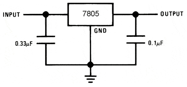
Farmerjoe, I watched your videos on youtube. The "6V" adapter you quote using there without a regulator. What type of adapter was that actually? Based on your statement above, it sounds like one of those variable voltage ac to dc adapters for powering tape players, radios, etc... If so, it doesn't surprise me one bit the results you got. Most of those adapters are not regulated. They use resistors to "drop" the voltage based on an expected load. This works fine for most consumer electronics which have their own power regulation on board or have sufficient load to drop the voltage when the adapter is used. However, the micro-controller has no such protection. It's only defense against over voltage is the designer. That is the purpose of the regulator. Without that, the micro-controller was getting the full 6v (probably more like 9v - 11v no load). Even at 6v, you'd be at the Absolute Maximum operating voltage per the datasheet. (Not recommended) The second problem with adapters like that is poor filtering. Most have very minimal filtering on the power. Some have no filtering. Again, often the device it is being pluged into takes care of that. Often they will just have a bridge rectifier or 4 diodes setup in a wheatstone bridge to convert the ac to dc. In your case there is probably a resistor network that handles voltage reduction as well. The AC noise in the DC output voltage is often quite high. It can easily cause the problems you were seeing in your array. Clean power is a must for micro-controllers. The noise in the power can cause all kinds of wierd behavior. Most of the time, filter capacitors are placed right at the voltage regulator to help clean up this noise. They are optional if you have a clean power source such as the 9v battery the nerdkit comes with. However, their use becomes much more important when you use a non regulated ac adapter. Here is a sample schematic showing the 7805 regulator and filter caps.
You might try putting the regulator back into your circuit, add a couple of capacitors and see if that helps. This will also prevent you from accidentally over powering your kit. If you don't have any spare capacitors, find an old piece of junk electronics and steal some. The values shown in the schematic don't have to be exact. Their main purpose is filtration. Also on a last note, if you do steal from a piece of junk electronics, and you use electrolytic capacitors, make sure you get the polarity right on them. There will be a side marked with a row of - signs pointing to the negative lead. Good luck, Rick |
|
November 29, 2009 by Farmerjoecoledge
|
Hi Rick, welcome aboard! I'm sorry, i guess were not going to go get capacitors, i needed one for the soundmeter and had to buy 20. That's from the only components guy in town, I still got 20, i don't have the sm hooked permanently, too bad their 10uf. That's quite an observation on your part, the 6vdc thing. That's pretty good hey? I got another one that some not all of the letters are upside down. Data Guy is the best so far, oh and by the way, the data wire works for the soundmeter too, no video for that, my programmer fried right after that discovery, makes it jump way more than with the piezo. You don't know me very well yet, don't take offense, but i've posted my share since jumping on the nerds wagon, and this last part with the programmers/chips is all by the book checked and rechecked again. My last, and i mean last attempt at getting this to work, new chip and cable and the dam thing flashed with ledarray2.c, yes we got life :( End of sad story, it doesn't run the test pattern hello, it also doesn't take one of my famous feeds, opens and closes the connection, that's it. Me and the boss are going to straighten this out eventually or i might go ardri$. Welcome! again to the "continuity connection". You sound like you'ld like the nanotech, check it out. fjc |
|
November 29, 2009 by Rick_S
|
If you built them by the book, I didn't realize. The youtube videos didn't show that at all. What they showed was an alternate power source you stated was 6v with no regulator on the board. What I was trying to let you know is that the scenario you had there could easily cause the odd behavior in the display and could have even fried your mcu. The reason the "data" wire helps the erroneous behavior is most likely due to the fact your body is probably changing the capacitance on the wire plugged in. Kind of like the pumpkin tutorial only yours is accidental. As for capacitors, 10uf capacitors would definitely help filter power. I've used 100uf before to help clean up power. If by your "End of sad story" statement, you mean you are through trying to figure it out, I'll be sorry to see you go. There isn't a whole lot of traffic in this community. I've been trying to do my share - helping out where I can. I know I've seen you try to do the same. Good luck with it all, Rick |
|
November 30, 2009 by Farmerjoecoledge
|
Thanks for the well wishes there Rick, Us nice guy's are hard to find. Ever run down linux in one of their forums? Man they get down right nasty. You got me goin and i checked my regulator's, the one that i was using in the video is 7.2vdc up from 6vdc. OOpps, i had no idea, i just got the multimeter and just realized that's what it's for. The other one is worse, 19.1vdc for 12vdc down to 4.1vdc for 3vdc. Ths 6vdc setting on there is 8.9. This is what people buy trust and use and can't figure out why the 12vdc light keeps "frying" That's mind boggling, what kind of rip off species are these fuckheads. Thank god i was using the voltage regulator for these new chips. That will explain why my whale tail display quit, gradually. So thx for the heads up. fjc |
|
December 08, 2009 by BobaMosfet
|
Farmerjoecoledge-- Sorry, I've been away for awhile, so I couldn't get to this. Your question: "Hey Boba, I smell something fishy, that would make perfect sence if there wasn't any power on the complex one. How do you hook the two powers together? How's it going to read "just" the power from the circuit? No big deal, I'm just killing time, I'm programmer less. " Take a look at the schematic with the 741 Op-Amp. Pins 7 & 4 provide the power to the Op-Amp for Amplification. Pins 2 & 3 provide the discrete (what you are testing) signals. - By default, the Op-Amp wants 2 & 3 to be equal. - Pin 6 will output based on what you connect pin 2 & 3 to. - Pin 6 will output whatever the 741 thinks is necessary in order to make 2 & 3 equal. In this case, the feedback loop is on pin 3 (non-inverting input). Which makes pin 2 the reference. It will adjust pin 3 either plus or minus as fast as it can, in order to get it to match pin 2. Pin 6 will output whether it is putting out a positive or a negative value. Since the LEDs are pointed the way they are, they will only light if pin 6 is outputting a value headed toward common or negative. If that seems a bit confusing, and you're wondering how I got there-- it isn't simple. It takes a lot of learning to get a grasp on how voltage .v. current behaves, how op-amps work, and how transistors work (the basis for an op amp) - etc. The resistors in the circuit are merely voltage dividers and a means to limit current or bias the op-amp (fine tuning). To answer your question- the powers are NOT hooked together per se. The op amp provides a means by which the power from one circuit (the one being tested) can influence the operation of the other (the tester). I don't know your level of learning in electronics-- my feeling is that you got into this with Nerdkits and want to learn-- but your floundering a little-- perfectly understandable and everyone's been there. With that said, please consider these words: To answer perhaps another question in your mind, you CAN LEARN this. It isn't easy, but it isn't impossible either. The first year is the hardest-- and will only get harder and more confusing IF you don't stop, and consider starting with a book on basic electronics to get some of that stuff under your belt. If you spend 1, 2 or 3 months learning basics like that, it will save you endless frustration, confusion and more. And then come back and pick up where you left off-- things will make SO much more sense. It's the way it always is when someone tries to learn on there own-- I've done it countless times-- It's hard, frustrating, confusing. Tiring even. But if you perservere, the light bulb will go off for something, and then later again, and then later again still. And then again, and again, until you are building on what you know and pulling together those things that are now confusing and saying... Aha! I hope this helps you, we look forward to more questions! |
|
December 08, 2009 by Farmerjoecoledge
|
Hi Boba, There, see, it all makes sence. You just gotta find the right people. Electronics is avr's, I'm just learning whatever happens to be passing by, it's all good, and your right again when you say things start bumping into each other, and some lights come on. I'm a late blummer but i think i'm a little too many grey ones already, learning linux was bad enough. I'm workin on a good question keep your eye out for "The Protocols, from code to chip" Farmer |
|
December 09, 2009 by Rick_S
|
Very well spoken BobaMosfet. I too have been through the beginning horrors of self learning. I think that is one of the reasons I've been trying so hard to help Farmer through this. Grant (Farmer), Boba's recommendation for basic electronic books could be very helpful. Some books that may seem almost too basic but really provide the good building blocks (I still reference them once in a while) are those by Forest Mims III. If you search amazon you'll find them. Radio Shack sold them years ago and they are a goldmine of information with lots of small projects you can build. These are meant to help people understand a bit more of what the various components do. I think the best thing about them is the fact they are written with the beginner in mind. When you say " I'm a late blummer but i think i'm a little too many grey ones already ", don't talk yourself into the I'm too old for this stuff. I have a few of those grey's as well and I refuse to let them get in my way. I'm sure you can do it. Stick to it and it will click eventually. Then you will look back at all this as you are trying to help someone else through it with the experience you gained on your journey. Rick |
Please log in to post a reply.
|
Did you know that you can read diagnostic data from some cars with a NerdKit? Learn more...
|


Copyright © 2013 by NerdKits, L.L.C.