NEW: Learning electronics? Ask your questions on the new Electronics Questions & Answers site hosted by CircuitLab.
Basic Electronics » Understanding LEDs
|
November 06, 2009 by mikedoug |
Alright... So I set forth today to play around with the n-channel mosfet, and used some resistors and an LED in the process. The mosfet stuff worked just like I expected. I think I need some assistance understanding the electrical characteristics of the LED... The LED stuff I need some help with -- I'm a numbers person, and to that end I'm a "numbers need to add up" type of person. The answer here may just be "plus or minus is good". I put a resistor in series with an LED connected to a +5V source. Below is a "table" of values (Vr=voltage across resistor, Vl=voltage across LED, I=current in circuit, Rr=resistance of the resistor) In all three of them, the voltages sum up to 4.96-5.02V -- Excellent! So what I learned from doing this is that no matter what voltage you give the LED, it's going to force an ~ 1.8V drop across itself; and it's going to force the rest of the drop to be across the resistors. What I don't understand, is how do you plan for the effects an LED is going to have on a circuit? If I remove the LED in the 333Ohm case, then I get (or should get) roughly 15mA of current. How do I know (before I put the LED in place) that the LED is going to cause a drop of the current to 12.73mA. That would seem to indicate that there is some sort of resistance in the LED causing the 2.27mA reduction. With a 5V source, and a current of 12.73mA, the total circuit would seem to possess 393 Ohms of resistance. What's interesting is when you look at that same calculation for the 1KOhm resistor numbers. With a 5V source, and a current of 6.44mA, the total circuit would seem to possess 776 Ohms of resistance -- LESS than the 1KOhm resistor in series with the LED. It's as if here the LED is forcing the resistor to overload itself and draw more charge than Ohms law would dictate (1.44mA more). Inquiring minds want to know! |
|---|---|
|
November 06, 2009 by mrobbins (NerdKits Staff) 
|
Hi mikedoug, I think something might be wrong with your data / measurements. The current "I" should be equal to Vr / Rr in each case. (In fact this is basically how current is measured -- by looking at what voltage drop it gives across a known resistance.) So for your three Vr/Rr pairs, I'd get: 9.51mA, 6.34mA, 3.21mA. Before we get to bigger picture questions about how an LED effects a circuit, I think we should get to the source of these measurement issues. It indicates that either your resistors aren't really what they say by well more than the allowed +/- 5% tolerance, OR your multimeter is somewhat broken (this happens!!!), OR the multimeter itself is altering the circuit, OR maybe you're just not measuring current in the right way. How are you making each of the measurements? Mike |
|
November 06, 2009 by mikedoug |
I guess that's what I get for having a 9V battery in my multimeter that was only putting out 7.6V instead of 9V!!! To my multimeter's credit, it has been telling me "low battery" for a while... Let's see what happens after I replace the battery: With JUST the resistor and the 5V source in place, here's what I get (all of these measurements come from the multimeter): Next I place one of the red LEDs from the nerdkit in series with the resistor, and I get the following: Now THAT makes sense! The LED is sucking up a 1.75V drop, leaving the resistor with a 3.22 (~3.25) drop. 3.22 V / 991 Ohms = 3.25mA!! Okay -- so two things learned here:
So if I wanted to burn the LED at the maximal 20mA (steady), I'd need ~ 162 Ohm resistor at 3.25V? (3.25V / 162.5 Ohm = 20mA) Taking that a step further, if I put TWO LEDs in series with a resistor, the LEDs would consume 3.5V of the 5V, leaving only 1.5V to drop across the resistor. To get those to burn at 20mA, I'd want a 75 Ohm resistor? (1.5V / 75 Ohm = 20mA). From experimenting, this would seem to be true. I just added a second LED in series with my test circuit above, and I get: So the drop across the LEDs is around the range of 1.7-1.8 (from my experience with them). Where can I find that information in the spec sheet? Is this the forward voltage? What then if there's a third? Ohms law is violated and blows my pieces to bits? Here's what I got Let's just say that they "lit", but only so very faintly that you can barely tell. So this got me to thinking. I've got three of these things in series, and the 5V just doesn't cut it because it puts the drop across the resistor so small as to not generate any current at all. The power supply I use is from an old MX1000 Logitech mouse which puts out 8.6V -- I feed that into the 5V regulator. Some quick math: 8.6V - 1.7 - 1.7 - 1.75 (guessing at green V drop) = 3.45V. With a 1000 Ohm resistor, that would give me ~ 3.45mA. Sounds safe, so let's test it out! Here's the actual measurements: Perfect! My original guestimates were off because I underestimated the drop across the green LED, and the red LEDs jumped up by 0.5V each. Never-the-less, this is all making sense. Now I just need to figure out the "why" of the voltage drop across a non-resistant device. I understand voltage dividers when it comes to resistors in series -- but these LEDs enforcing a voltage is odd indeed. I know I do long posts, but I'm going to get this stuff down! MikeDoug |
|
November 07, 2009 by adil |
By Law: The Current should't change at all, regardless of the resistance used in SERIES to LED. I mean, with all resistors the value of current should be the same i.e. Out of the battery? Ir = I_led = Vr/Rr = V_led/R_led What do you say? |
|
November 07, 2009 by mikedoug |
This is true, the current doesn't change -- but the LEDs affect the voltage drop across the resistor, and so there is a "change" in current as you add/remove LEDs. What I'm after is understanding why/how the LEDs "force" this voltage drop across themselves. Actually, I'm confused by your statement "regardless of the resistance used in SERIES to the LED". The current should change directly in relation to the resistance used in series to the LED(s). Here's a page that confirmed what I had experienced yesterday: http://www.theledlight.com/LED101.html. So now that I know how to treat LEDs, I'll be able to more appropriately calculate for them in the future! MikeDoug MikeDoug |
|
November 07, 2009 by adil |
I am still trying to understand the myth. But meanwhile I found this calculator that solves exactly the problem you are dealin with LED resistance calculator |
|
November 07, 2009 by mikedoug |
adil -- very good link! I enjoyed it. |
|
November 07, 2009 by mrobbins (NerdKits Staff)
|
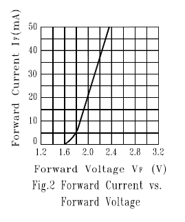
MikeDoug, As to your question of "why/how the LEDs 'force' this voltage drop across themselves", I think it's important to go back to the issue of how to define any two-terminal electronic component. Imagine a black box with two wires coming out. For now, assume that whatever's inside can't store energy or information. If you're asked to characterize the device inside the box, how can you do it? There's really only one way: apply a bunch of different test voltages and measure how much current passes through. (The opposite, which is to apply a bunch of different test currents and see how much voltage drop there is, is totally equivalent.) You then generate a graph of I vs V. That graph of current versus voltage is the only real description we can make without peeking inside the box. (If the above paragraph isn't clear, then think about a fluidic system -- a bunch of pipes -- with two terminals. Assuming the pipes don't leak internally, then all the water that goes in one side will come out the other. When all you have to work with is the two terminals, the only way to characterize the system is to apply a known pressure difference with a pump, and see what flow rate results. And all we can do is to graph flow rate versus pressure. Thinking about the system in this way lets us treat the insides as a black box, and only worry about the relationship between the fundamental variables at the terminals. In the electrical system, current is the rate of flow of charge (Coulumbs per second), and voltage is the measure of how much energy it takes to move one unit of charge through that system (Joules per Coulomb).) Like we talk about early on in The NerdKits Guide, you can make a graph like this for any two-terminal device, and we show a few like a voltage source, current source, and resistor. But LEDs have one too, and you've actually started to measure a few points on yours with your measurements above -- just graph the I versus V to see what I mean. I'm going to look at the one from the LTL-307EE datasheet, which is a red LED like the one that came with your kit. Here it is for your convenience:
It's a continuous curve, and you could probably come up with a fancy mathematical model to fit it well. (Voltage would be something like a logarithm of the current (due to the p-n junction) plus some part proportional to the current (due to resistance).) But we can make a really simple linear model, which is that over the region between 1.8-2.2 volts, it "looks like" about a 12.5 ohm resistor in series with about a 1.73V voltage source. (These numbers will not exactly match what you're measuring, because of temperature variations, manufacturing variations, etc, but they will probably be within ~10% of the truth under normal circumstances.) So the why/how question has answers on a few different levels... first that "the black box makes it so" -- i.e. to push 1 gallon/second through that (non-linear) pipe simply requires 10psi of pressure. Second is that the semiconductor dynamics of the actual junction within the LED lead to some exponential relationship between I and V, plus some series resistance. And finally, we can take the actual I-V plot of the device, whether from the datasheet or from your measurements, and make a simple model we can work with. The only truth is the I versus V plot, and the rest, like saying "The LED will always steal 1.75V", is a (admittedly quite useful) simplification of that. Adil, There is no R_led. If you look at the I-V plot of a resistor, it is a straight line through the origin, so it's really convenient to define a resistance from that. But for nonlinear elements, it doesn't have any meaning. At the risk of potentially confusing you more... for non-linear circuit elements, like LEDs, you can define something called the "small-signal resistance", which has to do with the slope of the I-V plot about some given point (actually dV/dI), with the idea that we can often consider them to be linear over some narrow range of operation. This is the 12.5 ohms above. But it's not too useful to talk about the total voltage divided by the total current at any one point on the curve, and it's equally not meaningful to call that a resistance. Please let me know if this is helping you all get a better understanding, or if not, what's still unclear. I think this is a very common issue of confusion so let's figure it out! Mike |
|
November 07, 2009 by mikedoug |
I typed up this huge response, trying to reason through the math... and then it struck me: You just say, "I want to run it at 20mA, and I know @20mA it's 2V"... So then the calculation is this: So if VS were 5 volts: If you wanted to run it at anything other than 20mA, then you're going to have to hunt-and-peck? The 150 Ohm solution at least gives you the LOWEST value resistor that you'd want to give it, or is it just smartest to give it exactly what it wants to hold that 20mA? MikeDoug |
|
November 07, 2009 by mikedoug |
Heh... After going through this entire journey, I went back and read rusirius' response to my other thread about using the MPU pins to drive the LEDs... He had the exact same calculation: assume 2V drop per LED, solve for 20mA -- oh look, for a 5V source, it's 150 Ohms... :) MikeDoug |
|
November 23, 2009 by BobaMosfet 
|
Let's add something to this. First of all- you can't assume. In electronics you must NOT assume. That is how you burn components up, or worse, or not get them to work at all. This is, after all, ENGINEERING. You have to start with knowns. What are your knowns? You know your source voltage. You also know you have an LED of a specific color and material type. The type of LED, and it's color, determine how much voltage ir required to "fire" that diode, and how much is too much (will fry it). The only safe assumption is that you want to try to run no more than 20mA of current through your LED. This is fairly universal and not so much an assumption, as a rough standard. As such, all you need to know is how much voltage it takes to cause your LED to fire. (or any diode for that matter). If you cannot find a specification, then use your meter's diode tester-- it will tell you exactly how much voltage is required to cause the LED to light up. Once you know that, you can calculate the rest easily. For example, most Red LEDs of the common AJGaAs variety require 1.63 to 2.03VDC (or 1.83VDC to be right in the middle) to fire at approximately 20mA. Thus, knowing this, the formula is simple for the appropriate resistor: Other LED colors and material types may "fire" with more or less voltage (from 1.63 to 4.4VDC) As for how it affects other parts of the circuit, remember to think about parallel .v. series. Just keep the LED as a series circuit unto itself, and the rest of the circuit will have no effect. |
|
November 23, 2009 by BobaMosfet
|
To add one more thing (to my post above this). Let's say you want to run at 30mA instead (to answer your specific question about hunting and pecking'). That's easy-- just work the formula the other way: *Now, you probably have to go with the next nearest equivalent resistor, which is either 100 or 110 Ohm. You can run the calculation the other way to see how much current that actually runs through the LED: or See... it ain't so hard :D --- Rely on the math. Rely on the MATH. :D |
|
February 01, 2010 by sepeters |
This is a great thread for me because I haven't done any real LED electronics since college and there was only one set of electronic characteristics for them back then :) I have some LED's that I've got some notes on when I bought them over the last couple years but I don't have spec sheets. Is there a way to determine (other than doing a lot of samples) what the characteristics of an LED are, and is there a good place with a chart of the typical characteristics for the different color LED's? Steve |
|
February 06, 2010 by BobaMosfet
|
Steve To be honest, it doesn't really matter what the characteristics and materials are for the LED. Just use your Diode Tester function on your multimeter (if your multimeter doesn't have this, get one that does- they are not very expensive). This will tell you the voltage drop required to pull just enough current through the LED to fire it. Use that value, and 20mA current value to calculate the size of resistor you need in series with the LED to keep it happy and safe. BM |
|
February 10, 2010 by sepeters |
BobaMosfet - Thanks for the feedback, I've been looking at getting a new MM since my fluke is about 15 years old and doesn't have some of the cool new MicroE features. Knowing what it tells me on that LED testing function was the key! Now off to the store... =}----- Steve |
|
March 01, 2010 by michaeldallas |
Dave Jone's EEV blog has a several good videos on MM's. As stated above, the MM can change the circuit and not all MM's are the same. Here are a couple of his videos that should help: Burden voltage (on the MM): http://www.eevblog.com/2009/04/08/eevblog-2-burden-voltage-and-hp-multimeter-review/ Why cheap MM suck: http://www.eevblog.com/2009/04/29/eevblog-6-part-2-of-2-why-cheap-chinese-multimeters-suck/ |
Please log in to post a reply.
|
Did you know that a square wave sounds different than a sine wave? Learn more...
|


Copyright © 2013 by NerdKits, L.L.C.