NEW: Learning electronics? Ask your questions on the new Electronics Questions & Answers site hosted by CircuitLab.
Microcontroller Programming » How to use Coin Collector Ouput?
|
May 25, 2014 by lnino 
|
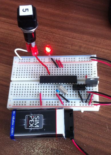
He guys, some time went by since my last activity. Now I have more time for my MC Projects. At the Moment I am trying to use a coin collector for triggering an Event. I have bought and programmed the following coin collector: LINK On the Coin Collector I have two switches. NC (Normal Closed) und NO (Normal Open). When the switch is set to NC, then you will see on the Coin cable 0V. After insering a coin you see 1,3V as Long as the pulse takes, after that again 0V. When the switch is set to NO, then you will see on the Coin cable 5V. After insering a coin you see 3,6V as Long as the pulse takes, after that again 5V. This is how the device works. Now I want to Trigger to turn of an LED when inserting a coin. Can I do this like a normal Switch connected to GND with pullup resistor? Or do I have to read the voltage like meantioned in the temp sensor Project? I want to replace the button in this screenshot with the Input of the coin collector. When I am able to do this, I can Count how Long the pulse takes to figure out if a 50cent, 20cent or 10cent coin has been inserted.
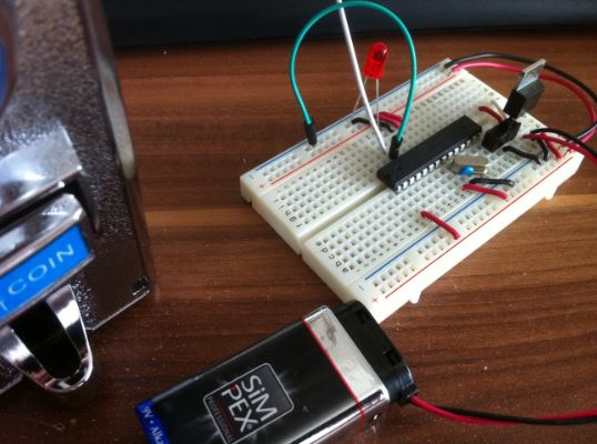
I have tried to connect the coin wire (White wire) to PC2 an put one wire to GND like a Switch, but the LED keeps unlighted. Maybe because its connected to GND all the time.
You will find the code I used for this Project below. I have just used a simple Interrupt for the button press. Thanks for your help, maybe you can tell me an easy way to get this working? |
|---|---|
|
May 26, 2014 by sask55 |
Inino I have a couple of questions just to clear up my understanding of your problem. Is your setup working with the push button as shown in your first picture? You appear to be using a battery to power the Nerdkit board. Are you using a power supply for the coin counter? If you are, is it a common supply with the Nerd kit or at least are you sharing a ground between the two power supplies? Where are you getting the voltages that you have quoted? Are you measuring them from the nerdkit ground? Are those voltages measured when the coin collector output wire is connected to the micro’s input pin or when the counter output is an open circuit not connected to anything? As long as you have you input pin tied to ground as in the second picture the voltage to that input pin will always be 0V. For certain that is not correct as it is shown. Assuming you are running the Nerdkit board at 5V. From the ATmega datasheet Vil - Input low voltage Max value is 0.3VCC = 1.5 Volts. Also Vih Input High voltage minimum val is 0.6 VCC = 3.0 Volts. The voltage values that you have quoted seam somewhat strange to me. In NC mode the 1.3 volt level is not above the 1.5 volts required make the input pin go high. In the NO mode the 3.6 volts level is not low enough ( below 3.0 V) to make the input pin go low. If that is the case neither of the modes can be used to directly drive the input pin. If I am understanding this correctly you will require a simple transistor A 2n7000 from the nerd kit should work to produce a full 5 volt signal level change as the coin counter output changes. I suspect that should not be required. I think it is likely a case of gaining a better understanding of the output levels from the counter. I have not looked closely at the specifications for the coin counter. As far as the micro goes, it should read the output from the counter as long as the voltage changes to the input pin are large enough to trigger a level change at the input pin. Again the voltage level at the input pin at referenced from the Nerkit ground. I think it is important to recognize that the output from the counter is not simply a switch that is ether open or closed. It is a signal voltage produced by the coin counter and in order to make use of that signal you will require a common ground. I hope this is of some help. |
|
June 01, 2014 by lnino
|
Hi sask55, sorry for my late reply and thanks for your detailed answer. The main mistake in my project was that I haven't used a common ground, like you said. After I corrected this, I modified the temp sensor code to read the output of the coin connector. Now I am able to differ between different coins with my nerdkit. At the moment my code is really quick and dirty, but I will upload it when I overworked my code. Thanks for your help. greeting lnino |
|
June 01, 2014 by sask55 |
You’re welcome. Glad to hear it is now working. If this project is to be long lasting or more or less permanent I would consider losing the battery to the Nerdkit board. I assume that you have the coin collector powered by some type of 12V DC power supply as the specifications indicate. If that is the case it would be convenient and simple to use that supply to power the Nerdkits micro as well. Since you are sharing the ground now, all that would be required would be to connect the +12V from the supply to the high voltage side of the voltage regulator in place of the battery connection. To be on the safe side to help to avoid issues from possible voltage fluctuations on the supply you could consider adding a larger value capacitor in parallel to the +12 V. Since I happen to have a few 4700 uf capacitors around that is what I world likely use, but any larger size cap should help to flatten out possible spikes and dips on the supply. Since the current drawn by both the coin collector and the micro are small even a 150uf cap could add stability. Depending on the quality of the DC voltage from the supply it may not require any cap at all and work just fine without any. |
Please log in to post a reply.
|
Did you know that negative numbers are represented in two's complement notation in binary? Learn more...
|


Copyright © 2013 by NerdKits, L.L.C.