NEW: Learning electronics? Ask your questions on the new Electronics Questions & Answers site hosted by CircuitLab.
Microcontroller Programming » Trouble Wiring AVR ISP mkII programmer to mcu, please help.
|
September 30, 2012 by fishberg5051 |
Hello, I'm having some serious problems wiring a programmer up to an MCU (I've tried two so far (1284P, and 162), and when I go into atmelstudio 6.0 and try to read voltage it ALWAYS returns 0. I simply can't seem to figure out how to get past this and need a push in the correct direction. The User Guide I've read defines the programmer (ISP) pinout as the following: 1: Miso 2: VCC 3: SCK 4: MOSI 5: RESET 5: GND so I give the MCU power (5v), and plug in the wires to it's corresponding pins Miso -> Miso SCK -> SCK VCC - 5v rail GND - GND rail MOSI -> MOSI and finally the rest to the RESET pin (I've read in a few other forums that some suggested adding a 10k resistor on the reset line and did that and no luck yet) I've also read that some programmers supply the voltage so I unplugged my power source and tried the programmer only with no luck. I've even tried measure voltage from the vcc/gnd pins from the programmer and feel mine does not follow this trend for no voltage is read. I'm very stuck on this and I'm open to any suggestions anyone might have. My overall goal is to get my 1284P programmed which opens up to a new series of questions but I'd love just to be able to get some type of reading first. pictures and screenshots can be shared as well but not sure what to take a picture of yet. Thanks in advance. |
|---|---|
|
September 30, 2012 by Ralphxyz 
|
lets start with what programmer you are using? They do not all have the same power requirements. The ATmel AVRSPmkII requires that the "target" be self powered. The ATmel Dragon powers the target. Ralph |
|
September 30, 2012 by fishberg5051 |
Hey Ralph, I am using the atmel avrISP mkII. (url: http://www.atmel.com/tools/avrispmkii.aspx) it's definitley not the dragon. Let me know what else I can provide. Thanks |
|
October 01, 2012 by Ralphxyz
|
Duh of course, with the avrISP mkII the target has to be powered. The led (not the one next to the USB connection will be red if there is no power to the target and green if there is power. I just discovered that you only need 2 volts to power the target but you can not program at 2 volts but you can view and set the fuses etc. What are you using for a target? If you are using a breadboard then some pictures might help. Well pictures of your wiring no matter the target might help. Chances are it is a wiring error. Ralph |
|
October 01, 2012 by fishberg5051 |
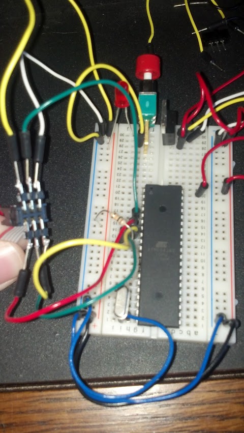
Hey Ralph, Thanks for taking the time to help. I attempted to take a few pictures to show the wiring. My overall goal is to get a 1284p programmed but in this image I'm testing on a 162. What strikes me as odd is, when I read the voltage the programmer remains red (no target power), but when I attempt to read the device signature it tells me there is no power then changes the led to green as if connected but it can't get into programming mode. Anyhoo, here are some pics:
It may be somewhat difficult to see clearly but I think my other post above described what pins I'm going to from the spi. I have no doubts I have a wiring issue somewhere but I just can't seem to figure anything out. Oh, and I think I mentioned I was using a 10k resistor on the reset line, and I was reading the mkII user manual and they suggested nothing larger than 4.7k on the reset line, and I don't have any that size for now so I went with a 1k which may be to small. I've tried a lot of different things and I'm willing to try anything more. thanks again |
|
October 01, 2012 by Ralphxyz
|
fishberg5051, is it just the angle or do you have the MOSI pin going to pin 5 on the 162 MCU? It should be going to pin 6.
Is everything just off by one? Also the ATmega 1284P is not list as a supported device in the avrISP mkII User Guide I found on line but that might be a old version the ATmel 328 is also not listed. Ralph |
|
October 01, 2012 by fishberg5051 |
I think it's just the angle of the picture. Looking at my board in front of me and mosi is on 6. Miso on 7, SCK on 8 and Reset on 9. VCC on 5v rail, GND on GND rail of breadboard. also I hope your looking at an old user guide. When I bought this thing from atmel's store I saw the supported devices list: http://store.atmel.com/PartDetail.aspx?q=p:10500054 <-- not sure if this works and it lists the 1284p, 328 and 328p etc. :D I'm just baffled, it's gotta be something simple I'm overlooking. Don't quit on me yet for ideas Ralph :D |
|
October 01, 2012 by Ralphxyz
|
Good I thought it might be the angle. Actually I was hoping that was the problem and you would be good to go. These types of problems can be very aggravating. I tried to find a 40 pin SIP Target board on Google but did not find anything. You could have a defective motherboard. Do you have a continuity tester to ring out the board and wiring? Ralph |
|
October 01, 2012 by Noter 
|
Is that resistor on the reset pin going to gnd or +? I think it should go to +. |
|
October 01, 2012 by fishberg5051 |
Yeah it's been pretty tough to troubleshoot this. And to answer Noter's question, the resistor is going to the +5v rail, not GND. A co-worker suggested putting a 10k resistor from pin 2 (vcc) to grnd to drop 5v to 3.3v for that worked for him so I might try that. |
|
October 01, 2012 by fishberg5051 |
So in anyone's experience, how often to ribbon cables go bad? Trying to measure voltage through the ribbon cable and I'm getting nada :O ...might be my issue, still trying to confirm it. |
|
October 01, 2012 by fishberg5051 |
Doesn't seem to be my cable, for I was able to plug into an spi port on a manufactured board I have and it read the voltage off it just fine (uses an atmega 128). Just can't win. Time to quit for the day and come back fighting tomorrow. |
|
October 01, 2012 by Rick_S 
|
It looks like your plug is wired backward. The keyed side of the plug typically is the side with pin 1. The key appears to be at the top of your photo, which would show pin 1 going to 5V like Ralph said. Rick |
|
October 01, 2012 by Noter
|
I must be going blind. I've looked again and both your photos show the resistor going to the blue rail. |
|
October 01, 2012 by Noter
|
Rick, does that mean the graphic Ralph posted is for the socket instead of the plug? That would explain why it is wired backwards. |
|
October 01, 2012 by Ralphxyz
|
That graphic is from the AVRSPmkII user manual so it illustrates the socket. Ralph |
|
October 01, 2012 by fishberg5051 |
oh boy do I have an embarrased look on my face! That did not even cross my mind! I swapped the wires and it works like a charm! Thanks so much Ralph and to everyone who commented. Now I can start looking into all the fun of programming a chip...more questions to come on a new thread soon I'm sure lol! Thanks again everyone! |
|
October 02, 2012 by Ralphxyz
|
So fishberg5051, are you going to try to put the bootloader om the mcus? That should be interesting. Of course you can just put a .hex program file directly on the mcu using ISP. Ralph |
|
October 02, 2012 by fishberg5051 |
Hey Ralph, Ya I've been playing with loading the program directly onto the MCU, but I thought it would be a good learning exercise, plus if I keep getting my wires mixed up I'll probably end up frying my programmer at the rate I'm going :P haha! Once I'm done playing with the programmer, I'm going to start learning with the jtagice3 debugger. I figure the more I can the learn on this stuff the better and I can then make my projects in no time. :D Cheers |
|
October 02, 2012 by Ralphxyz
|
You have a debugger in AVRStudio that would be great to learn. Glad you have it all working. Ralph |
Please log in to post a reply.
|
Did you know that binary numbers use base 2 to represent numbers, and these are important for understanding microcontroller registers? Learn more...
|


Copyright © 2013 by NerdKits, L.L.C.