NEW: Learning electronics? Ask your questions on the new Electronics Questions & Answers site hosted by CircuitLab.
Support Forum » strain gauge problem
|
June 28, 2012 by JTOME |
I've finally got the digital weight scale project up and running, but now I have a problem with my load cell. Instead of the weight scale the tutorial shows hooked up, I am using a single load cell connected to the amp. My problem is that if I jiggle the wires attached to the strain gauge of the load cell, the weight changes. This of coarse shouldn't be, there should only be change if load is actually applied to the load cell. Any thoughts on why there is sensitivity in just touching the wires? Thanks in advance. |
|---|---|
|
June 28, 2012 by JTOME |
In addition to my initial post I should also mention that I tried a couple of other load cells that are similar to the first one, and they too have the same results. Also, I checked my values in the hyperterminal, and they too change when I just touch the wires of the load cell. |
|
June 28, 2012 by sask55 |
JTOME When you say touching the wire are you making contact with the conductor (metal) parts of the wire or just the insulation (plastic) covering? Load cell usually work by measuring very small changes in the resistance thru the load cell. By contacting the wires that are connected to the cell you could be putting your fingers in parallel to the load cell. The resistance thru your fingers is certainly small enough to change the reading of a load cell circuit. |
|
June 28, 2012 by Ralphxyz 
|
Also there could be a capacitance factor from touching the wire possible even the insulation. You might try adding some small capacitors between the wire and ground. Ralph |
|
June 28, 2012 by sask55 |
One more thing to consider, Make certain that all of the connections between the load cell and the Amp are very good. Good solder connections or good tight mechanical connections, screw or clamp type. If there is any movement at all in any of the connections this would likely be a source for subtitle resistance changes. Even very small changes of resistance in that circuit that will show up as changes to the readings you are getting. Darryl |
|
June 28, 2012 by Ralphxyz
|
Exactly remember you are AMPLIFING your signal so everything about it gets amplified. Ralph |
|
June 29, 2012 by JTOME |
Sask55 and Ralphxyz, thanks for your comments. I can say that the wire sensitivity is present even when touching the plastic insulation of the wires. Ralphxyz, you mentioned trying small capacitors between the wire and ground. Where on the circuit would this be? Since there are only 4 wires from the load cell, 2 connected to the amp (sense) and 2 connected to the MCU (excite), would it be one or both of the sense wires? |
|
June 29, 2012 by Ralphxyz
|
You could try both of the sense wires. Ralph |
|
July 10, 2012 by JTOME |
I couldn't quite get the capacitors to make an improvement in the noise, so I am instead trying a different amplifier that I've purchased. I have in the past used the following amp seen here: http://www.elane.net/index.php?go=loadcell_amplifier_pro My question now is how do I hook it up to the MCU. Currently the strain gauge (load cell) wires are connected to pins 2 and 3 of the amp, while the excitation wires are connected to pins 5 and 6 of the MCU. However, I've always connected the 4 wires to the left side of the amplifier I've purchased. |
|
July 10, 2012 by Ralphxyz
|
Not exactly sure about exactly what you are doing or asking but:
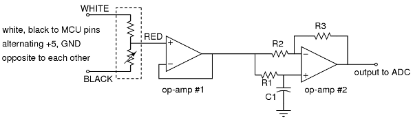
Why would you have the excitation wires connected to to the mcu? Only the the output of the amplifier should be going to the mcu. Maybe I am just not following what you are saying. There are a lot of discussions here in the Nerdkits forum on Strain Gauges. I had a bit of a rough time getting mine to work but eventually got it going. Here is a circuit that really helped me:
The note "white, black to MCU pins" does not make any sense, but I really do not remember much about how I did this but I did get it working. It is your Sense wires you want to amplify and then go to your mcu ADC. Ralph |
|
July 10, 2012 by Ralphxyz
|
If your excite wires are going through the mcu they are limited to 5 volt at @ 45ma. I do not know what that would mean to the Sense voltage/current. I ran my excite wires directly from my 5 volt nerdkit regulator, at that I had to amplifly a minute Sense voltage as it was. I suppose you could use the mcu to turn on/off the excite voltage by making your pins high or low on the mcu. I just always assumed the scale would be live, while the mcu was live. Ralph |
Please log in to post a reply.
|
Did you know that inductors try to keep their current constant over short periods of time? Learn more...
|


Copyright © 2013 by NerdKits, L.L.C.