NEW: Learning electronics? Ask your questions on the new Electronics Questions & Answers site hosted by CircuitLab.
Basic Electronics » Stepper Motor Programming
|
June 18, 2012 by Ralphxyz 
|
This is going to be a on going thread as everything leads to more questions! Not that it matters but I am making a Pan/Tilt mechanism using Stepper Motors and not Servos. I am attempting to use PORTB with PB1,PB2, PB3 and PB4. So here is my first problem with my code. At the beginning I have a #define: When I try to compile I get this message: Line 94 looks like this: I have never tried to use a #define before! I also tried with using Bit Shift instead of Bit Value and get the same error. I am trying to read up on using #define but so far I cannot see my error. Thanks, and this is just the first of many questions I will be having. Ralph |
|---|---|
|
June 18, 2012 by Ralphxyz
|
Oops here is another associated error: I did something and moved the first error to line 96 instead of line 94. I am still getting the same errors. Ralph |
|
June 18, 2012 by Ralphxyz
|
Damm you have to payattention to wha you are doing. I had forgotten a ; on the previous line!! Duh, this is going to be a long road. Ralph |
|
June 18, 2012 by sask55 |
Hi Ralph. For one thing it appears you have an exra ) after the 3 in the definition statment should be |
|
June 18, 2012 by Ralphxyz
|
Good eye sask55, thanks!! Ralph |
|
June 18, 2012 by Rick_S 
|
What are you driving the stepper with? If the L298, it's simpler with it's counterpart the L297. Rick |
|
June 18, 2012 by Ralphxyz
|
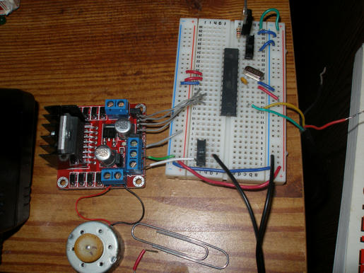
I am using a Stepper Controller off Ebay Hey Mike and Huberto once again the "Links" are not working!! Here is the link for the controller: http://www.ebay.com/itm/261002237340?ssPageName=STRK:MEWNX:IT&_trksid=p3984.m1439.l2649#ht_6890wt_1328 1pcs Dual H Bridge DC Stepper Motor Drive Controller Board Module arduino L298N. Scroll down to see all of the details, especially the "Applied cases:" section as I have questions about the Driving motor truth table. Now onto my next error: And here is the code section: So if I hard coded all of my steps it would work, or at least that part would work, but I might want to use some of the other pins on PORTB for buttons or switches so I need to use the #define. Ralph |
|
June 18, 2012 by Ralphxyz
|
Ok, I simplified the code so here is the whole thing: And here are my errors: Ralph |
|
June 18, 2012 by Ralphxyz
|
I wanted to see if my stepper motor would run so I hardcoded all of my steps: Here is the limited but compiled code: This codes compiles but the stepper does not run I can feel very weak clicks in the motor but the shaft does not turn! Now here is the motor truth table again:
I interpret the table as saying: Now there must be something I am missing as the motor does not run!! I think I will move my question about using the #define over to the Microcontroller Programming thread since I have to still get that code compiled. Ralph |
|
June 19, 2012 by JamesFysh |
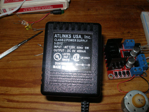
I'm playing around with the same L298N-based board as you, Ralphxyz. So far I've had very little luck, but one thing that I did notice (actually when I was testing earlier with a SN754410 IC, but I think the principle is basically the same): I had LEDs hooked up to each of the four inputs (A, /A, B, /B). I was trying to drive the motor with the usual pattern of A|B, A|/B, /A|/B, /A|B, so at any one time 2 of 4 LEDs should be lit up. What I found was that ALL 4 LEDs were lit up ALL the time. My suspicion is that I need to put diodes between each of the 4 digital I/O lines and the 4 pins on the IC (I really should do that any way, to protect the AVR chip). The ~.6V diode drop shouldn't really matter in the scheme of things, it should still register as a digital HIGH signal with the L298N, I think. I'm about to head home and play around some more, and see where I get to. NOTE: I have the stepper-controller board hooked up to a desk power-supply. I find with the Enable lines low that the current draw is (predictably) ~0mA, with the Enable lines high it is ~10-30mA (and there is a very slight but noticable torque increase on the stepper shaft) and if I plug A,/A,B,/B pins directly to GND or +5V I can (in some configurations) draw ~130mA and the stepper shaft is very hard to turn by hand. So yes.. the theory of driving a stepper motor is fairly simple, but so far I've been unable to get it to actually step/rotate as I would like. There's a long way to go to building my desktop CNC machine :) P.S. were you able to get the motor to step at all (even just a single step) by driving the input pins (A,/A,B,/B) high/low directly from the GND/+5V rails? I have been able to do this, but with a 1.8 degree step, it's really barely noticeable! |
|
June 19, 2012 by JamesFysh |
OK, so I've hooked it all up as such: OUT1, OUT2 go to either side of one of the stepper motor coils, and OUT3, OUT4 go to either side of the other coil. +12V to the +12V pin, GND on the stepper-motor control board is connected to GND on the AVR power-supply. I've had limited success, so far. With the following code: I am able to get the motor to kind-of rotate. I suspect I might need to tweak the delay-times, at least to improve this. Note: If you have a 2-channel oscilloscope, hook coil 1 up to one channel, coil 2 up to the other. If you then rotate the stepper-motor by hand, you'll see some really nice, smooth sine-waves (with one leading the other by 90 degrees, I believe?). I guess the lack of smooth rotational motion stems from the really poor approximation of 4 bits to two smooth, independent sine-waves? Anyway, progress! And I think the diodes do help.. ... Just tinkering before I post. With an 8ms delay between pin-changes (not 7, not 9.. only 8!) I get really quite smooth rotation with the above code. Sometimes it reverses direction for a bit, and occasionally it stalls, but generally very smooth. So far other values (2, 4, 5, 7, 9, 10 that I've tried so far) all just cause the motor to lock up / "flicker" back and fourth. Of course, the value of 8ms is probably right for the stepper motor I have - your mileage may vary. |
|
June 20, 2012 by JamesFysh |
Hey RalphXyz, did you end up getting your code to compile? Any luck getting the stepper to work, yet? |
|
June 21, 2012 by Ralphxyz
|
Hi JamesFysh, I just spent most of the past couple of days in the Emergency room. I had a kidney stone that I could not pass, damm did that hurt. I got my code to compile, that I hard coded the header (PORTB) pin changes, but the motor does not turn I feel a very weak click on each step. After I added the ), thanks to Rick, my code using #define for the PORTB values compiles, Thanks Again Rick. I have not tried to run the motor yet with the #define code!! How are you doing? I was hoping to be able to vary the speed with the step timing but I was looking for more that 8ms vs 10ms differences, we will have to see. Ralph |
|
June 21, 2012 by Ralphxyz
|
JamesFysh, is this the controller you have?
Here is the schematic:
The diodes are included so I do not see why you might have needed to add diodes. Do you have your motor running? Ralph |
|
June 21, 2012 by JamesFysh |
Ouch! That sounds painful! Hope you're feeling better now. Yes, I have that exact same controller. Ebay is a wonderful thing :) I couldn't find L298N chips (i.e. just the plain old chip by itself) for as low of a price as that board. And it even arrived in about a week - usually when I buy the odd component from Hongkong/china on Ebay it's between 2-3 weeks shipping. So, I thought I would tinker with this a bit more this morning before work. Interestingly, my previous code (with 8ms delay between steps) did NOT work any more - the motor is now doing what it does with other delay periods; vibrating or clicking back and fourth a step. After much more tinkering (different delays, driving the 4 input pins high/low in many different orders) I still didn't get it to really turn again! These things are tricky. I did find that if I use a ~20uSec delay that it acts as a really crude speaker :) Something tells me that if I drive the pins in the right order, the delay length shouldn't actually make much difference - i.e. it will alter the speed of rotation but not whether the motor actually turns or not. So I still suspect that I'm getting the sequence wrong. By the way, I found a really good intro to stepper motors (a PDF file) here. At the bottom of page 4, it has the exitation sequences for driving a stepper motor. It looks like the drive-mode suggested for this controller is the "wave drive" mode. This is the mode in which I actually got the stepper to rotate the other day. I've tried full-step mode with no success. I'll give the half-step mode a shot tonight when I get home. I also tried with and without diodes - no discernable difference. Note that the 8x M7 SMD diodes appear to be sitting between either +12V and the output pins or GND and the output pins - there are no diodes between IN1/2/3/4 and the IC pins. However, based on the block diagram in the datasheet, it seems like IN1/2/3/4 are connected to AND gates which are in turn connected only to the Base pin of transistors. I believe that neither the inputs to the AND gate nor the base node of a transistor should ever SOURCE current, only sink it so diodes on the input are probably redundant. I still don't mind including them, however - I'd prefer to destroy some diodes than half the pins on one of the ports of the AVR, if anything should go wrong :) So I have some questions for someone with more experience with stepper motors.. Usually when dealing with stepper motors, it seems like each coil is given a letter-designation. So for a motor with 4 wires (= 2 coils), you would have coils A and B, and the 4 wires would be labelled A, /A, B, /B.
Ralph, I think many of the times I've been testing this, I have had A and /A as pin 0 and 1 of PORT D, but in the code I have treated pin 1 as B, then pin 2 as /A and pin 3 as /B, when the physical wiring would be A, /A, B, /B (i.e. /A and B are switched). However, I have definitely tested after switching the middle two inputs around (either physically or in code) and still haven't had much luck. Further, I don't necessarily know which of each pair of wires from the stepper represents A or /A, so it's possible I have also switched either A and /A or B and /B during much of my testing. Tonight I will make a concerted effort to identify which wire from the stepper corresponds with which side of each coil, and that it's wired up all the way through, correctly so that when I think I'm driving A HIGH and /A LOW in code, that's actually what's happening with the stepper. I'll then try each of the three drive-modes from that PDF (Wave, Normal-step and Half-step) again. |
|
June 21, 2012 by Ralphxyz
|
JamesFysh, Your code (from 2 days 16 hours ago): int main() { } matches the truth table But what about the "return to step1" column? What does that mean? I am also wondering if a L297N preprocessor chip is required. Rick has used the L298N with the L297N. So far I can only get a weak click off the motor no rotation. I sent a email to the supplier asking if there was any Arduino code but have not heard back from them. Thanks, I am feeling much better and that was painful, the only prevention is to drink tons of water everyday. With this heat on the east coast I'll spend most of the day inside so I'll keep trying things but between what you have done and I have done I am running out of things to do. Guess I'll re-re-read the stepper motor tutorials. Ralph |
|
June 21, 2012 by JamesFysh |
Hey Ralph, I think the "return to step1" means just that - if you want to keep rotating the drive-shaft, go back to step 1, then 2, 3, 4, 1, ... forever. Did you try hooking the 4 wires of the stepper up to an oscilloscope? I.e. A and /A to the first scope probe + grounding alligator clip, B and /B to the second scope probe + grounding alligator clip, and then rotating the shaft by hand? When I did this, I saw a sine-wave on each channel, offset by 90 degrees from eachother. The 0b1110, 0b1101, 0b1011, 0b0111 pattern is (in my mind) a very rough approximation of this waveform, and it makes sense that if you re-create this waveform over these wires that the shaft will rotate in order to comply with the waveform (i.e. the reverse of manually rotating the shaft and monitoring the waveform). I definitely like the idea of using the L297 chip alongside the L298N - it looks like it takes care of all of this complexity for you, and presents an even simpler interface (1 pin to control CW/CCW, another to control whether the motor should be rotating or not).. how easy! And the fact that it takes the output of the current-sense pins into consideration is nice too (My circuits to date completely disregard any feedback from the L298N, and just drive IN1/2/3/4 LOW/HIGH as I see fit). One thing you keep mentioning is that you're only getting a very weak click from the stepper.. I guess I have a few questions
Lastly, some picures - Sadly I don't think they add very much, but hey.. pictures are cool :)
Note the mess of wires - this is why I'm not 100% confident that Port D, pin 0 definitely matches up with IN1, or that IN1 definitely matches up with A (and likewise for pin1, IN2 and /A, and also B, /B). I guess getting the exitation sequence correct is pretty crucial to being successful. Must be more diligent when I test again :) |
|
June 21, 2012 by Ralphxyz
|
I'll bet my problem is that I do not have a common ground!! I'll try that tomorrow. Thanks, darn I've been caught by that before. Ralph |
|
June 22, 2012 by sask55 |
JamesFysh I do have some experience controlling stepper motor with a completely different controller chip. there a couple of points that I believe are somewhat different then your interpretation of the A,/A,B,/B designation. As you have said, with a bipolar motor there will be four wires that are connected to two independent coils. • A and /A refer to the two wires on either side of 1 coil, right? So there should be a measurable resistance between A and /A, but between A and B (or /B) should be open-circuit? this statement is true. I believe the A and the /A does not represent the two wires on the A coil but rather is a sequencing order for the polarity of the A coil. As you have said the H-bridge circuitry will allow either side of either coil to be set to ground or to +V. That capability is necessary to reverse or flip the current flow thru the coils and therefore reverse the polarity of the magnetic field of the coil. The coil energizing sequence A B /A /B is indicating the order that the coils should be powered to produce rotation. first A----- energize coil A next B -----energize coil B next /A ----energize coil A with the opposite polarity that it was before finally /B----- energize coil B with the opposite polarity that it was before start again with A I believe that by swapping the wires on either coil will result in the direction of motor travel reversing direction if you go thru the same sequence. because essentially all that you would be doing is changing A to /A and /A to A by swapping the wires on A coil. I might suggest that you do a simple test to confirm that the motor controller board is performing as expected. I would eliminating the Nerdkit MCU from the setup circuit until I was satisfied that the controller board is working as I expect it to. I would disable the onboard 5V logic power supply on the controller. Connect the Nerdkit 5V power rail to the +5power on the controller board. Connect the Nerkit GND rail to the power GND on the controller board. Use four jumper wires to set the step 1 bit nibble on the controller input pins. ie connect IN1 to GND and ,IN2,IN3 , IN4 to the nerdkit 5V power rail. Now use a volt meter to test the state of both of the coils note the polarity of any coil that is active. Do the same process for the other three steps by setting the input pin state on the controller. By going true this test you can determine if indeed the controller is producing a output sequence A,B,/A,/B when it is input with a sequence step1,step2,step3,step4 . If it is the problem is in setting the input pin states with the MCU if it is not the problem is with the controller board or the understanding of what input is expected. an interesting problem, it just seams like it should be working Darryl |
|
June 22, 2012 by Ralphxyz
|
I am now using a common ground and getting a more solid click but no rotation. Darryl I did your test and the controller board appears to be working except I never see GND on the low pin I see +.85V. On the hi pins I see approx +12V as expected. Ralph |
|
June 22, 2012 by Ralphxyz
|
I used a longer delay and monitored the voltages with the mcu in place. Now I see approx 12V on three pins (output) and .85V on one pin but it is always the same pin that is low. Here is my latest code attempt: For some reason it is not stepping through the steps. Also all I see on the LCD for LRSTEPx is: Constantly Ralph |
|
June 22, 2012 by JamesFysh |
Yep, you're ORing each value onto the existing value - this is not what you want. Since you've defined each of LRSTEP1..4 as the entire value for the port, your code should probably read (Note the use of the = operator, not the |= operator). Remember, |= can ONLY enable bits that weren't already enabled, it cannot set any bit LOW, so you will just end up setting all bits high, if all you do is OR PORTB with different values. Also, for the logging, you have LRSTEP1 logged twice. Your last fprintf_P should probably read LRSTEP4. I played around with my setup a bit more, but didn't get any further. I did switch the wiring on OUT3/OUT4 (I think I had the wires around the wrong way) and tried a few more permutations on the code, but I'm still finding it just clicking back and fourth. Depressing :( |
|
June 22, 2012 by sask55 |
That sound good, so just to be clear if you are testing the voltage across the two output connectors for output A and output B we are seeing a sequence something like. output A step two = no voltage step three = -12volts step four = no voltage output B step one = no voltage step two = +12 V step three = no voltage step four = -12 volts if this is the case then the controller board does appear to be working. I would now place a small piece of tape to the shaft of the motor and manually cycle thru a couple of sequences of step one, two, three and four. You should be able to see the very small amount of rotation of the shaft with each step as the end of the tape moves around. I have to go to work. I will think about this a bit. On a slightly different note I think I may have misinterpreted the function of the on board +5 volt power connection on the controller chip. It appears that this is actually intended as a +5 volt output or source of power for external logic. You could enable that source and use it to power the Nerdkit board in that way eliminate the need for two power supplies. Darryl |
|
June 22, 2012 by Ralphxyz
|
JamesFysh, I am O'ring each value because I do not want to effect all of PORTB only the 2nd, third, forth and fifth bit the other bits might/will be used for buttons so I do not want to do a PORTB assignment I am kinda rusty on doing pin assignments this was my best guess but I know I do not want to do a assignment as that changes the whole PORT. Darryl, No that is not what I am seeing!! I am seeing: I never see -12v!! What I am seeing matches the truth table except for the 0.85v which should be 0v or possible common ground or at least to my limited understanding. Ralph |
|
June 22, 2012 by sask55 |
Ralph I am looking for is the voltage readings BETWEEN the two connectors on each output set. The VOM will be in parallel with the coil. We are attempting to measure the actual voltage polarity applied too each coil for each step .It looks like you are measuring the voltage level from one side of the output to ground. If I assume that the reading on your table are from the four output connector then I can see what the voltage will read across the coils. from your table step1 int1 to int2 is ~ +11Volts and int3 to int4 is 0 volts step 2 int1 to int2 is ~ -11volts and int3 to int 4 is 0 volts step 3 int1 to int2 is 0volts and int3 to int4 is ~ +11 volts step 4 int1 to int2 is 0 volts and int3 to int4 is ~ -11volts your controller chip is working as expected I do not have the time right now to read all that is in this thread so I may be repeating here. I think JamesFysh has the right idea about you code. For the four LSB you will have to set the bits that are intended to be high as well as clear the bits that are intended to be low for each step. You are correct in you do not have to make any changes to the bits that are not used to set the controller inputs, but you will need to set or clear all four of the LSB for each step to insure they are correct. Each time you change to a different step there are two bits that will be flipped one will be set another one is cleared you must be sure both changes are made. since the order of steps may be either up or down depending on the rotational direction it will be simplest to just set or clear all four LSB to the correct level for each step with no regard to the last step. Darryl |
|
June 22, 2012 by Ralphxyz
|
Wow sask55, how in the world did you get this:
from my table? ??????????????? I have no -11volts or any 0 volts. And what the heck does ~+11Volts and ~-11volts mean?? The ~ is what throws me. And then:
It looks like you are saying to set AND clear all four LSB to the correct level that is something like this: Is that what you are saying? Ralph |
|
June 22, 2012 by Ralphxyz
|
With my meter parallel to the coils I get: OUT1 1.3mv OUT2 10.32V Running my code with the "clear" setting PORTB &=~LRSTEP1..4; and LRSTEP1..4 hard coded LRSTEP1 = 14 etc. The motor does a strong click and freezes, when powered I can not turn the shaft. Ralph |
|
June 23, 2012 by Rick_S
|
Ralph, he may have meant approximately with the tilde character. Even though the tilde is used in C, in other writing it is commonly used to mean approximately. I was trying to find my code I used to drive a stepper the other day when I was reading this thread. For the life of me I don't know what I did with my stepper code. I know I played around with the L298 with and without the L297 to drive small (Old 5-1/4" floppy drive) steppers. I'll look again and see if I can find it. |
|
June 23, 2012 by sask55 |
Ralph What I am trying to find is what coil is active and what the polarity of the current in each step. Sorry about the use of the~ I was thinking approximately I see now that it is easily confused with NOT. Anyway 10volts or 12 volts is not really important it is still a considerable amount of driving voltage. The coil polarity is important. Is the current being flipped, turned around if you like? When is each coil not being driven at all ie the driving voltage on the coil is near zero? PORTB = ((PORTB |15) & ~1) will first maintain the 4 MSB at their present values and set the 4 LSB's to 1, the result of that is then AND ed with (NOT 1) (11111110). we should get (????1110). If I understand your table correctly and INT1 - INT2 are coil A and INT3- INT4 ar coil B then. the controller is working in that it is activating the coils and flipping the current flow. As strange as it sounds the activation sequence step1,step2,step3, step4 is completely wrong. There is no way we can expect to produce a turning force when going from step 1 to 2 or from 3 to 4 as all that is happening is the ciol is reversed in polarity. step 1,2,3,4 is A,/A,B,/B this is not a viable rotational sequence. I would try and implement a wave sequence as this is common sequence. A,B,/A,/B. As bizarre as this sounds you have nothing to lose try step1, step3, step2, step4 and repeat. I am betting it will work well. Darryl |
|
June 23, 2012 by Ralphxyz
|
Darryl, thanks once again. It is so strange that some (most) of the things you are saying are what I intuitively had thought (from my readings) but were contradicted by the truth table supplied by the controller seller on ebay who I assumed knew more than I. I have been trying to communicate with the seller and I find that they are totally ignorant. They even have an arduino reference in the controllers title but they have no idea why, or even what it means, Buyer Beware!!
I have done some previous stepper motor work, which I got to work thanks to Rick_S's help and from that I thought the truth table had to be wrong, thanks for clearing that up for me. I have so much going on I didn't want to have to put a lot of time into getting a stepper motor to work so I went with the ebay controller I would have been just as well off to just purchased a L298N and L297N and put it together myself (with Rick_S's help of course). I want to do a write up for the Nerdkit Community Library so once I get this controller working I will still get a L297N to play with that. Adding the L297N looks like an interesting addition I am not sure what it actually does or how it works but it does offer some interesting options. So let me change my code and I'll be back. Ralph |
|
June 23, 2012 by Ralphxyz
|
Darryl your suggested changes do not work. Or at least my implementation of your suggested changes do not work. Here is my current code: Interesting note, this code produces a single click in the motor and then the rotor freezes. Using my modified code: I get a continuous enthusiastic clicking like it is really trying!! It seems to like the clear statements. JamesFysh how are you doing? What does your current code look like? Yeah Rick_S, find your L298N/L297N code and hopefully a schematic of your wiring I am going to need it. Ralph |
|
June 23, 2012 by mcguinnessdr |
I am leaving Sunday for a week and was going to order some parts before I leave so they are here when I get back. I was thinking about getting the controller you are using, but it appears like it's not working. Would I be better off purchasing an L298N, L297, and the other necessary components? If I did, what other components would I need? Hopefully since we are both working on the same problem, we can figure it out together (if you haven't already got it working by the time I get back). |
|
June 23, 2012 by Ralphxyz
|
mcguinnessdr, I would go with the L298N/L297N combination. The L298N datasheet has a good schematic of the L297N and L298N together. Also Rick_S "has" had the L297N/L298N working so it should be pretty straight forward on getting it working. The L298N/L297N combination also gives a lot of option for control and other things. You can breadboard the L298N/L297N and eventually maybe we can make a PCB. The PCB fab that Rick_S is using is very reasonable and we could do a joint purchase. So definitely I would go with the L298N/L297N, we will get the controller that JamesFysh and I have working but I like the options of the 298N/L297N. Ralph |
|
June 23, 2012 by Rick_S
|
If I have time tomorrow, I may pull out my 297/298 ic's and play with them. No time today though, got a date with the wife tonight. I don't have actual boards with the IC's on them though, I just have the raw chips. I had to make an adapter board for the L298N because of it's offset pin package. I really wish I could find my stepper stuff. I'm wondering if I programmed it on a different computer. Anyway, the purpose for the L297 is to eliminate all the stepping logic from your program. All you have to do is set a direction pin, and send a single pulse to make the stepper run. The L297N creates the step patterns for you. I did find my youtube video of me driving a stepper with the 2N7000 transistors but I can't even find that code... Frustrating. |
|
June 23, 2012 by mcguinnessdr |
If I just got a L298N without the L297, then I could just control it with 4 pins from the MCU to control the stepping, right? I still need 8 diodes like those indicated in the schematic on the L298 datasheet showing it connected to the L297, but I wouldn't need all the capacitors resistors it shows, right? This seems like it should be so simple, bit it's very complicated. |
|
June 23, 2012 by Ralphxyz
|
Ok I hooked up some LED's to see what was happening!! Using this code: and these settings for LRSTEPx Energizing 2 coils at a time makes sense. You might say energizing 1/2 coil at a time makes sense. So with the above I get: The motor does not turn just click aggressively!! Do I have to do a init at the start? Of course I am trying things as I am writing this and now using this code: I get: Now what do I need to do with my code to get OUT1 flashing? Ralph |
|
June 23, 2012 by sask55 |
make sure that connect IN1 to PB0 mcu pin 14 } |
|
June 23, 2012 by sask55 |
The only question is. In your table does the INT1 and INT2 mean the connections to one coil and INT3 and INT4 are the connections to the other coil? If so that is true then there is is NO CHANCE that the sequence order step1,step2,step3,step4 will work. Darryl |
|
June 23, 2012 by Ralphxyz
|
re : INT1 and INT2 That is INI1 and INI2. I have had problems attempting to use PB0 in the past. If I remember correctly something the bootloader does stops me from using it. But yes: This is how I have it wired!! This is why I started out using PB1, PB2, PB3 and PB4 instead of PB0, PB1, PB2, PB3. I switched when you were referencing LSB and MSB so I understood you did not see what I was (attempting) to do. Ralph |
|
June 23, 2012 by Ralphxyz
|
sask55, with your code: I get on my LEDs: OUTx being connections to the coils!! Darn, bad wiring on OUT1 it only makes contact if I hold in place. So using Sask55's code I get: Using my code I get: But the motor still does not turn!! Ralph |
|
June 23, 2012 by Ralphxyz
|
Ok!! I messed with the wiring more and have it running using sask55's code!! THANK YOU!! Strange I still have: But the motor is turning!! The motor now runs with my code also!! There appears to be a lot more torque with my code!! Ok I will be back with questions about using buttons to turn on and off the motors and lots of other things I am sure!! Ralph |
|
June 23, 2012 by mcguinnessdr |
Glad to hear you got it working!!! What was the problem, was a wire loose, or just in the wrong place? I think I'll get this controller then since it's cheaper than the l298/l297 combo. |
|
June 23, 2012 by Ralphxyz
|
There was a lose wire which was why I was getting OUT1 off. When I saw the off, which I knew should not be, I started testing every connection and actually found two that either not connecting or just barely occasionally! So this controller works and we have working code. I will re post my working code here and I will do a Nerdkits community Library. I have tested delays between 2ms and 1000ms which work! Now I need to control the speed using a potentiometer/joystick. Ralph |
|
June 24, 2012 by sask55 |
Great - glad you have the motor turning. I have never used that chip, but have used a couple of other controller chips. The tosheba chip that I am using has considerably more features and functionality. The chip you are using is more basic and simpler to use. They seem like a good deal I think l will order a couple just to have on hand. I am still very curious about what the coil activation sequence is being implemented on this chip with the step1, step2,step3,step4 input sequence. I think I will make the simple test that I suggested to you to determine with 100% certainty which coil is on and its polarity for each of the four input states. With that bit of info it is simple to see what activation sequence is being applied to to motor coils. It is clear that I misinterpreted the reading on your table, I can not determine which of your readings belongs to each of the two coil output connectors . I would suggest that you consider changing the locations of your LEDs. If you placed your four LEDs across the output connectors, in parrell to the two coils you would be getting more useful information. By having two LEDs with their current limiting resistors on each output, with one LED orientated in each direction you could see at an instant which coil was active and what the polariy of the coil was ie + or -. That information is what is required to establish what sequence is being applied to the motor. Darryl |
|
June 24, 2012 by Ralphxyz
|
Hi Darryl,
Yes this controller is limited essentially on/off. I think when used in conjunction with the L297N you get more functionality. PWM motor speed control, single pin direction change etc. Thanks once again for all of your help. Hey JamesFysh, how are you doing? Anything we can do to help? Ralph |
|
June 24, 2012 by Ralphxyz
|
Darryl, this is the start to my Nerdkits Community Library Stepper Motor article. See if I answer your question about "coil activation sequence". Please let me know if I need anything further. In fact as this article will be in the Library please feel free to add to/enhance it, everybody is encouraged to contribute. Stepper Motor Wiring: Black--A+ , Green--A- , Red--B+ , Blue--B- Controller Wiring:
Controller INPUT: ENA | INI1 | INI2 | INI3 | INI4 | ENB (ENA and ENB = ENABLE) Motor/Controller Wiring: Note: A- and B- can also be designated with /A and /B In summary a Bipolar Stepper Motor has two coils, to get rotation the coils have to be energised. Essentially 1/2 (of each coil) is energized with + Voltage the other half of the coils is at Ground or possible - Voltage. In this mode both coils are energized at the same time. Stepping the motor would be as follows: From my code: Read from right to left, LSB to the right! I assume the above is a "Full Step" mode. I believe there is a 1/2 Step mode and a Wave mode how would I use these? So this inconjuction with all of the Stepper Motor articles What is missing what more can/should I do? My full code will be included with the Library article. Ralph |
|
June 24, 2012 by sask55 |
Hi Ralph Actually in a bi-polar motor there are two coils as you said. Each coil has two wires, one connected to each end of the coil. Either of the coils can be only be in one of three states OFF- no current flow thru the coil, this is the case when both ends of the coil are at the same voltage level ON- current is flowing thru the coil. This is the case when one end of the coil has a voltage level that is higher than the other end. That difference in voltage drives the current from the high voltage end to the lower voltage end. For a bi-polar motor drive there are two complety different posiblities for the ON state. The current can flow in ether direction thru the coil. At times the current will flow from left to right when the controller makes the left end of the coil have a voltage higher then the right end. At other times the current will flow thru that same coil in the opposite direction, when the controller make the right end of the coil have a voltage higher then the left. The current flow direction can be thought of as positive and negative or zero, three completely different states. The motor rotation is produced by setting up a sequence or pattern of coil activation states in the motor. Only a few patterns will produce a rotation most will result in a vibration of the motor shaft with no turning force. There have been a number of way to note or discribe the sequence that will work. A very common notation is to us the letter A to represent current flow in one of the coils, and then use the notaion /A or A under a line to represent current flow in the opposite direction in the same coil. Current flow in the other coil is noted as B and /B which will mean current flow in the second coil and negative current flow (current in the opposite direction) in that same coil. There are a few coil activation sequences that will produce rotational force. One that is comonly used is often refered to as the wave sequence. Using the notaion disused above the wave sequence is A,B,/A,/B. What this notation is saying is one way to get rotation in a bi polar stepper is to activate the coils in this order. First put power to one coil A, then for the next step put power to the other coil B, then for the next step put power to the first coil but in the opposite direction that it was in step1 then for step 4 put power to the second coil but in the opposite dirrention to what it was in step two. By repeating this patern over and over you should produce rotational force in the motor. I think your explenation is not quite correct. I know I often make a lot of spelling and typing error but I think something along this line is a better expelenation of big polar motor drive. Darryl |
|
June 24, 2012 by JamesFysh |
Hey Ralph, glad you got it working! I spent most of the weekend at a friends house, and I'm heading interstate for the next few days for work, so I probably wont get a chance to look at this again pretty much until next weekend. I still haven't gotten what I consider to be a "reliable" rotational force from the motor - when it was rotating haphazardly the other day, I think I obviously still had some error in the exitation sequence I was using (or the wiring .. same thing really, I guess :). I will tear it all down and start again from scratch - I might try to make it rotate manually (by just plugging the 4 wires on the stepper directly into GND/+12V rails on a breadboard) as a start, as I haven't really had much luck with that in the past either. I'm very aware that if I get the two wires for one of the coils switched around (as in, red into OUT3 and yellow into OUT4 when it should be red -> OUT4, yellow -> OUT3) then I'm unlikely to have much success (unless I change the excitation sequence in software), and I still suspect that that is what has been wrong up till now. |
|
June 24, 2012 by sask55 |
Ralph I might add one more thing. I imagine that the L298N- controller is producing a full step drive sequence rather then the wave drive. In a full step the controller will be energizing both coils all the time to give much better torque. The full step sequence is AB,/AB,/A/B,A/B you could easily verify that. there is also half stepping. Mirco stepping is another story that involves adjusting the voltages to the coils in a longer sequence. Darryl |
|
June 24, 2012 by Ralphxyz
|
Wow Darryl, I am really apparently missing something. I "think" your explanation is exactly what I illustrated.
Isn't that exactly.. Oh wow I just looked at my prior posting and none of the code examples are showing. So you could not see what I was saying. this stupid Markdown forum really sucks. All of those big blank areas should be filled with code and literal text! I will try reposting, if that does not work, we still get blanks inplace of code or literal text I will post in segments which will be a pain. I believe I am illustrating exactly what you are saying. JamesFysh, I will re-post my working code you can just connect everything as i have outlined here and run my code and it "should" work you do not need to do anything more. See my next post. Ralph |
|
June 24, 2012 by Ralphxyz
|
Here is a re-post of my prior post: Everything is here in Preview so let's see what happens. Darryl, this is the start to my Nerdkits Community Library Stepper Motor article. See if I answer your question about "coil activation sequence". Please let me know if I need anything further. In fact as this article will be in the Library please feel free to add to/enhance it, everybody is encouraged to contribute. Stepper Motor Wiring: Black--A+ , Green--A- , Red--B+ , Blue--B- Controller Wiring:
Controller INPUT: ENA | INI1 | INI2 | INI3 | INI4 | ENB (ENA and ENB = ENABLE) Motor/Controller Wiring: Note: A- and B- can also be designated with /A and /B In summary a Bipolar Stepper Motor has two coils, to get rotation the coils have to be energised. Essentially 1/2 (of each coil) is energized with + Voltage the other half of the coils is at Ground or possible - Voltage. In this mode both coils are energized at the same time. Stepping the motor would be as follows: From my code: Read from right to left, LSB to the right! I assume the above is a "Full Step" mode. I believe there is a 1/2 Step mode and a Wave mode how would I use these? So this inconjuction with all of the Stepper Motor articles What is missing what more can/should I do? My full code will be included with the Library article. Ralph |
|
June 24, 2012 by Ralphxyz
|
Darryl, I am producing: Why cannot you see this?? Also this is exactly what my LED arrangement shows. What more could I be asking of the LED's? Ralph |
|
June 24, 2012 by sask55 |
Hi JamesFysh The only thing that is important on the output side is that you make sure that you have the two wire that are connected to each of the coils paired up. Make sure that OUTPUT A has both wires from the same coil and that OUTPUT B has both wires from the other coil. As you said earlier you can be certain that two wires are from the same coil,if you can measure a relatively small amount of resistance between then. Wires from the other coil should be an open circuit. Changing or swapping the wires on one of the coils will only result in the motor turning the opposite direction when the activation sequence is sent by the controller. Think of it this way The full step sequence is AB then /AB then /A/B then A/B Now if I swap the connections to the A coil then A becomes /A and /A become A in the hardware. So if we swap the A and the /A in the sequence we get what may appear to be a different sequence /AB then AB then A/B then /A/B. But if we start at the same place say AB in both sequences the original sequence reading to the right is the same as the new sequence read to the left. I am not sure you will follow this but believe me swapping the two wire from one of the coils just reverses the direction of rotation of the motor nothing else. Darryl |
|
June 24, 2012 by JamesFysh |
Darryl, If both could are always on, I agree. Using the original sequence where only one coil is active at a time (as I was doing before), I'm not so sure. remember the original pattern was: 0b1110, 0b1101, 0b1011, 0b0111. anyway, time to get on a plane and forget all of this for a few days... Maybe |
|
June 24, 2012 by sask55 |
Ralph “Essentially 1/2 (of each coil) is energized with + Voltage the other half of the coils is at Ground or possible - Voltage.” I did not understand what you where saying here. I was thinking you cannot possibly activate 1/2 a coil. I think now you are saying the same thing I just did not read it that way. The name BI polar says it all it is one direction or the other, one polarity or the other. “Step1 = 0101 = (OUT4 -) (OUT3 +) (OUT2 -) (OUT1 +) = (-12v) (+12v) (-12v) (+12v)” I am still a little confused about the -12V here. What are you measuring this voltage against? Are these level not 0volts to ground. Which I realize is -12 volts form the high voltage level but the other end of the coil may not always be at the high voltage level. I may be missing something but I think the -12Volts is only appropriate when measuring the voltage across the coil. so one reading on each coil for each step. The order of the sequence is correct it is just kind of obscured, at least to me, somewhat with unnecessary data and readings. Part of my idea to simplify things may come from my playing around with motor controllers capable of micro stepping. I realize that is not the case here but with micro stepping the coil activation voltages are both changing by a small amount with each step. I was troubleshooting a controller by measuring these voltage changes. I found it is just more direct to measure the coil activation voltage, then to worry about if the high level is coming down or the low level is coming up as the voltage across the coil is being lowered. I see now that with this controller there is a direct logical link between the input connections and the output connections. This is not the case with the other two controllers I have used. With the other controllers I would select what type of sequence I would like ie wave, full , half or micro stepping, the controller does the actual activation and sequencing. I found the table in the controller documentation misleading. I think the use of the words step1,step 2 lead me to think that this is the order the steps should be taken. But; no you have it correct, in order to get both coils to active at the same time to achieve full or half stepping you have to combine a couple of the so called steps into one. Then you have to determine the order that you need to get rotation. You can easily implement any of the other rotational sequences by just activating the appropriate coils with the correct polarity in your code sequence. Half stepping is a 8 step sequence other then that just put the correct input nibble on the input connectors and you should get the correct output on the coils. Rather then the truth table in the documentation I think it would be more clear and understandable to just state that each of the input connectors is in direct control of one of the output connectors and just set or clear the appropriate bits to get the desired output As far as my suggestion about the placement of the LCDs it really makes no difference you will get the same data. It just seams more direct to me, you would get a direct indication of what coil is in what state no interpretation is required. You could label the four LCDs as A, /A, B, /B if you like, at a glance you could see the state of the two coils ie positive current ,negative current , no current for each coil Anyway I am not trying to make you angry I just feel there is a more direct approach to measure or displaying the relevant factors here. And to be honest I never took a close enough look at your last table to really understand what you are saying. After looking it over again it is all their. I guess I should not be so much in a hurry trying to do this stuff and other things at the sametime. Carry on you are doing a good job. Darryl |
|
June 25, 2012 by Ralphxyz
|
Thanks Darryl, my post was just a start and I was looking for feedback, you have helped simplify it for me thank you. You have to remember I do not know what I am talking about, just what I am experiencing as we go along. JamesFysh,
The truth table had: Which Sask55 has pretty well demonstrated could not work so just forget about using anything from the vendor besides the wiring guide!! The working pattern to use is: Which now from Sask55 patient (bless your heart) instruction is so logical. Now just looking at 0101 I can see exactly what he is saying: Obviously bit one is energized bit 2 is at ground bit three is energized bit 4 is at ground. In one of my tables I had used -12V this should be GND not -12V. Wow what a great thread I hope others find it as informative as I have. This will continue on I need to: And who knows what else!! Of course I would also like to add a Sparkfun Tilt Sensor and it would be really cool to finally get my I2C Compass module working. One of my applications of this Pan/Tilt is for a Solar Sun tracker. So I also need to add another motor. Ralph |
|
June 25, 2012 by sask55 |
JamesFysh "remember the original pattern was: 0b1110, 0b1101, 0b1011, 0b0111" I believe Ralph has found that this original pattern is not a viable rotational pattern. The truth table is misleading (I think it is). It is not actually indicating an order of steps as it implies. It is just showing the relationship between input connectors and output connectors. It is saying the output to any individual output connector is inverse to the corresponding input pin. Set the input pin high and the corresponding output will be low, clear an input pin to low and the corresponding output will be high. As I understand it Ralph is driving a motor with this sequence FULL STEPPING If a person wished to do half stepping or wave stepping they would require the use of these four input states as well, BUT NOT IN THIS ORDER. The correct order for each sequence is listed on the web page that Ralph has linked. I think of it as the left most two bits control the current flow thru the A coil and the right most two bits control the current flow thru the B coil. With these eight input conditions you can energize the coils to any one of the eight states used for full, half or wave sequences. All that remains is to write a code to successively place the inputs on the chip in the correct order as Ralph has done for full stepping. Darryl |
|
June 25, 2012 by Ralphxyz
|
Darryl, re:
Everything I have done references coil A as the right two bits and coil B as the left two!! I will play around with half stepping and wave stepping. Now you lost me:
Which web page link did I use for order sequence? Thanks again, Ralph |
|
June 25, 2012 by Ralphxyz
|
Here is my latest working code: This is for Clockwise rotation "FULL STEP" on my motor: With my code: And yes, I down loaded and compiled my code, so no one should have any problems getting this far which is just a start. Ralph |
|
June 25, 2012 by sask55 |
Ralph Now that is crazy, I thought you linked this site on this thread, now I can’t locate a link to it on any thread. basics of steppers
The A coil on the right is fine it is just an arbitrary name. on a different point that you may be interested in. I don’t believe your code is doing what I think you may be intending it to do. I assume the you are attempting to maintain the bit values in the bits on PORTB that are not being used as input pins for the controller. That is keep whatever level the 4 MSBs are set at thru the control sequence without changing them. This code will not do the trick. This statement does maintain all the bits except the 2nd LSB that is cleared. This statement overwrites the entire portB byte to whatever the value of LRSTEP1 is, noting is maintained. PORTB is now 0b00000101 no matter what it was before this statement. This statement overwrites the entire portB byte to whatever the value of NOT(LRSTEP1) is, noting is maintained. PORTB is now 0b11111010 no matter what it was before the statement. . Consider defining the coil states and naming them with a recognizable name something like this. With the A coil on the right 2 LMS bits Use this code to produce a wave sequence in the motor. and maintain the 4 MBBs in PORTB wave sequence A,B,/A,/B Use this code to produce a full step sequence in the motor. and maintain the 4 MBBs in PORTB full step sequence AB, /AB, /A/B, A/B Use this code to produce a half step sequence in the motor. and maintain the 4 MBBs in PORTB half step sequence AB, B, /AB, /A, /A/B, /B, A/B, A use any ONE of these sets of code at one time. The reasoniing behind this code is to maintain the 4MSB on PORTB and change the 4 LSB to what we need. You dont need to use this code but you will have to use a AND and a OR to maintain the bits. |
|
June 26, 2012 by sask55 |
Ralph I noticed a few errors that I fixed from last post. section 9 Stepping Modes is the section that deals with the various drive mode sequences. Consider defining the coil states and naming them with a recognizable name something like this. With the A coil on the right 2 LMS bits Use this code to produce a wave sequence in the motor. and maintain the 4 MSBs in PORTB wave sequence A,B,/A,/B Use this code to produce a full step sequence in the motor. and maintain the 4 MSBs in PORTB full step sequence AB, /AB, /A/B, A/B Use this code to produce a half step sequence in the motor. and maintain the 4 MSBs in PORTB half step sequence AB, B, /AB, /A, /A/B, /B, A/B, A Use this code to produce a full step sequence IN THE OPOSITE DIRECTION in the motor. and maintain the 4 MSBs in PORTB FULL STEP IN OPPOSITE DIRECTION SEQUENCE AB, A/B, /A/B, /AB use any ONE of these sets of code at one time. |
|
June 26, 2012 by Ralphxyz
|
WOW Darryl, once again WOW. You have to remember I am not a programmer. I used to have a signature that said: I will get back to trying to use a mask to maintain the MSB (most significant bits). Thanks for the different MODES!! I will play around with them. Right now the "Full Step" mode I am using appears to produce the most torque. Using the clear statement that I did use PORTB &=~LRSTEPx; produces more torque than not using it. I could have used PORTB = 0; as I was no longer trying to maintain the MSB just trying to get something to work. Now for direction and speed buttons. I can see where using more advanced components like the L297N would help doing things besides run/don't run which is all the current controller appears to do. With the L297N I would have a single direction pin and PWM for speed control. Apparently one of the complaints about the L298N/L297N is that they are apparently power hogs compared to newer controller chips. Ralph |
|
June 26, 2012 by sask55 |
If you would like to use differnt pins on the MCU just let me know what pins you like. It is a quick adaptation to use any pins you like. We just have to change the values of a couple of the numbers. in the code. Datrryl |
|
June 26, 2012 by Ralphxyz
|
Fabulous, at the moment using PORTB and PB0, PB1, PB2 and PB3 seems to work fine. As long as PB0 works which as I have said I have had problems using in the past but so far it is working fine. I like your AB Aneg Bneg notation so I am trying to adapt that in my code. I just read your Stepper Link page. My head is kinda spinning, but I think we have a good basis for what I need from a stepper motor and a real nice Nerdkit Community Library article. I am working on control buttons now. I have some L297N components coming to give a different view/method of stepper control. Ralph |
|
June 26, 2012 by Ralphxyz
|
Darryl, I tried your three modes. Two of them work the third one doesn't! The half step mode: Just clicks the rotor does not turn! Ralph |
|
June 26, 2012 by sask55 |
Opps; I got the wrong coil state in line 20 on my last post. I cleaned it up a bit it is line 13 on the vertion below. //AB, B, /AB, /A, /A/B, /B, A/B, A Aneg_B is not correct, A_Bneg is the second last step of the half step sequence. so change that line to I think that should do it. The bit wise masking can be hard to get a handle on. As you know Setting and clearing individual bits in an 8 bit byte without affecting the other bits is often necessary when setting registers on a MCU. Here we are doing both setting and clearing on a byte in one statement it can be confusing. I could try to explain the above statement if you would like, but as your know often my explanations are not very clear. Darryl |
|
June 27, 2012 by Ralphxyz
|
I'll need a nice clear explanation for the Library article but for now let me work it out. Ralph |
|
June 27, 2012 by JamesFysh |
Phew, got it working with the drive pattern suggested several posts ago (A|B, NA|B, NA|NB, A|NB). I found a bug in my test code that's probably been there for quite a while. In fact, I can see it in the post I made above. I've physically hooked it up to use PORTD PD0-PD3, but for one or two assignments I'm setting PORTA, not PORTD!!! So when I hooked it up again and put some LEDs in place to test, I was finding that one of the pins was NEVER going HIGH. Anyway, it works! And with around 5ms between steps, it is drawing ~500mA @ 12V - If I grab the drive-shaft as hard as I can, I cannot stop it turning! Seems like a lot more torque than I was expecting it to deliver, so now I just need to think of something useful to do with it :) Thanks again for all the help, Ralph and Darryl - I probably would have given up and starting working on something else if not for this thread. Time to see if I can get it working with the TI chip (SN754410).. the pin-out looks roughly similar to the L298N, so it should be easy enough :) |
|
June 27, 2012 by sask55 |
Ralph He is an explanation of the code as I wrote it. This is certainly not the only way this could be done. There may be more elegant ways to code this, this is just one way to do it. I would expect that you will rewrite and possibly shorten this explanation a lot for your article. As most of it is general to bit wise operations and not specific to motor control in any way. You have four pins on PORTB as outputs to control the inputs on the controller. You will need to set some and clear some of these four bits for each step of the motor rotation. You would like to maintain the bit values of the remaining four bits in the PORTB register as we change the motor control bits. Currently you are using PB0,PB1,PB2and PB3 as the control pins for the motor controller chip. These four pins correspond to the four LSBs on the PORTB register. As you have it wired the 8 bits on the PORTB register byte can be thought of as. Where the ? indicates a bit value that in unknown that we wish to maintain, and the 4 LSBs are used to control the voltage applied to one end of each of the two coils on the motor. We know that the motor controller output in inversely related to the input. If PB3 is set high the corresponding controller output connector will pull that end of coil B low, if PB3 is set low he corresponding end of the B coil will be driven to near 12 Volts. By setting and clearing the appropriate bits on PORTB you can drive either coil with either polarity. You can send the current thru the coil in either direction. We are using A and /A notation to indicate what polarity we want for the A coil for any given motor step. The /A indicates the opposite polarity from A. in order to achieve the opposite polarity thru the A coil both PB0 and PB1 must be changed, and to change the polarity of the B coil both PB3 and PB4 must be changed. Arbitrarily picking any of the motor control steps as an example. using controller output AB as an example. where We want to leave the values in the four bits that we are not using as they are, while we put the appropriate set of values into the four bits that we are using on PORTB. To get A we set PB3 and clear PB2. To get B we set PB1 and clear PB0. Together we will set PB3, PB1 and clear PB2, PB0. First use OR to set all four bits, then use a AND to clear any bits that should be low to produce the correct output. In this way we know for certain what the value of all four bits are regardless of what they where on the last motor step. The compiler will complete the inner most parenthesis first. (PORTB | 15) is PORTB OR 15 using the characteristics of OR Why 15? Because 15 in binary is 00001111. This puts a value of 1 in each bit location we wish to set and a 0 in each bit location we are retaining.
so The four bits that are 0 in 15 are retained at their current value the four bits that are 1 in 15 are set in the resulting byte. The 15 byte is sometimes referred to as a bit mask. Then we need to clear the correct bits to output AB while retaining all the other bits. That is clear PB2 and PB0 while all the other bit remain as they are. The compiler will do the outer parenthesis (the AND) after the “or result” is determined & AB where AB is defined as NOT (5) using the characteristics of AND The compiler will take the “or result” AND it with AB and place the results of that operation back into the PORTB register. What does AB represent? It is defined as NOT (5). Why use NOT (5)? Because to achieve the output for the AB motor step we will need to clear the PB2 and the PB0 bits in the “or result” while retaining all the other bits as they are. NOT (5) is binary 11111010. It is a bit mask that will have a 0 bit for PB2 and PB0 locations and 1 for all the other bit locations. For any given motor controller output state we know which of the four MCU control pins must be cleared. Once those bits are cleared to 0 by the AND part of the statement we have the results we need because the other bits are already set to 1 by the OR part of the statement. The value 5 is the values of the PB2 plus PB0 bits expressed in decimal format (4+1 =5). The definition for each motor step is the NOT value of the decimal sum of the bits that are required to be cleared for that step. The NOT is used to flip all the bits in the definition, 5 becomes NOT 5 or 00000101 becomes 11111010 which is a perfect mask to clear only the PB2 and PB0 bits and retain the other bits with an AND. This may or may not be a clear Explanation,it is not short, it is about the best that I can do. Darryl |
|
June 27, 2012 by Ralphxyz
|
JamesFysh, why would you introduce a new syntax without any explanation? Your prior use of AB /AB /A/B A/B is what we have been using. Glad you have it running, this has been a good thread and it is not over yet. I have to do buttons for direction and speed next. Ralph |
|
June 27, 2012 by Ralphxyz
|
Darryl thank you, that is a great explanation. In reading it the first time I question some of your statements but I am sure you are correct and I just have not thought it through enough to understand exactly what you are saying. Things like: Now that I have to think about. But it looks great might just do a sub article. Now I need a couple of rainy days. Ralph |
|
June 27, 2012 by Ralphxyz
|
Darryl, nope your latest Half Step code still stalls the rotor no rotation!! Ralph |
|
June 27, 2012 by sask55 |
Ralph I did not make the change I just pointed out what should be done to fix the problem. I was thinking you may wish to see where the problem originated from, one step out of place in a eight step sequence.I kind of expected you to make the change after I pointed it out. In this post I have made the change to line 13 for you. Darryl |
|
June 28, 2012 by Ralphxyz
|
Sorry Darryl that's logical thanks, I am trying to squeeze this in so I just read through and tried it. I didn't think too much about what you were saying. I was going to work it through "when I had time". Ralph |
|
June 28, 2012 by Ralphxyz
|
Here is the working three mode code!! Ralph |
|
June 28, 2012 by JamesFysh |
Ralph, RE: The line Remember that the value of the DDRn register (where n is the Port you're dealing with) determines the direction of each pin for that port. A HIGH bit indicates the port is for output, a LOW bit indicates the port is for input. Since you're only ever using the low 4 pins on port B, the following code would be sufficient: Alternatively, you can use hexadecimal notation (other programmers likely feel more comfortable working with hex than binary, and it's more likely to compile with other compilers than the "0b" notation which I think is non-standard). If using hex, you would write: James |
|
June 28, 2012 by JamesFysh |
Ohh, and to be even more correct, you shouldn't necessarily assume bit 0 of DDRB corresponds to PB0. The following code is more correct: This ensures that, whatever PB0-3 are defined as, these exact 4 (physical) pins will be enabled by the code. You should likewise apply this approach to your other defines, such as AB, A_Bneg, etc.. they should be defined something like It's more tedious to write in the first place, but it is also more correct and more portable between e.g. other ATmega chips, and potentially other compilers. |
|
June 28, 2012 by Ralphxyz
|
Thanks JamesFysh, Actually I understand: a lot easier than: I still do not know why the MSB are hi. Why is (~(1<<PB0)|(1<<PB2)) the equivalent of 0b11111010? Ralph |
|
June 28, 2012 by JamesFysh |
The ~ operator, or NOT operator basically just flips every bit in a byte. If you were to set a byte as such; The byte value would be 5, or 0b00000101. If you were to use the NOT operator, each bit of the byte would flip: The byte value would be 250, or 0b11111010. You can see, when comparing this to the previous value, that every bit that was previously 1 is now 0, and vice-versa. NOTE: The above examples assume that PB0 is equal to 0, and PB2 is equal to 2. Hence, 1<<0 = 1 (0b00000001), 1<<2 = 4 (0b00000100). The right-shift operator just serves to shift all bits in the lvalue to the right by the number given as the rvalue. I am not 100% sure what happens if you attempt to right-shift by more than 8 places - exercise for the reader :) |
|
June 28, 2012 by Ralphxyz
|
Duh, of course, damm another senior moment. Thanks JamesFysh, Ralph |
|
June 28, 2012 by JamesFysh |
No problems. I spent about a year at my previous job doing lots of bit-twiddling to do MPEG-2 video decoding and the like - it takes some time to really understand the AND, OR, NOT and shift-operators really intuitively. However, for anything performance-sensitive (which embedded development definitely is) it's a really worthwhile skill to develop :) |
|
June 28, 2012 by sask55 |
If you are taking the steps to make this code more transportable and flexable by using the bit shift with the PB*, it seams to me you should consider using the same format for the OR mask as well. This could easily be done be replacing the number 15 in each of the code line with a defined value. In this way you can be certain that the correct bits are being set by listing them in a #define no matter which pins are used for motor control. ie could be changed to somthing like And co_pins is defined to set all the control pins with the same bit shift PB* notation. this would also make a valid method to set the correct pins as output pins. Any four pins on PORTB could be used by changing the #define statments to match. Darryl |
|
June 29, 2012 by Ralphxyz
|
I will incorporate both of your methods. From my point of view they make it easier to comprehend. Thank you, this is great. I have a button turning on a LED now to use the button press to start the motor and set direction. Ralph |
|
June 29, 2012 by sask55 |
Ralph one correction I noticed should be |
|
June 29, 2012 by pcbolt 
|
Careful putting semicolons at the end of the "define" statements. While it is allowed (and sometimes needed) they faithfully get substituted into the main code when used and may prematurely end the code statement. It can be hard to track down that kind of bug. |
|
June 29, 2012 by sask55 |
Thanks pcbolt That is an important bit of info. If that is the case the semicolon at the end of the statement is not correct and must be removed. Darryl |
|
July 02, 2012 by live4the1 |
I am using a L293D for my stepper controller and have used Ralph's code as a bit of a template. When I power on the circuit, PB0 goes high and stays high. Nothing else seems to change state. What have I done wrong here? |
|
July 02, 2012 by live4the1 |
I went from PB0 to PB1 and it works. |
|
July 02, 2012 by pcbolt
|
@ live4the1 - I don't think your "define" statements are setup correctly when you use '&&' which is a comparison operator, not a bitwise operator. To chain several pin changes into one operation use the "OR" operator, so line 14 above should read To make several pins low use |
|
July 02, 2012 by sask55 |
It is my understanding that with the #define statement everything after the definitions name is literally substituted into any occurrence of the definitions name in the code For PORTB |= (1<<PB0) will be substituted for A in the code. Therefore Will become This statement is very strange and makes little sense to me. I believe the correct #define statement is written as therefore Will become This statement is what I think is intended. It seams to me that all the other #define statements have the same problem as well. There should be no PORTB |= or any PORTB &= in any of the definition statments. Darryl |
|
July 02, 2012 by pcbolt
|
sask55 - I think you are right...sorry for the wrong info. Should be no PORTB |= in any of the defines. |
|
July 03, 2012 by Ralphxyz
|
live4the1, says:
That is correct because of the bootloader PB0 is high when first energized. I had had problems using PB0 but as Mike and others have said you "should" be able to use PB0 once you have booted. I am still not sure why I am able to use PB0 possible it is because of my: statement that it works. Try using DDRB = 0b11111111; or DDRB = 0b00001111; to see if you can then use PB0. Ralph |
|
July 03, 2012 by sask55 |
pcbolt I think that your comments where also correct and usefull. The use of the && is not correct here. The #define statements should be a combination of your advice and my comments. should be to set all four control bits high in the code statments like. The #define statments as they are are not doing what is required to turn a stepper while keeping the bit values for any bits not used to control the stepper. Darryl |
|
July 03, 2012 by Ralphxyz
|
Amazing my #defines were correct. Ralph |
|
July 03, 2012 by sask55 |
yes. I think the last set of #define statments I have seen in your code will do the job Again; If you correctly define cs to set all four of the bits assosiated with the four MCU pins used to control the motor controll chip on PORTB. using then you can use this line to replace other lines to set on clear bits in the DDRB register. Darryl |
|
July 03, 2012 by live4the1 |
Thanks guys! I am pulling out little nuggets each time I make an attempt at a program. Isn't it sad that you learn the most from your mistakes? LOL |
|
July 03, 2012 by live4the1 |
Well, I've made the attempt to fix things but it seems like I may have broken more than I fixed. I have leds connected to the MCU outputs and before I made the changes to the code, they flashed but now nothing is happening. Here is what I have now. What have I missed? |
|
July 03, 2012 by sask55 |
A few things are a little out. first this mode is normaly referd to as full stepping that will produce more torque then what is refered to as wave mode. with full stepping both of the coils are always active with wave mode only one coils is actve at any given time. More torque A+B-, A-B-, A-B+, A+B+ full stepping mode The above statment clears all four of the contorl bits to zero in the cs byte. The problem is you need to set all four of these bit to 1. These bits must be set so that when you OR (|) this byte with PORTB the set bits will be set in the result. With your code the result of PORTB | CS will be the same as PORTB was in the first place (no change to the control bits was made) when the CS bit is 0 (cleared). use #define cs ((1<<PB1) | (1<<PB2) | (1<<PB3) | (1<<PB4)) // Sets PB1-PB4 to a common state of 1. this way the other #define staments are not correct this line will set the PB1 and the PB2 bits of the AB byte The trouble is you wish to clear these bits to 0 not set them. rewiew the AND (&) statment in Nerdkit guild. 0 AND any bit will result in 0. use Darryl |
|
July 03, 2012 by live4the1 |
Seems that I am a bit in reverse in my thinking. I thought that I need to send a high (+5V) signal to the L293 pin that controls the output to the coil side that needs to be powered. If I set all of the bits to "1" am I not energizing all positions of the 2 coils at the same time? Guess I need more learnin because I just don't quit see it... I see that Ralph did it that way but I assumed that was because of the controller he was using. |
|
July 03, 2012 by sask55 |
Live4the1 you could have a look at the more detailed explatation I posted on this thread 5 days 22 hours earlier then this post. Darryl |
|
July 03, 2012 by live4the1 |
Sorry Darryl, I'll do that. I guess I'm just getting too involved with what is in front of me to look back. |
|
July 03, 2012 by sask55 |
I think we may have posted at about the same time. so overlapping posts. The output conections on the L298 have an inverse relationship to the input conectors. ie inupt set low the corisponing output is pull high, input high and the corisponing output is near ground and will sink current. I do not know if that I the case with your controlor. you still have to get the bit operations correct (AND,OR,<<,NOT) to get the results you are expecting. Darryl |
|
July 03, 2012 by live4the1 |
This is from the L293 cut sheet: All inputs are TTL compatible. Each output is a complete totem-pole drive circuit, with a Darlington transistor sink and a pseudo-Darlington source. Drivers are enabled in pairs, with drivers 1 and 2 enabled by 1,2EN and drivers 3 and 4 enabled by 3,4EN. When an enable input is high, the associated drivers are enabled and their outputs are active and in phase with their inputs. When the enable input is low, those drivers are disabled and their outputs are off and in the high-impedance state. With the proper data inputs, each pair of drivers forms a full-H (or bridge) reversible drive suitable for solenoid or motor applications. On the L293, external high-speed output clamp diodes should be used for inductive transient suppression. A VCC1 terminal, separate from VCC2, is provided for the logic inputs to minimize device power dissipation. Based on this, I think that I am correct in my understanding of high/low. Apparently, I am still missing something in my code. |
|
July 03, 2012 by sask55 |
Your code cannot be possibly be correct for any controller; the problem is not with the state of the output pins but with the bit wise operations. It is a relatively simple adaptation to set or clear the correct bits to get the output you require. You cannot use OR and a bit mask with 0's in the positions that you wish to clear and expect it to work. Nor can you AND a bit mask with 1's in the positions that you want to set and expect that to work. The problem is not with your understanding of your output but with your understanding of how to work with & | and ~. Darryl |
|
July 03, 2012 by live4the1 |
Thanks Darryl, I'm actually working on that now. |
|
July 03, 2012 by live4the1 |
I guess I started copying and pasting things without understanding what was going on. This works: |
|
July 03, 2012 by sask55 |
Live4the1 I see where you are going. You almost have it. Your #define statements are correct it is your main code sequencing statements are not correct. I took a quick look at the LN293 data sheet I believe that you will want to set both the 1,2En pin and the 3,4EN pin high and not change this state for bi polar motor control. This will enable the four outputs for bi polar motor control. That is to say the output pin labeled as Y pins in the data sheet will be in one of two states ether H high voltage or L low voltage capable of sinking current. For bi polar motors you will not require the Z state which is high impedance and in that state they could not sink current. From the logic diagram in the data sheet we can see that when the EN pins are high the Y pins are directly controlled by the corresponding A (input) pin. So you are correct in that the 1A,2A,3A,4A pins directly control the output states on the 1Y,2Y,3Y,4Y output. Therefore to set the correct bit on PORTB you must use something like. In place of the statements used in Ralph’s code With this code your definitions are correct as you had them. First clear all the control bits in cs as you did. Then AND cs with PORTB to retain the unused bits and clear the control bits, then OR that result with the a mask where only the control bits that should be high are set. This last step will retain all the unused bits and set the correct control bits. You are very close. Darryl |
|
July 03, 2012 by sask55 |
good I posted before I saw you had the solution Darryl |
|
July 03, 2012 by live4the1 |
Thanks for everyone's help! This is good stuff! |
|
July 07, 2012 by mcguinnessdr |
Yay, my controller boards came in today! I can't wait to start playing with them tomorrow! Now I have to finish building the stuff that the motors are supposed to control. |
|
July 08, 2012 by Ralphxyz
|
Yeah that always is a challenge, I usually want to do something else. Which controller did you get? Let us know if you need help. Ralph |
|
July 08, 2012 by mcguinnessdr |
I got the same controller you have, but it doesn't work. I know it's not a problem with my code, because I've looked at the pattern with LEDs, and it's fine. I have the inputs connected to the same microcontroller pins as the LEDs use to be, I have 5v from USB going to the 5v on the controller for logic control. I have a 5v power supply connected to the 12v(this is just the motor power, so it should be whatever the motor calls for, right?) and ground. I have all the jumpers on, and the motors coils connected to the outputs (coil A connected to output A, and same with B). I tried it with just 2 DC motors connected to the output, to check if it was just a problem with my motor, but they don't turn either. Is there something I've hooked up wrong? Also, the LED on the controller doesn't light up at all, when is it supposed to? Thanks for any help! |
|
July 08, 2012 by Ralphxyz
|
You have to have a common ground. Put LED's parallel with the coil on the outputs, you might need a larger resistor as voltage will be 12V. You do not need a separate 5v power supply you can use the controller boards 5v! Ralph |
|
July 08, 2012 by sask55 |
mcguinnessdr As Ralph has recommended you should probably use only one power supply. Do not use your USB 5 volt power for anything in this setup, leave it unconnected. Connect your 12 volt supply to power and ground connectors on the motor controller board. Power the Nerd kit board with the MCU on it from the + 5 Volt connector on the motor controller board. Connect the ground rail on the nerd kit board to the ground on the motor controller board ie common ground. To put it another way The +12 V power connecter on the motor controller board is an input . this supply will be used to energize the motor coils as well as the 5 volt logic. The motor controller board has a built in voltage regulator on it to supply the 5 volt logic part of the board. The + 5V power connector on the motor controller board is an output. This regulated supply will take the place of any other supply you may have been using to supply 5 volts to the MCU. let us know if making these changes work. Darryl |
|
July 08, 2012 by mcguinnessdr |
I connected the usb ground to the controller ground, and the LED would light up when I powered it, then dim when it wasn't powered (I'm guessing there is a capacitor that's staying charged lighting the LED). If I connect the the power supply ground and the usb ground to the controller ground, the LED lights when I power the 5v on the controller (which is connected to USB), then turns off completely when it's not powered (the 5v isn't powered, but the 12v is powered with the 5v power supply). I tried just using the power supply on the 5v and ground of the controller, but the LED stayed off. I also couldn't power the small dc motor I have on one of the outputs of the controller with any of these power configurations. How is the power supposed to be hooked up to work right? The reason I'm using a power supply instead of the USB power, is I've been told it can damage my computer if I draw too much power. |
|
July 08, 2012 by mcguinnessdr |
Hey Darryl, you posted while I was posting, so I'll try that and see what happens. I didn't realize the 5v on the controller was an output, I thought that was the input for the logic control power. |
|
July 08, 2012 by mcguinnessdr |
I don't have any 12v power supplies laying around. The closest I have are 9v and 14.5v, would either of them work since it's regulated anyway? I tried it with my 5v supply, and it does nothing, doesn't even light up the on-board LED. |
|
July 08, 2012 by sask55 |
Make certain that the 5volt output is enabled on the controller board so that the nerd kit board is powered. There is nothing significant about 12 volts. It is possible that either or neither of your 9V or 14.5 volt supplies will work. It is not possible for us to know without more information. The supplies will have a rated current output. The motor will have a coil resistance. What happens if the power supply is not capable of actually supplying the current level dictated by the motor resistance (I=V/R) is a property of the power supply. According to the web page selling the controller chips the on board regulator is good for input voltages from 7 to 35 volts. Therefore there should be no chance of doing any damage to any of the logic components with your supplies. It is likely that either of your supplies will work, at least for a short time. There is a very unlikely chance, in this case, the power supply will be capable of maintaining it’s output voltage to supply more current then the stepper motor can handle. In that event the stepper motor coils may overheat and even burn out. Or the stepper motor controller chip could be damaged by current levels above its maximums. This would require a large capacity power supply capably of maintaining several amps and is unlikely that you have that. Much more likely the motor will draw more current then the supply is capable of producing. In that event the voltage level of the power supply will likely be pulled down by the load of the motor coils. This overloading of the supply may result in the power supply overheating, or if the supply is very small the voltage level may drop below 7 volts and the 5 volt logic power regulator will not work as expected. In my limited experience the entire thing may just work fine they often do. It all depends on the properties of the power supply and its output voltage when supplying current. There is little to lose by trying either of your available supplies, unless they have large current capacity. You could damage (destroy) the power supply itself by overloading it. In my experience most small wall wart type supplies can handle a low resistance load even a short circuit for at least a short period of time. There is no way to know for sure without a lot more information. You could overheat the supply and burn it out. Darryl |
|
July 08, 2012 by sask55 |
One more very important thing You most be certain that any power supply is producing DC power and that the polarity is correct. Make sure the negative is connected to ground and the positive supply voltage is connected to the + power connector on the board. AC power or reverse voltage, even for a very short time, would likely damage your entire setup. |
|
July 09, 2012 by mcguinnessdr |
Here is a pic of my setup, and a pic of the power supply.
I have the dc motor hooked up just to see if anything's happening, without the stepper motor being a variable. I can feel the diodes on the controller heat up after just a few seconds of the bored being powered, and the heatsink after a little longer. I have put LED on the output of the microcontroller, and they don't blink at all like they do when I power it from the USB. |
|
July 09, 2012 by sask55 |
I see that your power supply is rated at 450 mA that should be large enough to turn the stepper. You will need to try and isolate the problem, by checking out one thing at a time. It is a little difficult to make out some of the details in the photos. How did you determine the polarity of the out from the power supply? Do you have access to a VOM meter? Are you 100% certain that you have the polarity correct from your power supply? It seems a little strange that the fly back diodes are getting warm if the power input polarity is correct. Use a volt meter if you have one or a LED with a resistor in series to limit current flow, to confirm where you have power and its polarity. Remove the voltage regulator from the circuit board for now. Confirm that you have voltage between the + rail and the ground rail on the circuit board. +5 volts if you have a meter, if not, use an LED to test for power and its polarity on the nerdkit board. This may require a few back and forth posts to track down any problems. Lets start by trying to confirm that you have power of the correct polarity to the nerdkit board |
|
July 10, 2012 by Ralphxyz
|
mcguinnessdr, are you sure that is a stepper motor? You only have two wires going to the controller red & black to OUTPUT A. The Controller will also run 2 DC brush motors there is a table on the link after the stepper motor table (which is incorrect). I would still recommend putting led's (with limiting resistors) on OUTPUT A. Use two leds with the Anode of one to A+ and the Cathode to A-. Then with the other put the Anode to A- and the Cathode to A+ so that the leds are in parrallel with the coil. You only use two Inputs to control one motor. For Forward Input 1 high Input 2 low for Reverse Input 1 low Input 2 high. You do not even need a motor to see the controller in action with the led's. Ralph |
|
July 10, 2012 by live4the1 |
Wow, this thread is getting large! Ralph, I believe that he mentioned that in the pic, the motor is only a DC motor, not a stepper. He was using it for troubleshooting purposes. I have a bit of an issue with my modified program, which I'm sure is just some stupid C mistake that I have made. I added 2 push buttons to control the direction of the motor. One is for CCW and the other CW. When running the below code, the motor seems to be trying to step in both directions at power on with no change when a button is pushed. My guess is that I can't use the variables the way that I have. Here is the code: |
|
July 10, 2012 by live4the1 |
It works this way but is there a way to make the other way work with a different variable declaration? |
|
July 10, 2012 by sask55 |
What I think you are trying to do is have the motor stand still if no buttons are being pushed, turn CW while you hold down the CW button or turn CCW while you hold down the CCW button.. Is that correct? From your code CW and CCW are both set equal to 0 (line 40 ,41) Nowhere in your code is ether one of these char variable ever set to anything else There is no distinction between them both are always 0 Therefore the statements and if (direction == CW) Will always result in the same results , because essentially they are both comparing direction to 0. you don’t really even need CCW or CW as variables. you could try something like this There is one more thing you should decide. Do you want to have the motor coils energized when the motor is standing still? ie with no buttons pushed is the motor holdings its position by having coils active ( this condition may cause the coils to heat up over time) or is it just setting there with no current flow. You may want to do a line of code to turn off all the coils when standing still. With your code the motor will move a minimum of four steps at a time you could change this to one step at a time. This would be a little more involved as you should pick up the sequence where you left off each time you push a button if you do that. |
|
July 10, 2012 by sask55 |
I decided to use programmers notpad to check my code The else statments can be tricky I think this is what I had intended for the code in lines 76 to 86 I believe this code should work better Darryl |
|
July 10, 2012 by mcguinnessdr |
Turns out I did have the power supply the wrong way :/ . I thought that the black wire was + and the black with white stripe was -, but it's the other way around. Now that that's sorted, I can work on squashing all the bugs in my code. |
|
July 10, 2012 by live4the1 |
Hello sask55, the last code that I posted works as intended. Lines 40 and 41 only initialize the variables to zero then code 78-86 sets the values of CCW and CW according to what button has been pushed. The motor will continuously run in that direction until the other button is pushed. One thing that I have not done is add a stop button. I think that if I add a stop button, I'll just have it set "cs" when it is pushed so that there are no coils energized. I am also thinking of adding a potentiometer to the ADC pins and vary the dTime so that I can control speed. That may be a big bite for me. You mentioned being able to stop at single steps and then start back from the last step. How could I do that? Would it involve interrupts? |
|
July 10, 2012 by mcguinnessdr |
I am using a counter to decide which of the four steps it's on. After every step I increment the counter by 1, then use if statements to pick the correct next step. Once the last step is done I reset the counter back to zero. So when it's going CW you can increment it up, and CCW you can increment it down. Hope that helps. |
|
July 10, 2012 by sask55 |
Live4the1 I was referring to the first code you posted. there is nothing in line 78-86 that has any effect on the value of ether CW or CCW they are always set to 0 in the code that is not working. That is not the case in the code you had working there you are resetting the values of CW and CCW in lines 81 and 86. Darryl |
|
July 10, 2012 by mcguinnessdr |
I think I may have somehow fried my microcontroller :( . I am trying to communicate with it from my computer, but the program I wrote to communicate suddenly started freezing when I tried to send it instructions (I'm guessing the freeze happened trying to open the port). So I tried changing my micrcontroller code and uploading it, but it gets stuck on "connecting to programmer". I had been trying to figure out why I could only program it while using the USB power and not the motor controller power, and I guess I wired something in a bad way. |
|
July 10, 2012 by Ralphxyz
|
The infamous"
It's unbelieavable how often this happens. First thing I do is a reboot. Then unplug the USB cable from the computer. Confirm your com port also. Ralph |
|
July 10, 2012 by sask55 |
Mcguinnessdr Well when you had the 9V supply connected with the wrong polarity it could have damaged both the MCU and the controller board. Many IC will not tolerate any reverse voltage on the power leads. I am somewhat hopeful. It is possible that the fly back diodes were shunting enough current to pull down the voltage of the powers supply when you had it connected backwards. Perhaps the MCU was never actually subjected to much reverse voltage thru the regulator on the controller board. I would not give up on anything just yet. There are a number of other things that may be going on. Have you established that you do have power in the correct polarity on the nerd kit power rails now. You can use a LCD and resistor to check for power and make sure the +5volt rail is positive with respect to the ground rail. If you do have power to the nerd kit now from the controller board and you cannot program the MCU then. I would completely remove all the connections to the controller board, for now, and set up the nerd kit again in the same way you had it working before. Then try to load initialload or something you know was working. If everything is set up as you you had it before and you stll cannot communicate with the MCU then you know the MCU damaged in some way. |
|
July 10, 2012 by mcguinnessdr |
I really need to try the simple solutions before jumping to conclusions, all I had to do was unplug and replug the programming cable :/! Now I have the motor turning!!! All I have to do now is getting it working by controlling it with my computer over serial. |
|
July 11, 2012 by sask55 |
Ralph Do you have a working code made up to start the motor in either direction? It sounds like mcguinnessdr is using one idea to control the sequence order ie stop and restart in ether direction in thecorrect sequence. Also I have a couple of sugestions about how to set the motor speed. either a pot a two button control could be used. THe two button method could be as simple as justt incrementing the delay time with a constant value to a exponentual incease method where the rate of change of the speed changes faster and faster as you hold the button down. I have used that idea before it works well. The problem is this thread is getting very long perhapes you may hve to start anouther thread. Darryl |
|
July 11, 2012 by live4the1 |
mcguinnessdr, could you explain how you are stopping the motor and restarting at the last step? Darryl, it would be great to see your ideas for the stepper motor speed control. Maybe a new thread called "Stepper Motor Control" would be good? |
|
July 11, 2012 by Ralphxyz
|
I made two new threads one for Stepper Motor Direction and the other for Stepper Motor Speed Control. I will consolidate everything in to the Nerdkit Community Library once we have good solid working code for direction and speed. This has been a fantastic thread thank you everyone who has contributed. Of course this thread could continue if any one has questions on Stepper Motor Programming. Ralph |
|
July 12, 2012 by mcguinnessdr |
Well I have my motor being controlled with the microcontroller (cw and ccw), and it communicating with my computer through serial, but does anyone know why I can't program my microcontroller or communicate through serial when the microntroller is being powered by the motor controller? |
|
July 12, 2012 by JamesFysh |
Just a stab in the dark - do you have a common ground between the PC (i.e. black wire of the USB cable), microcontroller and motor controller? |
|
July 12, 2012 by mcguinnessdr |
If I have the 5v from the motor controller powering the nerdkit, and both the USB ground and the power supply ground connected together then it works, but the motor controller board led stays dim, even when the board isn't being powered. If I power the microcontroller and the motor controller separately, then it works and the led turns off all the way when it's not powered. If I just power it all from the power supply (the microcontroller power coming from the 5v on the motor controller), with the micontroller connected to the powersupply ground and not the USB ground, I can't program it and serial communication only works part of the time. |
|
July 12, 2012 by sask55 |
mcguinnessdr when you say "If I have the 5v from the motor controller powering the nerdkit, and both the USB ground and the power supply ground connected together then it works, but the motor controller board led stays dim, even when the board isn't being powered." Are you saying that the 5 volt power line from the USB cable (red wire)is not connected to anything at all? or is it connected in any way to the nerdkit board? |
|
July 13, 2012 by Ralphxyz
|
That is probable the yellow/green USB phantom state of which there are numerous discussions here in the Nerdkits forum. The power coming from the yellow wire will sometimes keep the mcu from being programed, you will switch to program mode from run mode and the mcu will stay in run mode. Ralph |
|
July 17, 2013 by Ralphxyz
|
Surprise I am having a problem with my Stepper Motor code! The problem is PB4 never gets energized it is always low I have switched to using PB1 - PB4 instead of PB0 - PB3, I was having problems using PB0 This is from Darryl's (sask55) code. The only thing I changed is to use PB1, PB2, PB3, PB4 instead of PB0, PB1, PB2, PB3. I THINK. The problem is PB4 never gets energized it is always low. Ralph |
|
July 17, 2013 by esoderberg 
|
Ralph, Your definitions given in lines 25-28 are not consistent with lines 29-32. Think it should be: Eric |
|
July 18, 2013 by Ralphxyz
|
Yeah thanks Eric, that did it! Ralph |
|
July 19, 2013 by Ralphxyz
|
Now this is interesting, the dual H-bridge stepper controller I got off ebay works for Bipolar and Uni-polar stepper motors! I have a six wire Uni-polar 2 phase stepper that the driver drives fine. I have tested it with full step I'll see what it does with other modes. Ralph |
|
July 19, 2013 by BobaMosfet 
|
Hi, Some things to consider with any DC motor--
Now, with that said, if you power a coil and the shaft just moves slightly or clicks and then nothing, it's probably because of your short, and you've dumped the bulk of your current (whatever you're putting through a coil) across it. The only thing preventing anything from burning up is the fact that the power-supply cannot support the infinite load and the electric field collapses. Every time you see the field collapse and recharge as the power-supply tries to feed the short, you see the shaft move slightly. Let's not do this :P Once we're beyond that, we can begin controlling them. One thing to bear in mind, all grounds must always be tied together. And remember, you can inadvertently create shorts by creating paths to ground unintentionally (through your oscilloscope for example), so ALWAYS consider very carefully where power is going to go. Even more so if you work with AC. Hope that helps BM |
|
July 19, 2013 by Ralphxyz
|
Thanks BM, actually I tested all of the modes in my corrected above code and they all work. The Full Step works best the others seem to have a vibration effect but the motor still turns. I know you can run a Uni-polar as a Bipolar motor with your wiring. I do not know if that is what I am doing but it works and at $4.50 instead of the $100.00 Uni-polar drivers found on ebay. Ralph |
|
July 19, 2013 by sask55 |
Ralph I took a look at the ebay add. that you linked. It does look like a reasonably heavy duty H bridge circuit, 3 A peek 2 A continues could drive a stepper in the 400 inch oz torque range. A H bridge circuit is require to drive a bipolar stepper motor because the current through each coil is flipped around or reversed back and forth to produce the various phases of the rotation. Therefore each coil connection lead must be capable of both supplying current (connected to the supply) or sinking current (connected to the ground). That is the nature of the H bridge. Bipolar refers to the fact that the current will move in both directions thought each coil. A uni-polar motor typically has on end of each coil permanently connected to a common lead (5 lead) or two common leads (six wire). The phases of the motor rotation are achieved by energizing the coils in a proper sequence. Energizing the coils can be achieved ether by connecting the common leads to the ground and controlling power supply to the other end of each coil or by connecting the common lead to the supply and controlling the connection to ground on the other end of each coil Uni-polar refers to the fact the current is always sent in the same direction through each coil. A H bridge can be used to control both types of motors because as far as the uni-polar motor coil is concerned when the H bridge connects the coil end to ground it is the same as the coil end not being connected to anything if the other end of the coil is already grounded, in that no current will flow. In a way the H bridge capability of the cuicuit is very much unused with a uni-polar motor. The h brige is acting as a much simpler electronic switch or relay. If the uni-polar motor has 5 wires consisting of four independent coils and a common ground then it will be necessary to have four independent coil connections each with its own control circuitry. It seams to me that you may require two of the H bridge type boards to achieve control of the four independent coil that are found on a typical uni-polar motor. In my experience the term “motor controller” covers a lot of different things that do many different parts of the actual motor control setup. In order to get rotation from any stepper motor the coil mout be energized in a sequence that will produce rotation. Sometimes “motor controller” is user for the chips or boards that will generate a sequence of control singles that will turn a stepper. There is no need for the user to be concerned with motor phases or sequences, that is all carried out on the controller board. In these types of boards the user supplies a clock signal that toggles between high state and low with each toggle the controller board will turn the motor one step. Motor direction, torque levels and other user selectable features are selected by setting or clearing the signals to input pins on the board or chip. Other times, “motor controller” may refer to a board that is intended to handle the higher voltages and current levels used on larger motors with virtually no smarts. All of the signal processing and sequencing must be carried out ahead of that type of board. I guess what I getting at is that we have to compare apples to apples different motor controller boards may be doing vastly different things for us. Anyway those boards looks like a good buy to me. Darryl |
|
July 20, 2013 by sask55 |
Ralph I just reread your last couple of posts and noticed you said the board is working well on your four coil uni-polar motor. I don’t really follow the truth table that they have printed in the add. How can you put four independent coil wire signals into two input terminals? I must be missing something on these boards setup. |
|
July 21, 2013 by Ralphxyz
|
I have the Power wire 1 & 2 going to the 12 volt connection point.
The coils (1a, 2a, 2a & 2b) go to the Out terminals. I was surprised this worked, I have tested in all of the modes. There seems to be some additional vibrations on the motor shaft, I do not know what this means. Ralph |
|
July 21, 2013 by sask55 |
Ralph For some reason when I took a quick look at the ebay Add. that you linked the other day I saw only two inputs. I don’t know what I was thinking. That would not be useful for any type of stepper motor and would not be a H bridge at all. After looking at things again I do see the four inputs that are required to drive a motor. As I said before the H bridge circuit can be used to handle the final higher current motor drive on both types of motors. The H Bridge will not actually be required to sink any current with the uni-polar motors. I think the vibrations you have noted can be attributed to two things. Larger step sizes do to the larger rotational distance between successive steps. Or in some modes more abrupt changes in current because there is no intermediate steps. I am not curtain anyone cares but since it is raining here and I am thinking about doing a explanation of some of the differences in "motor controllers" as I understand them. As BM posted, high current through a motor coil could quickly destroy a stepper motor because the current produces heat. The other side of the story is that the higher the current the stronger the magnetic field and therefore the more powerful the torque. So idealy to get maximum motor performance it would be great to always have as much current as the coil can handle and no more. The fact that the motor coils are inductive loads complicates how to achieve this ideal level of current. Again as BM was saying the coils will have a small resistive value (sometimes less then 1 ohm) therefore under DC conditions large amounts of current will flow through the coils with small levels of voltage. It is often not practical or even possible to depend on the power supply to limit current as the supply capacity may be selected to supply current to a number of motors at the same time. One solution would be to use a low voltage to drive the motor and therefore set the maximum curent level to a safe value. The trouble is as the motor is turning the voltage applied to each coil is repeatedly applied and removed. In the cases of bipolar motors it is actually reversed for half of the phase. All that switching introduces inductive loading to the supply. The faster the motor is turned the more significant this inductive impedance is and the smaller the current flow though the coil will become. Less current will result in smaller magnetic fields and smaller amounts of available torque. So applying a higher voltage at higher speeds would increase the available torque while staying within the safe current level the motor can handle. In order to achieve optimum motor performance, over a wide range of possible speeds, it would be ideal to adjust the voltage level applied to the coils upward as the motor speeds up and reduce the level again at slow speeds. There are motor controller systems that do contoll the current to each coil and maintain a safe but high current though a wide range of motor speeds resulting in much better motor peformance. Chips are available that use PWM to control the current through each coil on the motor as it is turning. With these systems typically the motor coil power supply is selected to be high voltage, much higher then the motor could possibly stand if it is stalled or running at slow speeds. A set of current sensing resistors are carefully selected to be placed in series with each coil. By monitoring the voltage drop across these resistors it possible to measure the current through each coil. Using PWM the controller chip effectively reduces the duty cycle to the motor coils to maintain the desired current through a very wide range motor speeds. The capability to monitor coil current also opens up a number of other features the controller chip is capable of doing. User selectable torque levels are possible where the coil current is maintained at some desired fraction of the maximum safe level. Micro stepping is available on some chips. Micro stepping is a process where the controller chip moves from one step to the next in small incremental steps. So instead of removing the supply voltage form one coil and applying it to another coil all at once the change is done over a number of smaller steps. Incrementally increasing the current to one coil while reducing the current to another coil. Theoretically at least, micro stepping will resulting in very smooth very fine movement rotation of the motor shaft. What I’m getting at here is there may be a lot more to a motor controller board that is built around a chip like the Tohiba TB6560AHQ then some other types of “motor controller” boards. The functionality, available features communication protocols and motor efficiencies are vastly different. Since this thread is a discussion about controlling steppers I thought I could add that important distinction about controllers. Darryl |
|
July 21, 2013 by sask55 |
Datasheet link to[TB6560AHQ] (http://www.kosmodrom.com.ua/data/cncstepdriver/TB6560AHQ.pdf) I hope this kink is working. |
|
July 21, 2013 by sask55 |
very sorry made another typeo. TB6560AHQ |
Please log in to post a reply.
|
Did you know that Pulse Width Modulation (PWM) can be used to control the speed of a motor digitally? Learn more...
|


Copyright © 2013 by NerdKits, L.L.C.


 Using the arduino - it was actually rotating this time.
 The 4 diodes that don't really seem to make any difference :)
 My home-made arduino (works just as well :), but I couldn't get the drive to rotate this time.