NEW: Learning electronics? Ask your questions on the new Electronics Questions & Answers site hosted by CircuitLab.
Basic Electronics » Why do you pass a MIC Vout through a capacitor?
|
February 26, 2012 by Drwish 
|
I was reading a book (Electronics: A first course) and I arrived on the chapter about mics. It states that "Usually the signal from a microphone is passed through a capacitor to the next stage of amplification. This is because a direct connection might draw so much current that the amplitude of the voltage signal would be reduced." This seems counter-intuitive to me. Doesn't a capacitor smooth out variations in input voltage and output a steady voltage? Wouldn't that negate the very variations you would try to pick up using a mic? An explanation would be very appreciated! |
|---|---|
|
February 27, 2012 by 6ofhalfdozen |
Hiya Drwish! Not an expert, but I have recently read up a little on microphones and other similar signals and how they connect to an amplifier or mcu. From what I read, it sounds like you might be confusing different roles a capacitor can play based on the wiring configuration. A capacitor just stores charge and tries to keep the potential/voltage equal across its two sides. But how they behave in a circuit depends greatly on how they are wired and what signals they are seeing. In the NerdKit, the capacitors are connected in parallel across Vcc and ground. They see mostly a 5V dc on one side and ground on the other. In that configuration and role, they work nicely to smooth the input voltage and prevent some of the noise from sneaking in on your Vcc. However, on a microphone you connect the capacitor in series with the signal to act as a filter, only allowing voltage changes to pass. This blocks the bulk of the dc current and only lets changes in current/voltage to pass. Since sound is a wave, its signal will be passed as various waves. In this configuration the capacitor shouldn't do any smoothing, rather block the dc while allowing changes to pass. This will block various "on but no signal hums" from the microphone. It gets a bit more complicated when you look at various frequencies and such. But for the most part when using a capacitor for a microphone you are looking at blocking dc and allowing your signals to flow through, which needs the capacitor in series. Not the best explaination, but hopefully it helps some. |
|
February 27, 2012 by Drwish
|
doesn't a capacitor have to be charged before it starts outputting voltage? doesn't that mean that all the output voltages from the Mic aggregate to charge the capacitor? |
|
February 27, 2012 by rajabalu21 
|
The capacitor blocks DC in series configuration and allows AC to pass through. This means it passes the Audio signal that needs to be amplified. The audio signal is AC. The supply voltage to the amplifier is DC and so the capacitor in series will act as a closed circuit for AC and a open circuit for DC. The key here is the series configuration. -Raja |
|
February 27, 2012 by Drwish
|
So a capacitor blocks DC in series while allowing AC. How does it behave when connected parallel. Also,I understand a capacitor to be something that stores charge, or accumulates electrons on one side and therefore repelling the electrons on the other side, inducing a voltage and therefore a current. Can you explain the physics that allow a capacitor to pass AC but not DC? |
|
February 27, 2012 by rajabalu21
|
Just like resistor offers some resistance to the current flow the capacitor offers some reactance to the current. The reactance is the capacitance's resistance that varies according to the frequency of the input signal. Xc the reactance is 1/ 2PiFC. F is the frequency and C is the capacitance. F = 0 for DC so capacitance offers infinite resistance to DC (open circuit). F = 20 Hz to 20K Hz for audio circuit. You can plug in the values to get an estimate of the resistance offered by the capacitor for your AC signal. Also check out this link |
|
February 27, 2012 by Drwish
|
What does it mean for signal to "lag by 90 degrees"? Isn't lag a delay of time? how can you measure time with angles? Sorry for all the questions. It just seems that more answers lead to more questions! =P |
|
February 28, 2012 by hevans (NerdKits Staff) 
|
Hi Drwish, Capacitors can be difficult things to get your head around, particularly because they are a key part of both low pass filters, and high pass filters. I imagine the microphone circuit you were looking at was something quite similar to this circuit In this case the capacitor is doing exactly what 6ofhalfdozen said above. It's removing the DC bias from the JFET amplifier side. In other words it is centering the AC waves around 0V. The purpose of this is so that there is no DC current flowing out into Rload. This is good both from a power dissipation standpoint (no reason to waste that power), and because many audio amplifiers you would hook something like this up to will expect the input to be biased around 0. You can actually open up that circuit and try plotting V(MIC_POS)-V(MIC_NEG), you should see the same wiggle you see on V(out), except not centered around 0. Your question seems to suggest you weren't quite seeing how (or why) a capacitor could be used this way. I think the circuit I put together below can help you explore that without going too deep into the physics and math of capacitors. Go to the circuit above, read the description in the circuit page, and walk through the things to do section in the description. Hopefully it makes a few things more clear. In regards to your question about degrees of lag. This is referring to how much a sine wave gets shifted from the input to the output. I don't know how much trigonometry you have done, but sine waves can have an amount of phase in degrees. As you get deeper into electronics you will learn that certain circuits add certain amounts of phase to different frequencies (this becomes very very important for certain classes of circuits). For audio applications this doesn't really matter much because human hearing is not very sensitive to phase (as long as the frequency doesn't get altered). However, if you go through the 4th bullet point in the things to do section, you can actually see the phase shift in the waveform. I hope this actually answers more questions that it creates for you! Humberto |
|
February 29, 2012 by Drwish
|
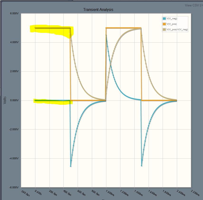
So I played around with that circuit for a little more than an hour and here are some observations I made:
Now, after tinkering with these simulations, I tried thinking of some applications that would use these properties:
Honestly, I still would not intuitively know when to use a cap if I was designing a circuit. P.S. CircuitLab is really cool, though there are some bugs I'm hoping you can squash. Keep up the awesome ideas rolling in! |
|
March 01, 2012 by hevans (NerdKits Staff)
|
Hi Drwish, I think all the observations you made were dead on. You meantioned the cap not discharging until the second duty cycle. I'm not really sure what you mean by this. Perhaps you are getting confused by the initial conditions of the capacitor. In the simulator the initial conditions of the capacitor are set by running an DC operating point solution first, so in this particular circuit the capacitor will start out with 5V across it, and when V_pos goes down to 0, it will drag V_neg down to 0 then begin discharging through the resistor. The frequencies which a high pass filter dampen is related to the size of the capacitor and the resistor. I'm sure the electronics book you are reading is going to get to this at some point. Your last bullet point is the real takeaway from this sort of circuit. The aim was to remove the DC bias. You also mentioned that it dampened the sine wave, which in this case can be a bad side effect. If you dampen it too much you end up squashing the signal you were trying to get out in the first place. These are the kinds of trade offs you have to consider when designing circuits. Intuition is something that you build over time by working with circuits. Hopefully you at least get what the capacitor is doing in this particular situation. Please let us know what bugs are talking about on the CircuitLab forums. Humberto |
|
March 01, 2012 by Drwish
|
That is what i see when running a transient analysis after running the DC solver. V_Neg is 0 during the first duty cycle. Also, when a sin wave is recentered around 0, what happens to the components that rely on this output signal when the voltage is negative? |
|
March 01, 2012 by hevans (NerdKits Staff)
|
V_Neg is 0 when the circuit first starts up because the simulator starts every node voltage at its DC operating point solution. This is just so it can properly define the node voltages for the time domain simulation. Audio waves in most electrical circuits are assumed to be centered around 0, so whatever device the mic gets plugged into should expect that and deal with that properly. If you were to plug this directly into your headphones (for example) the speaker diaphragm would move in one direction when the voltage is positive, and in the opposite direction when the voltage is negative, which is exactly what you want. Humberto |
Please log in to post a reply.
|
Did you know that a square wave sounds different than a sine wave? Learn more...
|


Copyright © 2013 by NerdKits, L.L.C.