NEW: Learning electronics? Ask your questions on the new Electronics Questions & Answers site hosted by CircuitLab.
Project Help and Ideas » 4x40 LCD
|
January 08, 2012 by Rick_S 
|
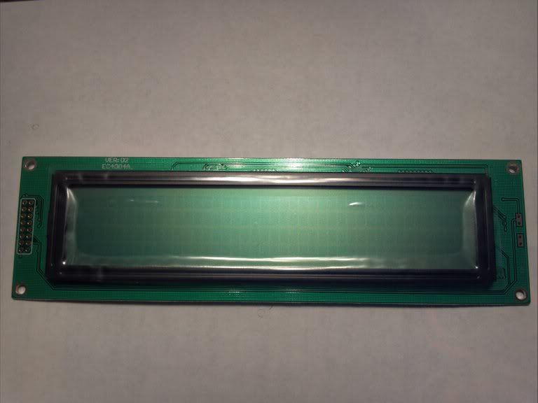
Did you ever need more room on your LCD display than the 4x20 provided with the NerdKit? Well I'll admit, I didn't really NEED more room, I just thought the idea would be nice. So when I came across a 4x40 LCD for under $3.00 US, I couldn't pass it up. The other good part of this display is that it's chipset is compatable with the HD44780 in the NerdKit LCD.
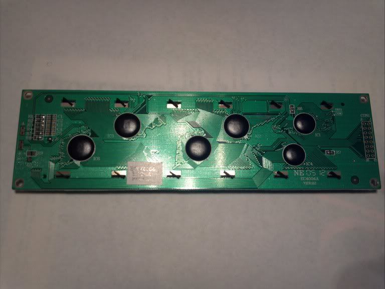
Once I got my display, I had to solder in a 16 pin (2x8) Header connector so I could wire it up. That done, I simply made up a cable and was ready to start testing it out. Here is a breakdown of the pinout of this LCD Vs the Standard NerdKit LCD.
As you can see, the pin callouts are very similar, there are a couple of differences though.
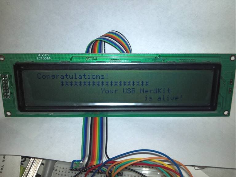
1st Question, Why 2 enable lines? Because this display has two full chipsets to control all the screen positions. According to the datasheet for the HD44780, it has character ram for 80 characters. On the NK LCD, this is 4X20=80. This display however has 160 available characters so it needs 2 chipsets. To control them independantly, there is an enable for each chipset to designate whether you are writing to the upper half of the display or the lower half. To make the display work, I made a new library completely based on the NK original lcd.c library. I called the new library lcd_4x40.c Here is a photo of the LCD displaying our familiar initial load. (The offset is on purpose
To use this library, you will have to make a couple of changes. 1st you will have to change your makefile so it creates an object file for the library and includes it at compile time. Here is the makefile I used: Here is the library: For the .h file, simply copy the original NerdKit lcd.h file into a new file called lcd_4x40.h as no changes were necessary from the original. Here is a modified initialload.c that I used to test the display and some positioning. If you are interested in the display, I found them at a company called Prime Electronics Here is a link to them Happy Programming Rick |
|---|---|
|
January 08, 2012 by Rick_S
|
One other note, if you do get one of these displays, let me know if you find any bugs. Rick |
|
January 09, 2012 by Rick_S
|
I forgot one detail, be careful when wiring the connector. If you do install a header connector like I did (from the back side) the pin order is opposite what would be standard. On a standard header the pins would be numbered like this: Since this is wired from the back side they are reversed like this: If you are used to standard header layouts, it's easy to get your mind turned around. Rick |
|
January 15, 2012 by Rick_S
|
I was just thinking as I was looking at the display on my desk. If anyone is interested, I could take the post from above and put it in the library so it doesn't get lost in the forum. If no-one responds, I'll take it that no-one is interested and leave it alone. Rick |
|
January 15, 2012 by Ralphxyz 
|
Yeah Rick, I got four of the 4x40 LCD after you made your post. Please put this in the Nerdkits Community Library I do not know when I will ever get around to having the time to set them up but I sure like the 4x40 concept. Ralph |
|
January 15, 2012 by Rick_S
|
Library article added HERE. Rick |
|
April 24, 2012 by Ralphxyz
|
Hey Rick, what will I have to do to use your I2C LCD backpack? I was thinking maybe I could use one of the unused pins for E2. But that is just off the top of my head without looking into it yet. I should have my 4x40 LCD running today. Ralph |
|
April 24, 2012 by Rick_S
|
Electrically, you could probably tie into one of the unused outputs on the expander for E2. The library would also need modified to support the display similarly to how I did the standard library. Rick |
|
April 24, 2012 by Ralphxyz
|
Now in looking at your library I am really getting dangerous and wondering why there is a E1 and E2. Well I understand why there are two enables as you explain but they are doing the same functions in the code. There are a couple of places you turn E2 off but I haven't figured the exact reason why. So I am "thinking" about just using the E1 pin and splitting it to pin 9 and 15 on the 4x40 header. They would both be enabled at the same time what is the problem with that? Besides it is not conventional. Ralph |
|
April 24, 2012 by Rick_S
|
If you re-read my first post in this thread, you'll see why there are two enable lines. The display is essentially two displays in one with the top two lines controlled by one controller and the bottom two lines controlled by another. The data lines for the two controllers are tied together and they are individually controlled by the separate enable lines. If you tie the enable lines together, the top two lines and the bottom two lines will display the same data. Rick |
|
April 25, 2012 by Ralphxyz
|
That would be "if you re-re-re-re-read my first post in this thread". It will all eventually sink in, oh well back to the unused pin idea which is to bad because then I'd actually have to do some programming. Ralph |
|
April 25, 2012 by Rick_S
|
:D I have to re-re-re-re-read things often myself... takes a few times to fully sink in sometimes. If you usea an unused output on the expander, you'll have plenty of programming to do :) Rick |
|
April 25, 2012 by Ralphxyz
|
Yeah, and I am not a programmer but I play one on TV. Ralph |
|
April 25, 2012 by Ralphxyz
|
Ok I am "trying" to do it your way. I have everything explicitly wired as you directed but my LCD does not light up. No blackbars no nothing. I compiled your initialload program and made a .hex so I guess it compiled but the make output was different than I expected. Of course your Makefile syntax is different than the standard Nerdkit Makefile so I am not surprised the make output is different. So why wouldn't the LCD light up? Ralph |
|
April 25, 2012 by Rick_S
|
Ralph, I just e-mailed you my hex that worked on my display... Rick |
|
April 25, 2012 by Ralphxyz
|
Thanks, still trying to figure out why the LCD does not work. I would assume there ought to be black bars. There is no backlight I can not use that as a working indicator. Speaking of backlight the are A and K connection points. Ralph |
|
April 25, 2012 by Rick_S
|
Sorry Ralph, I don't understand what you are asking. If you are asking about the A & K on the back of the display board, I think the board was designed to have a backlight but the version we have does not have one. Maybe double check your wiring, remember, header connectors like that have the odds on one side and evens on the other, they aren't like ic's they go: Also the pattern may be reversed depending on which side of the board you are on. Rick |
|
April 25, 2012 by Ralphxyz
|
I am asking why the LCD is blank, no black bars in programing mode. The backlight A K is just a curiosity. Ralph |
|
April 25, 2012 by Rick_S
|
I haven't connected mine in a while so I can't validate, but I believe if everything is connected correctly and if the right contrast resistor is used, it should behave just like the NK display. If you ignore the 2nd enable and just wire it like the NK display, the 1st two lines should work with thier(NK Guys) library except lines 2 & 4 will be at the end of lines 1 & 2. I'm sure you've re-checked the wiring, next maybe you verify the power and contrast to make sure it's good. If I have time tomorrow I'll dig out my display and connect it and get you some close up photo's. How did you connect to the display? Did you modify a ribbon cable or solder directly into the display board? Do you have a photo? Rick |
|
April 25, 2012 by Ralphxyz
|
I soldered on a header and have jumper wires. My voltage regulator is really heating up and I only see 2+ volts across the rails so it acts like there is a short. I only have VDD (pin 13) and GND (pins 14 + 16) no other wiring. Ralph |
|
April 25, 2012 by Rick_S
|
Weird... does sound like a short somewhere. Maybe time to get the magnifier out and check for solder bridges. Hopefully you didn't get a bum display. |
|
April 26, 2012 by Rick_S
|
Ralph, I did plug in my display this morning (power and ground in appropriate places and the contrast resistor installed) and confirmed it does display the two black bars, |
|
May 03, 2012 by Ralphxyz
|
Rick, where did you get the pinout from? AVRfreaks and most of the Arduino code I have seen They list 4x40 Pin 13 as GND and Pin 14 as Vdd You show just the opposite. I just got back to playing with this. Ralph |
|
May 03, 2012 by Ralphxyz
|
Yup, that did it!! It's working with 4x40 Pin 14 Vdd(+) Pin 13 Gnd(-). Now to test your library!! Ralph |
|
May 03, 2012 by Ralphxyz
|
Your initialload.c program works great!! I could not load your .hex and could not load the .hex I compiled so I just used the Makefile from the Nerdkit's initialload program and the program compiled and loaded fine. Now to get my Graphic LCD working and then I like to do a touch screen but I probable will need a different mcu than the 328 or 168. Thanks, I really appreciate your great projects. Ralph |
|
May 03, 2012 by Rick_S
|
Good catch Ralph, Sorry for that. I'll fix that on my blog right away. If you have any problems with the display because of this let me know... |
|
May 03, 2012 by Rick_S
|
I've updated the library post here with the proper pinout chart. Thanks again Ralph. I'm also deleting the image that is incorrect so the pinout chart above in this thread will be missing. |
|
May 10, 2012 by Ralphxyz
|
Now this is strange, I tried modifying your 4x40 initialload but only lines 1 and 2 displays text!
So I went back to your original code and still only got lines 1 and 2. Then I noticed the MakeFile was for an atmega328p but the initialload.c program is for a ATmega168, there is no which isn't strictly required for 328 code to run as long as you do not make any calls for io_328p.h components. Any way I set everything up for a 168 and only get two rows of faint black boxes with the box in position 1, on line 1 and 3, blinking. For the 328 I get text in line 1 and two with black boxes on line three, not sure if the position one box is blinking, I do not believe it is. So once agin something strange is happening that I can not restore the original program. I hate all of the wires so I made up the ribbon cable. I forgot how easy it is to break the IDC (insulation displacement connector) if you do not have the proper tools so I ordered IDC compression tool off ebay and still managed to break a couple of connectors before figured out how to use it (two steps don't use compressor for final piece). I "believe" the wiring is correct as it did work once. Ralph |
|
May 10, 2012 by Rick_S
|
Check the 2nd enable line. If it isn't connected properly, the lower half won't initialize. You are using the 4x40 library right?? As for the io_328p.h stuff, I added those definitions to the main libraries a long time ago, so I don't always think of using that include. Rick |
|
May 10, 2012 by Ralphxyz
|
Now this is interesting. I connected my scope to E1 and definitely can see when E1 is enabled but when looking at E2 I do not see the enable! Wish I knew how to take a picture with my scope also it would be nice to get the PC interface working. Ralph |
|
May 10, 2012 by Ralphxyz
|
Darn now the enable on E2 is showing up on my scope so the E2 enable is firing. I switched LCD's to make sure I didn't have a bad LCD, both show the same result. Well now line three is flickering and showing: fffffffffffffffffffffffffffffffffffffffffffffffffffffffffffffff 33333333333333333333333333333333333333 box box box box box box box box box box box box and line four will occasionally have characters. |
|
May 11, 2012 by Rick_S
|
I don't know what is causing that, maybe an intermittant connection?? You're trying to just run with the unmodified library right? |
|
May 11, 2012 by Ralphxyz
|
"unmodified library"?? This is with your lcd_4x40.c library from above with the renamed NerdKit lcd.h. Ralph |
|
May 11, 2012 by Rick_S
|
That's all I was using. I don't know why it isn't working there?? This may be another of your mysteries. Seriously though, maybe there is an intermittant connection somewhere. Have you tried it without the ZIF socket just plugging the micro into your board? I know you are a big proponent of the disassemble/re-assemble so I'm sure you've tried that. I'm at a loss and just grasping at straws. Sorry I can't help more, I'd really like to see it going again. Rick |
|
May 11, 2012 by Ralphxyz
|
Darn, I got it working using your initialload.hex that you sent me!! I loaded it using AVRStudio on my Windows 7 machine and it runs correctly!! Now I'll need to figure out how to use your MakeFile on my Mac or figure out how to use my MakeFile, geesch my beard hair has really turned white since I started learning microprocessor programming. Ralph |
|
May 12, 2012 by Rick_S
|
Ralph, Reading another thread made me think. Did you change the compiler optimizations in the make file? The Macs have been having issues unless you change the -Os to -O0 (Dash Letter O number Zero) to turn off optimizations. If you haven't done that, give it a shot. That might fix the erratic behavior. Rick |
|
May 12, 2012 by Ralphxyz
|
Ok, I have not done any programming for the past 6 months so I m not thinking as a programmer. My problem was I am not including your lcd_4x40.c Library!! You say:
Which I did, but how is your Library included? I cannot call it lcd_4x40.h if the Nerdkit lcd.h file wants to be included as lcd_4x40.h. Of course I could give it any name but I was not thinking as a programmer so that fact escaped me :-) I have never had a problem with the compiler optimizations. Ralph |
|
May 13, 2012 by Rick_S
|
lcd_4x40.c is compiled into an object file and linked in the makefile. That is how the same header file can call functions in a different 'c' file. As for the optimizations, it was just a thought seeing how many people seem to have issue with them. I haven't really done any programming on my mac mini... Actually haven't even turned it on in a couple of months Rick |
|
May 13, 2012 by Ralphxyz
|
Strange the compiler didn't complain about not finding lcd_4x40.o. Of course I wasn't thinking as a progrmmer (I have been doing my brick path for the past six months) so I need to be reminded to actually compile lcd_4x40.c into an object file. So once agin thank you for your great projects and exceptional help. Ralph |
|
May 13, 2012 by Rick_S
|
It probably wouldn't complain because with the standard NK makefile, lcd.c is linked and it has the same function names. So the program was satisfied. Using lcd.c though would give you only the top two lines being functional. The first half of line 1 being line 1, the second half being line 3. The first half of line 2 would be line 2 and the second half line 4. That would explain the "gibberish" you were seeing. How's the brick path coming? |
|
May 13, 2012 by Ralphxyz
|
Yeah, that probable explains it, ha. Oh well I consider myself to be a second year student in a electronics/microprocessor class so it is not surprising. The brick path is reaaally unbelievable. People say it has a lot of character, it certainly isn't your typical brick path installed by a professional that knoew what they were doing. But I love it and being outdoors at lest 4 hours a day is so good for me. I spent the last 20 years sitting at my desk for 12 to 2o hours a day and sometimes more acting like I was a network administrator/webmaster. I haven't updated the website lately I have laid most of the brick path and have one lamp post working plus I have been doing a lot of restoring the landscaping that got torn up in the excvation work. And for those of you wondering wht the heck a brick path has to do with Nerdkits, well I do need a light controller for the path lights that will be controlled by a Nerdkit mcu :-). Ralph |
|
May 13, 2012 by Rick_S
|
You have some beautiful property there Ralph. Someday I'd like to move to a coastal area and get out of the middle here where I am. I'm figuring further south than you are. I'm hopeful that if all goes as planned, by the time I get around to retirement age, I'll have my home paid off and be able to sell and buy outright with little to no mortgage for my silver years. That's the goal anyway. |
|
May 14, 2012 by Ralphxyz
|
Rick I am trying to compile your lcd_4x40.c, yes I changed the name. The pin defines are not being found. I am using Programmers NotePad in Window 7 (as long as it doesn't crash, geesch Windows 7 is worse that XP for getting "BSD" (Blue Screen ofDeath). I have not used Windows 7 for development enviroment for a long time so I do not know if there is something I hven't done after the last Windows 7 rebuild. Ralph |
|
May 14, 2012 by Rick_S
|
I modified my pin definition files in the avr-gcc install to include the missing definitions. If you haven't done that, you'll need to include the io_328p.h you mentioned earlier. That should fix the undefined pin callouts. Rick |
|
May 15, 2012 by Ralphxyz
|
Rick said:
(That's a quote in case you haven't read the stupid Markdown manual) And why would I want to do that?? Just to not have to: Ralph |
|
May 15, 2012 by Ralphxyz
|
Darn making the object file is not that straight forward. I've done it in the past just using a Nerdkit MakeFile but I think I need your MakeFile or your lcd_4x40.o file. Here are my latest errors: etc. etc. Of course I do not believe I have ever seen a step by step instruction on making a .o file so I am winging it and you know the trouble that means. Ralph |
|
May 15, 2012 by Rick_S
|
Did you get these errors with my makefile? I had the program file with the makfile in their own folder. lcd_4x40.c and lcd_4x40.h in libnerdkits. The line in the makefile that creates the object file is: You should be able to type that in the command line(substituting the value for GCCFLAGS) to manually creat the .o file. |
|
May 15, 2012 by Ralphxyz
|
All right I'll try with your MakeFile that would make sense. Ralph |
|
May 15, 2012 by Ralphxyz
|
See I can do it, I have the lcd_4x40.o and a new lcd_4x40.hex using your MakeFile!! Now to get into trouble making changes to your initialload.c. I have a muti-sensor ground temperature project in mind that I'll use the 4x40 LCD for. At $3.00 apiece I will not mind dedicating a LCD to a project. Thanks again for your projects and your faithful help. Ralph |
|
May 15, 2012 by Rick_S
|
No problem Ralph, glad it all worked out. My latest thing is playing with tube guitar amps. Kinda fun playing with 500 - 600VAC transformers. :D Rick |
|
May 16, 2012 by Ralphxyz
|
Is that where you always keep your other hand in your pocket? Now, are you learning to play the guitar and learning how to build a tube amplifier at the same time? I am able to change your initialload.c program and compile the changes, this is great. Ralph |
|
May 16, 2012 by Rick_S
|
Haven't started formal lessons yet, but am having fun building amps. I finished my 1st amp head using an old fender schematic with different tubes. As for the hand in the pocket, I don't do that but I do have a very real respect for the high voltage. Glad to hear the compiling is going smoothly now. Rick |
|
May 16, 2012 by Ralphxyz
|
I had a electrician (the crew boss) get across a couple of hundred volt 3 phase, he sure wished he had kept his other hand in his pocket. That's the first thing I was taught working on high voltage, of course that was power busses that I was learning on. Ralph |
|
May 17, 2012 by Rick_S
|
Yeah, at work with the 440V 3 Phase electrical cabinets for the machines, I always keep one hand behind my back. It's important also to overcome the natural tendancy to touch what you are pointing at when discussing something in the cabinet as well. Don't worry though, I plan to be around for a while to keep pestering you guys Rick |
|
July 21, 2012 by killercow |
Hi Rick, Thanks for fixing up the library to handle the 40x4 display. I purchased a couple of these 40x4 and the 40x2's. The 40x2's connect like the LCD that came with the kit. The 40x4's, on the other hand, needed to be toned out while looking at your chart and the KS0066 PDF file. I also had issues with E2 not firing correctly...odd. I ended up swapping E1 & E2 at the LCD and the bottom half worked. Then I swapped them back and I was in business. Pins 1 thru 6 are compatible with the NerdKit, E2 causes the data lines to be shifted over one to make them odd for wiring. But, who cares....I got 40x4 now...WooHoo!!! Thanks again to you and the rest of the gang. Kevin |
|
July 21, 2012 by Rick_S
|
No problem, glad it worked out for you. It's good to know it works with a different diplay. Does that display have a backlight? |
|
July 22, 2012 by killercow |
The 40x4 doesn't have a back light, the 40x2 does though. |
|
July 22, 2012 by Rick_S
|
The 40x4 I got didn't have backlight either. I was just curious whether the one you got did since it didn't say in the listing. |
Please log in to post a reply.
|
Did you know that 20 LEDs can be controlled from 11 microcontroller pins, to make a twinkling heart outline? Learn more...
|


Copyright © 2013 by NerdKits, L.L.C.


 so I don't know if the optimizations would effect me or not.