NEW: Learning electronics? Ask your questions on the new Electronics Questions & Answers site hosted by CircuitLab.
Support Forum » Trying to use SPI interface with Maxim 6675 - can't get SCK to output on PORTB2
|
July 22, 2009 by smilingjack |
I'm trying to set up the native SPI function on the Atmega168 so I can monitor one of the new Maxim 6675 thermocouple read chips. I've checked my DDRB and it is 0b00101100 so SS, MOSI, and SCK are set to output like the data sheet says. I've also checked my SPCR and it is 0b01011111 so SPI is enabled and Master is set along with cpol, cpha, spr1 and spr0. I set spr1 and spr0 to 1 (freq/128) so I should be able to see the shift clock on my ole 60 mHz scope. I've also tried all combinations of cpol and cpha but no luck When I set the SS low, wait a little and then load a char into the SPDR the SCK should send out 8 pulses but it doesn't - and I know it doesn't 'cause I'm watching on a 'scope. Anyway here's the code. I'm pretty new at C. I'm hoping a fresh pair of eyss might save my older one's |
|---|---|
|
July 23, 2009 by smilingjack |
Update: The reason I couldn't see the SCK pulses was that one o'scope channel was connected to ground but .... Then I finally solved the real problem. What is not mentioned in the Maxim 6675 documentation is that the chip takes almost 200 milli-sec to finish a conversion -- so one must wait at least this time - after raising SS - before lowering it, otherwise one will get get a reading but it is garbage. On a side note for other noobe's, I also found what clears the SPIF bit in the SPSR register after a byte transfer. It takes two actions. One is accessing the SPSR and, the other, is loading a new byte into the SPDR. Until I found this, I couldn't figure out why the !(SPSR & (1<<SPIF)) could signal the end of consecutive bytes of data transfer. It pays to read the documentation. |
|
October 27, 2009 by Keith726 |
smilingjack, I'm a newb also. One question: I see that the Maxim 6675 chip is packaged as surface-mount SOIC, not the DIP through-hole pins that we use with the Nerdkit. How do you connect SOIC chips to your board? Is there an adapter that I can get? Please tell me the secret. I would love to use that chip, and may others that are only available as surface-mount, but I don't know how. Keith726 |
|
October 27, 2009 by mrobbins (NerdKits Staff) 
|
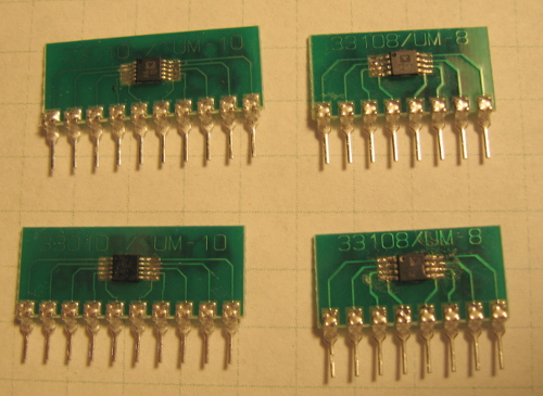
Hi Keith726, I'm not sure what smilingjack is using, but in the past I've used little adapter boards like this one from the Surfboards line. You can see the entire product line for various sizes of surface mount ICs. Be very sure to check the dimensions against the chip datasheet before you buy! Particularly the spacing between two adjacent pins, and the spacing between the two rows of pins. Mike |
|
October 28, 2009 by Keith726 |
Excellent! - thank you Mike. Keith726 |
|
October 28, 2009 by mrobbins (NerdKits Staff)
|
I should also mention that if you haven't soldered little surface mount stuff before (or even if you have), buy several extras of both the IC and the adapter boards. You may need them! I remember once soldering some little 8-pin and 10-pin ADCs and DACs, and I needed to get 2 of each working. I think it took ~4 of each, and ~4 of each board to end up with 2 working ones. Especially if you haven't done it before, it's really easy to bridge adjacent pins, or overheat the boards and make the copper peel off, etc.
Mike |
|
October 31, 2009 by Keith726 |
Thank you Mike - you guys are the best! This will solve many problems for me (plus, as you've described, create a few new ones, but what the heck!) Keith726 |
Please log in to post a reply.
|
Did you know that multiple MOSFETs can be used in parallel to switch bigger currents on and off? Learn more...
|


Copyright © 2013 by NerdKits, L.L.C.