NEW: Learning electronics? Ask your questions on the new Electronics Questions & Answers site hosted by CircuitLab.
Basic Electronics » Using Usbasp for attiny25
|
April 08, 2011 by dgikuljot |
Hey Guys, I recently bought an Usbasp programmer of of ebay and a blank attiny25 chip. I have everythign hooked up but am not sure how to program the chip. I have messed around alot with it and avr studio. So how do i make the .hex file to burn into the chip. I already have the code written. Thanks, Kuljot Dhami |
|---|---|
|
April 09, 2011 by Rick_S 
|
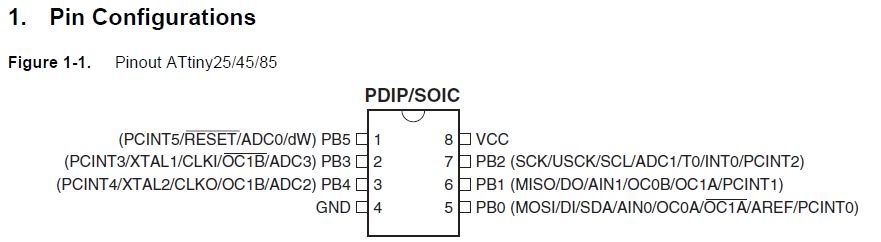
Hello, I have programmed attiny45's and attiny85's with a programmer with the USBASP firmware. Those devices are pretty much the same other than the amount of available memory. Which USBASP device do you have? Essentially, this is how to do it. 1st I'll assume you either have the PDIP or SOIC version like this:
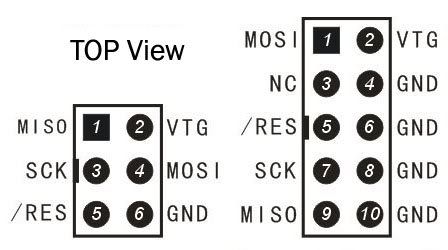
And that your USBASP programmer has either a 10 pin, 6 pin, or both interfaces:
NOTE THIS ILLUSTRATION IS OF THE JACKS ON THE BOARD From there, it's just a matter of connecting (FROM THE 10 PIN CONNECTOR): By default, the tiny25 will run at 1Mhz internal clock. Some Programmers have a low speed jumper (on mine it is J3). I have to use that jumper with the 1Mhz default tiny25 clock. After that, you can use some of the dircetions I put in the how to install a bootloader thread. In that thread I show you what to change in the makefile to use your USBASP programmer. HERE is a LINK to that thread. Do not attempt to install a bootloader though :)Rick |
|
April 09, 2011 by Ralphxyz 
|
Real quickly with out looking! If you are connected to the chip using AVRstudio then click on the program button in AVRstudio. Then enter the path to your .hex file and then click program. Ralph |
|
April 09, 2011 by Rick_S
|
Does AVR Studio even support the USBASP programmer Ralph?? |
|
April 09, 2011 by Ralphxyz
|
It must as he says " I have messed around alot with it and avr studio." so I assume that means it connects. Thats what prompted my reply. I'll fire up my windows computer and take a look. Ralph |
|
April 09, 2011 by Ralphxyz
|
I just looked in AVRstudio. The USBasp programmer is not specifically listed, which is not surprising. The AVRISP and AVRISP mkII is listed. Is the USBasp an emulator of the AVRISP programmer? Of course the STK500 is listed. So I do not know how dgikuljot was able to have messed around alot with it and avr studio except that it used some sort of clone. It certainly will be interesting to find out, if AVRstudio can talk with a USBasp programmer that would open new doors. I do not have a USBasp programmer so I cannot test. So dgikuljot how were you able to mess around in AVstudio? Ralph |
|
April 09, 2011 by Rick_S
|
I don't believe the default USBASP firmware will work directly with AVRStudio. It enumerates as it's own USB device and not a serial programmer. That was why I was referring him to the avrdude mods I made to the makefile in the bootloader thread I posted. Since I have a USBASP programmer my makefile mods would work out of the box with avrdude. There may be alternate firmware that is hardware compatable with his programmer, but unless he has another ISP programmer to re-program the firmware on his USBASP, that wouldn't help much. :) dgikuljot one thing I forgot to mention, when progrmming the chip, make sure you put a resistor (I usually use 10K) between the reset pin of the chip and VCC. This will ensure the reset works properly when programming. Also, if you want to program this chip as you would one of the nerdkit chips, you can edit the NK makefile for your programmer, and chip type and it will work. You don't have to use AVRStudio unless you want to. Rick |
|
April 09, 2011 by Ralphxyz
|
There is a thread on AVRfreaks.net about using USBasp with AVRstudio. If you Google USBasp and AVRstudio there are a number of returns so I guess it is possible to use AVRstudio. I believe different open source drivers are used. I'd like to know what dgikuljot was using. Ralph |
|
April 09, 2011 by dgikuljot |
First of all I would like go thank everyonw for the replies. When I said messed around with ave studio I meant I tried to make a hex file but Iwant succesful. I will check outsome of these links and reply later |
|
April 10, 2011 by Rick_S
|
Ralph, I did google it. The results I found appeared to state you needed a new firmware... Thus changing it from a USBASP to enumerate as a different programmer. avrdoper was on such firmware. But unless he has another way to burn the firmware on to his usbasp chip, that would do him no good. Also, USBASP is an opensource firmware project with a basic schematic given. Their are dozens of variations to the hardware that may or may not be compatable with firmware other than the USBASP firmware. That was why I asked what type of programmer he purchased. Mine for instance can have an AVRISP MK-II compatable firmware installed that would work directly with AVRStudio. Kuljot, To develop for the AVR, you don't have to use AVRStudio. If you don't mind my asking, what level have you gotten to in your programming abilities? Have you gone through the entire guide with your Nerdkit? While the Nerdkit uses a different method of sending the program to the chip than an attiny25 would, the program creation is very similar and the code is virtually identical. For instance, if you wanted to send the led_blink program to the attiny25. You'd 1st have to modify the source code to use possibly PB1 instead of PC4 since the attiny25 has no PORTC. Once that is done, you would also need to change the clock freqency. So the define for F_CPU would be 1000000 instead of 14745600 for a stock chip. Then you'd have to change the makefile so it would compile the code for the proper chip and use your USBASP programmer like this. After you've done that, you should be able to blink an LED placed in series with a 1k resistor connected between pin6 and ground. Also, the internal clock can be bumped up to 8MHz by changing the fuses in the attiny25 if need be. However, the chip will run lower power at teh 1MHz default clock. Rick |
|
April 10, 2011 by carlhako |
I found this site really helpful (http://www.engbedded.com/fusecalc/) to get my fuse settings when programming an attiny. I found out of the box they were set to use the internal crystal and had a prescaler of /8 set so it was running at 1mhz. |
|
April 21, 2011 by dgikuljot |
Hey Guys, SOrry i havent responded in such a long time. We had exams at school and i was really busy. Basically i hooked up my mcu to the usb and checked the connections 5 times. I used Ricks method to modify the makefile. The compiler attempts to program the chip but then i get this error I have checked the connections atleast 5 times and rewired everything over multiple times and everything is connected correctly. I read online that in some cases the programmer needs to be slowed downd to accomodate for the 1mhz internal clock of the mcu. Unfortunately my programmer has no jumper to slow down the programmer. Here is the link to the programmer i bought http://cgi.ebay.com/ws/eBayISAPI.dll?ViewItem&item=320682999661 So does anyone have an solutions.
P.S. I am not using an external Power supply, supposively the programmer is capaable of supplying boltage to the mcu.
Thanks,
Kuljot |
|
April 22, 2011 by Rick_S
|
Kuljot, One thing I didn't mention directly (it is mentioned in my bootloader thread) is that you must have a pullup resistor on the reset pin of the microcontroller (Pin1) I typically use a 10k resistor between that pin and VCC (5V) If you don't have this, the programmer will not be able to reliably toggle the reset line as needed to program the chip. If that doesn't work, then you would need to see if you could trace out the microcontroller on your programmer. The high/low speed jumper for a usbasp device should connect PC2 to Ground for low speed and be open for high speed. I'd download a copy of the datasheet for the micro-controller they have on their board then trace it out from that pin. I noticed a set of empty solder pads labeled R8 next to the micro on the programmer, these may be for setting low speed of course you'd have to verify this with the circuit trace. Hopefully you'll get lucky and the pullup will fix it. Rick |
|
April 22, 2011 by Noter 
|
Hi Rick, Where can I find technical info on these inexpensive programmers. Do you know if they all use the same firmware? Is it freely available somewhere? |
|
April 22, 2011 by dgikuljot |
Hey Rick, Thanks for all your help so far. The pull up resistor did nothing, and the mcu is an atmega 8 surface mout. So once i find the pin should i connect it directly to ground or with a resistor. Yeah i noticed the empty R8 too. So could there be anything else thats going on. |
|
April 22, 2011 by Rick_S
|
Noter: The USBASP is a real easy to build (I breadboarded one once) programmer. It uses very few external components and works great with avrdude. They have a full schematic and source code on their site. Kuljot: Once you find the pin for PC2, you may find it traces to the pads for R8 and the other side of R8 may trace to ground. Then again, it may not be connected at all. Either way, to set the programmer to low speed programming using the default USBASP firmware, you would tie PC2 to ground. Again, I'm just guessing at R8 since I don't have one of your programmers. I purchased mine from fun4diy.com. Out of the box his programmer has an AVRISP MkII firmware that is somewhat flakey with win7 supposedly I opted for the USBASP firmware. It has performed very well for me and I've programmed tiny 45's, tiny 85's, mega8's tiny2313's, and many others with it. I'm sure once you get your's figured out it will perform well also. Rick |
|
April 22, 2011 by dgikuljot |
Hey Rick, Apparently after doing some reading online i have learned that if there isnt a jumper 3 to slow down the programmer, that most likely the usbasp has been decided to automatically adjust to the targets speed. |
|
April 22, 2011 by Rick_S
|
I had heard of the newer firmware doing this, I'm not 100% how well it works though. I know the last tiny45 I programmed about 2 months ago, I had to add the jumper to get it to talk to it. I guess it just depends on the firmware they programmed your device with and if it is the auto-sync firmware, how well the auto-sync works. Could you post some photo's of your setup for programming it? Close ups of the connection of the programmer and breadboard. Maybe we can see something... Rick |
|
April 22, 2011 by Rick_S
|
Ok, Read up a bit on the speed thing, If you have the latest firmware, the speed can be controlled by a switch in avrdude. Try adding the parameter -B 100 to the ARDUDEFLAGS line in the makefile like this: See if that makes it work... Rick |
|
April 22, 2011 by dgikuljot |
Hey Guys, The parameter didnt work either, so only thing left to do is solder a wire on to pc2 to ground. Man i really wish the atmega 8 wasnt surface mount. So do you guys know of any other probable causes for this error. If the grounding of pc2 doesnt work then i will post a picture of my setup |
|
April 22, 2011 by dgikuljot |
Connecting pc2 to ground produces the same results. The Resistor8 that is missing traces back to PB2, but you said to ground PC2. I dont know what to say at this point. |
|
April 22, 2011 by Rick_S
|
Photo would probably be best at this point. |
|
May 20, 2011 by dgikuljot |
Ok Sorry guys that i have been so late to reply to this. I basically replaced the usbasp with another one and this time it proceeds further. But now i am getting an error : adress 0x0810 out of range at line 129. The hex file is 22kb for some reason, i am assuming this is way to large for the attiny 25. So why is the hex file turning out so large. Here is my code: So from my research i know i am getting this error because the hex file is to large for the mcu and it is too large at 22kb, but why is such simple code turning out to be 22kb. THanks, Kuljot Dhami |
|
May 21, 2011 by Rick_S
|
I know there are compiler optimizations and such, but I haven't found a definitave answer to this. Like you, I would love to find the answer. However, I have not dug into it because, since I know I have issues with C, I just go to BASCOM AVR or assembly when building programs for anything less than the 168's. I have specifically run into this with mega8's, tiny45's, and tiny85's. If you have any knowledge of programming in BASIC, BASCOM AVR has no restrictions in it's demo for a chip that size. The only limitation in it's demo is a 4k code size restriction which is double that chip's capacity. Rick |
|
May 21, 2011 by Noter
|
The large size is due to the libraries you are linking with. For a small hex file, remove these libs from your gcc command: |
|
May 21, 2011 by Rick_S
|
Are you saying just remove that whole line (make the line read LINKFLAGS=) Rick |
|
May 21, 2011 by Noter
|
If that is all that is in the linkflags, then yes. Here is a gcc command from one of my projects that I use to build a small image. Also, don't rely on the size of the hex file for the size of your image. Open the .ass file and scroll to the bottom. The last address plus the bytes used in the last instruction is the actual size of your image. If for some reason you don't load starting at 0x0000 (like the bootloader) then you will have to substract your start address from the end address to get the image size. |
|
May 21, 2011 by Noter
|
By the way, "image" means executable program image. Not to be confused with a bitmap or jpg type image. Here's another example that I use to build my bootloader which is slightly less than 1kb in size. As in my previous post, there is no printf, scanf, or math lib specified for the link. |
|
May 21, 2011 by dgikuljot |
OMG Rick and Noter, Thank you so much. Just Leave the And everything works fine. Everything is working now and i can get back on track on making my Remote computer start system. Now i just need to find some useful libraries for avr and ill get back to work. |
|
May 21, 2011 by dgikuljot |
So Rick, I have one final question for you rewgarding this. I downlaoded the manual for bascom and it seems alot easier to program in Basic then C. So my question is will writing code in basic be just as efficient and fast as writing it in "C" for the MCU. Also does BAscom supprot Usbasp. Thanks, kuljot Dhami |
|
May 21, 2011 by Rick_S
|
Bascom compiles pretty compact efficient code. And yes, USBASP is supported within it's gui. I actually was programming micro's with bascom prior to purchasing my NerdKit. The main reason for getting the Nerdkit was to teach myself C. However, for simple projects - especially for smaller micro's, I will still occasionally use Bascom. Rick |
|
July 18, 2012 by lnino 
|
Hi at all. I am right now trying to flash a ATTiny45 with an existing HEX File. I want to share this informations, which maybe can help some people. How to: First you have to erase your chip: In my case I used an usbasp flasher. I want to flash an ATTiny45, because of that I have chosen t45. In these lists you can find the right name for your programmer and you chip.
After that I made the fuses: On THIS site you choose your chip and have a look which settings for low, high and extended have to be set. After that you can flash your HEX file to the chip: Remember you have to change to the directory where the HEX file is, when you enter the command in the command line. Now your program should be on your chip. The wiring has been solved by Ricks Tutorial above. Rick, thank you so much, for sharing this.
Hope I could help. |
|
July 18, 2012 by killercow |
Hi, Just reading thru the thread and I would be hesistant on setting the fuses prior to programming the chip. I've been playing around with using an ATTiny85 as a USBTiny programmer. This requires you to set the /RST line as an input line(?) via the fuse settings. Once the /RST line is changed, it can only be changed by using a HVPP device to reset it back to the original fuse settings. Well, last laptop is imaging for the day....heading home.... See ya! Kevin |
|
July 19, 2012 by lnino
|
Hi at all. I have following issue. Now I am able to do the following: + Write a program with the Nerdkit USBtoSerial Cable to the ATMEGA168 + I am able to write the bootloader with the usbasp to the ATMEGA168 + I can write a HEX file(downloaded from a website) to almost any Microcontroller as I described above with usbasp But I want to do following: + I want to write a simple program(f.i. flash_led.c) into f.i. ATTinyxx,ATmega8,ATxmega... with the hardware I have(nerdkit,usbasp) I really have no clue how to do that. With the ATMEGA168 and the USBtoSerial cable it's really easy. Would be great to have a same easy prodecure to to write my flash_led.c file to f.i. ATTiny, ATmega8,.... Hope to hear from you. Thanks for your help. |
|
July 19, 2012 by dgikuljot |
@ Inino This website has good tutorials for avr microcontrollers. He also uses an isp to program the chip which is similar to USBasp. http://newbiehack.com/MicrocontrollerTutorial.aspx |
|
July 21, 2012 by lnino
|
Hi, thanks for your reply. I will have a look at your link. |
Please log in to post a reply.
|
Did you know that our USB NerdKit works on Windows, Linux, and Mac OS X? Learn more...
|


Copyright © 2013 by NerdKits, L.L.C.